Monday, June 28, 2010

Cap Kart Summer Rebuild 1

The Cap Kart rebuild has begun in earnest, so I'll try to post semi-frequent updates on the progress. It's a summer-long project, hopefully culminating in some new test drive video and data by August. The static website will eventually be updated as well.

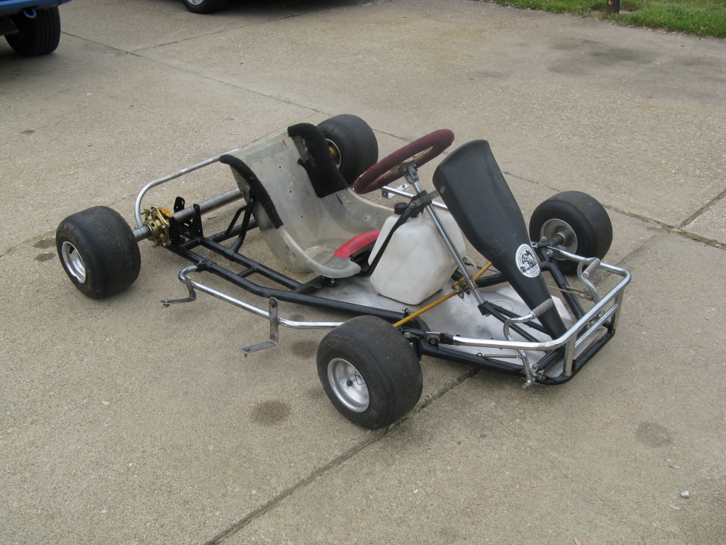
First, the kart diff. This is a real mechanical test for us. In 2008 we chose to invest in an engine-less racing kart specifically so that we would not have to mess with any critical chassis or drive mechanics, short of adding a chain and sprocket for the electric drive motor. Now we're essentially tearing apart the rear axle to add a custom-built axial differential. It's a lot of heavy-duty steel fabrication...

Serious Business.

 ...for a group that's used to designing aluminum parts to be cut on an abrasive waterjet and carefully assembled. But rest assured we can bring some of our skills to bear on the project. Namely, making it look good.

Photo-render courtesy of DiffMaster Max H.

Now might be a good time to explain how it works. Like a more conventional bevel gear differential, the axial differential allows a single input (the chain drive) to supply torque to both rear wheels, while still allowing them to rotate at different speeds. This is most obviously necessary when turning, since the outside wheels must travel faster than the inside wheels. An "open" differential like this follows a simple rule: the torque on each wheel must be the same.

Formula SAE cars often use a chain-drive differential (though probably not axial) on the rear axle. In fact I'm sitting right next to one so why don't I take a picture?

 See it?

It's inside that aluminum can.

It's not obvious from the picture, but the brake disk and sprocket are both fixed with respect to the differential case. This way, braking torque is applied at the input and split to the rear wheels in the same manner as accelerating torque. We'll be pursuing a similar design in ours, mounting the brake disk to the hub opposite the new sprocket.

It will be fun to assemble. For now, though, it's just lots and lots of fabrication:

 Gear stock is cut to length, then bored out.

Hubs are formed out of aluminum disks. 
 
Ready to add holes for the gear posts.

Nearly completed hub.

And the gears actually do mesh...so far.

 While the mechanical side is progressing, I've been trying to remember how exactly the controller works. (I mean, conceptually I remember what it does, but the details of the wiring have been lost a little bit to time.) While we're rebuilding and adding new lithium-ion batteries, the plan is to update the power electronics as well. The only substantive change, though, will be replacing the contactor/diode switching circuit that enabled the ultracapacitor boost and brake modes with semiconductor switches. Here's what I mean:

If you're looking at this schematic and thinking "WTF?" then you're in good company. It took us some time and some trial-and-error to settle on this particular method of using the Maxwell ultracapacitor module, and even longer to recognize that it actually does have some significant advantages over other methods. All that is part of Cap Kart v1 development history, though, so I won't focus on it here. If you stare at the circuit for long enough, it might make sense.

The only change is that where there was a contactor and diode before, there is now a second high-power half-bridge. This bridge will only be used to turn the capacitor boost on and off, but in theory it could also be PWMed to modulate how much capacitor assist to use. That's too fancy for us, though. The purpose of this upgrade is mainly to take out one extra diode drop from the circuit.

We'll also be exploring new control modes for the separately excited motor to squeeze every ounce of power out of the system. The new batteries, though much lighter, do have a relatively low peak power and one of the challenges will be to make the most out of it. In some sense, this will give us more of an opportunity to demonstrate the advantages of the ultracapacitor assist. (Before, the oversized AGM batteries could have sourced or sinked enough power to make the capacitor somewhat unnecessary.) 

More to come...

Saturday, June 26, 2010

HexBridge Shield BLDC and this silly thing from Texas Instruments

First, the Arduino HexBridge Shield BLDC challenge has been answered. In this post, Charles shows that it's a relatively simple matter to write control code for the Arduino that will turn the HexBridge into a viable brushless DC motor controller. As I mentioned (but was too lazy to prove) in the original post about the HexBridge concept, BLDC control involves setting one phase as high (or PWM), one as low, and one as off/floating. By cycling through all 3P3 = 6 permutations of this, you get rotational motion. The trick is linking this to the Hall effect sensors (or something else) that determine which state should be active. Here's the light load test video.

Dual BLDC control (when would you ever need that?) is simply replicating this on the second set of three half-bridges. Or you can run one BLDC controller and one reversible brushed DC controller using two out of the three remaining outputs. Or...well, you get the idea. Configuration flexibility proven, the next step is probably heavy load testing to see its limits. So far, I've tested to 20A. How about 50A?

Now for a bit of a rant...


This is the new Texas Instruments MSP-EXP430G2 LaunchPad. It's a $4.30 (clever) development board for the MSP430 value line devices. Does it look like a red Arduino? Can you imagine the developers' meeting? I can:
Hey guys, we're getting killed in the entry-level market by this Arduni thing. How are we going to get new engineers and embedded developers to use our product in the future?
How about we like...create something that looks like it, but with our cheapest chip. And we'll make it red. And we'll sell it at a loss, to get people hooked.
Now, I love the MSP430 microcontroller line. I use the MSP430F2274, specifically. It is significantly better in many ways than the ATmega328 used by the Arduino. But the chips they use on this board, the MSP430 value line, are actually somewhat lacking in features. For example, they have only one timer (vs. the ATmega328 with three). Timers are critical for the kind of stuff I do, like motor control, so that is a little disappointing. But I guess for the entry level, at $4.30, it's still a good way to get people engaged.

Except...do people use the Arduino because it's cheap? Or has a convenient form factor? Or is it because it's easy to program? I'm tempted to say it's the latter. And the MSP430 line, while being a pretty standard application of C programming, does not have the convenient (did I really just say that?) simplified programming language or the backing of a giant user group that Arduino now has. So I'm not sure. Maybe if they had come up with the idea of making an easy to use MSP430 dev board a few years ago, it would have caught on and been developed more.

Oh, wait.

How is that quarter not shorting out the 3V3 and GND pins?

That's right. Cam and I thought of putting an MSP430 chip on a dev board in 2007. (Seriously, look at the date on the board.) The thought process was essentially:
Hey check out this new Arduino thing. I wonder if we could make a better one.
How about using an MSP430F2274, and making it small enough to fit on a standard breadboard? And integrating an XBee header. And, heck, let's just make it USB and wirelessly programmable too.
We called it the 430stamp, or, informally, the wootstick (short for Wireless bOOTloading...sort of). It is arguably the most useful thing I have ever made. Seriously, I use it for everything. Doesn't it look familiar? It's the signal board for the 3ph Duo controller, where it executes simultaneous field-oriented control of two brushless motors. It's also the transmitter AND receiver for my RC car. There's one for programming the Cap Kart wirelessly. They were briefly used in 2.007. In other words, they work well enough that I rely on them. Very few things I've ever made have gotten to that status.

So, will I be buying any MSP430 LaunchPads? Probably not. So many people have told me about them now that I might just buy a few out of curiosity. But I already have a good, reasonably cheap (~$20) MSP430 solution. I wouldn't mind seeing more people use these as opposed to Arduino, just because they will have to learn how lower-level embedded programming works. (Not assembly...but low-level C. Fewer user-friendly libraries.) Overall, a $4.30 dev board from TI is a good thing, but I'm not necessarily impressed.

Wednesday, June 16, 2010

Revenge of the Cap Kart


The Cap Kart; the most ambitious and the most unique vehicle in the fleet of the Edgerton Center Summer Engineering Workshop, an ad-hoc group that for the last three years has taken on projects "that you can ride." We built it to reduce our dependence on foreign natural resources go fast. The kart can't rightfully be called our flagship; that distinction belongs to a different vehicle. But it's the fastest and most powerful by far, and after sitting on the bench (literally) for a year, it's going to exact its revenge.

The kart gets its name from its defining feature, a capacitor of 110F/16V (yes, F) that stores braking energy and puts it at the driver's fingertips in the form of a boost button, similar to the push-to-pass KERS setup. It's made by Maxwell Technologies specifically for automotive applications, and it looks like this:


The "Cap" part of the Cap Kart actually worked more-or-less on the first try. In fact, the kart as a whole worked well enough to get in a few test drives, plus some good flywheel test data. But it was still a rough prototype. It was also very impractical to test, for a number of reasons: It was too heavy, too wide, and stored in a building with no ramp access. Moving it involved taking off all the batteries, going sideways through a door, up an elevator, out another door, and down a flight of steps.

Now that we have some new space with double-doors, wide hallways, a freight elevator, and loading dock access, many of these problems have gone away. In fact, it is feasible to take the kart out without ever lifting it now, which also means the batteries could stay on. Then again, of all the things on the kart, the most obvious target for improvement are the batteries. We started with three 79Ah deep cycle marine batteries (lead acid), each weighing a whopping 53lbs. That's 159lbs worth of batteries...or roughly half the weight of the kart without driver. And one of the three original batteries has since died. So, we're ready to move on.

 
...but don't worry, the old batteries have found a new purpose.

We talked about lithium-ion batteries back in 2008 when we made the Cap Kart, but at the time there were two big reasons why we opted not to use them. One: They were (and still are) expensive. The price has come down a good deal, even in just two years, but they are a big investment. Two: We did not have the experience working with lithium batteries to justify the investment. Lead acid batteries can take more abuse. Now, though, we're more confident in our ability to handle a low-voltage lithium-ion pack, so we're going to take it on.

Our cells of choice: the Thundersky TS-LFP40AHA. These are the same brand that the Mythbusters used on their electric kart. The cells range from about $40-80 each, depending on the source. We opted to get a kit, which includes pressure banding, bus bars, balancers, and a 15A charger. This was from Elite Power Solutions. They come in a nice thick cardboard box, shipped regular-old UPS (not freight or hazmat).


Cute.

We never really had a range issue, so the minor hit in total battery capacity will not be a problem. However, the peak current output of this pack is probably a bit lower than what we've become accustomed to. I measured the internal resistance of these cells to be about 3.5mΩ, which agrees with The Internet. That puts the realistic current output capability at something like 120-200A (3-5C). Our motor/controller was quite happy (or unhappy) with 300A. It would be nice to match the two current ratings a bit better. (Though at low duty cycle it doesn't matter.) There may need to be some...buffering, of sorts. And there's always that capacitor thing, too. Getting the most bang for the buck has become one of our themes, and we're pretty good at it.

The very reasonable goal is to cut the battery weight by 2/3. In other words, all of the new batteries will weigh as much as one of the old ones. Since the batteries are half the weight of the kart, that decreases the kart weight by 1/3. The drivers weigh the same, though, so really it's more like 1/5. Decreasing mass by 20% leads to a 25% increase in acceleration (because math is funny like that), all else being equal. Hey now, wouldn't it be nice to have some better handling to go with that extra acceleration?


Here's the rear of the kart as-is. It's a live axle: the wheels and rear axle are one rigid body. This is great for traction...not so great for tight turning, especially on asphalt. One wheel has to slip, which can be made easier if it is lifted off the ground by a combination of weight distribution and chassis flex. But we added a ton of weight to the back and welded solid steel battery trays across the entire frame, so so much for that. Instead, we're going to add a differential. And hey, it gives us another chance to rip off Charles Guan.

The last target for improvement will be the control(ler). That is, both the physical and the software side. As much fun as it was to blow up TO-220 MOSFETs over and over and over, I think we're ready for something a little more serious. And to go with it, a new control algorithm that takes full advantage of the separately-excited DC motor in the field-weakening (again?) region. It should be able to more closely approximate the constant-torque, then constant-power curve for which electric motors are so well suited. 

Oh, and the best part is that I won't be writing the software this time! Nor will I be designing the differential. Nor will I be cleaning up the wiring. (Okay, maybe I will a little because I have OCD.) But yeah, my favorite project team is on it, so I get to mostly just chill. Oh and figure out where the heck we're gonna test this thing...

Saturday, June 12, 2010

Arduino HexBridge Shield v2.0

This is what I meant to do the first time.

Recap: I have lots of motor controllers. Some of them work, others do not. But they are almost all based on a combination of MSP430 microcontrollers and a totally isolated, totally modular gate drive solution. Recently I've been feeling the pressure to create a more...populist...solution, which basically means putting it on an Arduino shield. So that's what I did.

Even though v1.0 was a total failure, it gave me a chance to refine the design in ways other than making it not go crazy as soon as it was under any load. I had some extra time to sit around and think about exactly what I would want in an Arduino-based motor controller. Well, not what I would want, but what one would want...you know. ;) Here is the important functionality that I was targeting:

Six semi-independent MOSFET half-bridges. I say semi-independent because each set of three shares a single PWM output. So, at most it can control two motors. But these could be brushless (3-phase) or brushed motors (H-bridge). You can also put channels in parallel for higher current capacity. There should be a simple state selection for each bridge: PWM, low, or float:


This leaves a ton of flexibility, and only occupies one I/O pin per phase, plus the two PWM pins. The "float" state is important for BLDC control or for disabling a phase entirely. I talked about some of the possible configurations in the previous post. On to the new board:


The FETs are the same (IRFS3107 or IRFS3207 or any other D2PAK), but they are arranged differently this time. All the high-side FETs are on the top, and all the low side FETs are on the bottom. This let me move the entire power section out off the side of the board, away from the Arduino and the logic. To conserve horizontal space, I switched to 12-13mm vertical capacitors. They can face up , or down into what will likely be dead space next to the Arduino main board.

Speaking of dead space, I stuffed the DC/DC converter input and output capacitors in the gap between the arduino USB port and power jack and moved everything out of the way of a potential ProtoShield above the whole stack:

Tetris win. Isn't the Arduino supposed to disappear now or something?

Also, the whole board is 2.1" wide now...the width of the Arduino main board. So it is much more compact than the original version. Here's what it looks like all wired up:


Form factor aside, DOES IT WORK? I made some major changes to the gate drive, switching over to the IR21844 integrated half-bridge driver. This is a wonderful chip that automatically handles synchronous rectification with shoot through protection. It also has separate signal and power grounds that can float within ±5V of each other. Because of this, I abandoned optical isolation of the PWM signals for the first time in two years. This worried me, but it seems to work just fine. The ancillary benefit is that the old gate drive, which cost about $15 per half-bridge, is replaced by a $2.50 chip.

To execute the truth table I specified, it needs a bit of supporting logic, in the form of AND gates, comparators, and inverters, but these are dirt cheap. The cool part is the high-Z detector, a window comparator that checks to see if each selector pin is being driven:


If the input pin (which enters from the top of that schematic) is not being driven high or low, it will be pulled to 2.5V by the matched resistors. This is between the threshold of the window comparator, so the output will indicate the high impedance state, and the gate drive for that phase will be disabled. To get to this state from the Arduino, you just set that selector pin as an input.

I started by testing it as an H-bridge with a low-current DC motor, but I quickly got bored and scaled up:


This is the SepEx configuration that I described in the previous post. Three of the six outputs are tied together to power the high-current armature winding. Two of the remaining outputs are configured as an H-bridge to control the field. Reversing the field changed the direction of rotation, so the armature need not be reversed. The test motor is from the Cap Kart, which is getting a makeover soon. It's a wheels-up test, so the loads are fairly light (20A armature, 10-15A field current). None of the FETs got warm over the course of testing. If I had a legitimate way of doing current feedback, I would actually put it on the ground and drive it. But for now it's just a demo to show the flexibility afforded by having six output channels.

So, since I have no intention of making more or selling these it's up to you to make them! Here is probably everything you need:

HexBridge Shield Design Files (ZIP, 779kB)

In that folder you will find the schematic, EAGLE files, bill of materials, Gerber files, state table, and sample Arduino code for running the SepEx motor. I would especially like to see a brushless motor controller next...and I have a feeling it will happen very soon.