Friday, October 15, 2010

Pneu Scooter: Δt5

Pneu scooter large tasks:

1. Stator and rotor. Δt1
2. Deck fabrication. Δt2
3. Batteries. Δt2
4. Wind motor. Δt4
5. Motor-to-wheel adapter fabrication. Δt3
6. Encoder. Δt5

Yes, all the large tasks are done. No, you can't ride it yet. There are still a large number of small tasks to be accomplished, such as mounting the front wheel, adding connector and wires, and tweaking/tuning the controller. But I did make some progress. First, I terminated the motor:


It's a "distributed LRK" winding, but split into two half-motors [AabBCc] and [aABbcC] on opposite sides of the stator. Connecting the two half-motors in parallel and running wires out through the center shaft completes the winding of the stator.

Next, a part that wasn't really on the "large tasks" list but is still fairly important: the motor end cap. Since the end cap is not part of the load path from wheel to deck, it wasn't as critical as the wheel adapter. And the motor would spin fine without it thanks to the two wheel bearings. But I thought it would be good to just get it done so that the motor itself is a completed unit.

I went with the trademark transparent polycarbonate sides of the BWD motors, but added a chamfer to the edge (the way Max originally drew it...sorry Max). Also, a trick I learned from BWD: using a large screw and nut as a lathe fixture:

Nuts have six sides. Lathes have three jaws. Commence happiness.

Moments later, this:


Okay, I may have skipped a few steps on the mill. But it's the same hole pattern as in the outside rotor spacer, so I already had the X/Y coordinates I needed. I wound up taking a bit of extra material off the inside surface just to make sure the windings would clear without rubbing on the end cap. Here is the finished Pneu Scooter motor:


The end cap actually straightened the rotor out a bit. Not that it really matters since the rotor skew is on the order of 1mm from one side of the motor to the other. After final assembly I re-tested on the lathomometer and found the back EMF constant to be 0.206V/(rad/s) - which is also 0.206Nm/A - assuming sinusoidal commutation. That's pretty much right on target using any of the prediction methods I've tried. It's roughly the same constant as BWD's front motor, but since it will be able to pull more Amps, it will have higher peak torque. (Though admittedly not as much as BWD's two motors combined.)

I still needed a commutation encoder, though. I decided against internal Hall effect sensors and was geared up to pursue a reflective optical track with IR sensors. I even printed out a set of tracks and laminated it. But then I had second thoughts. Such an encoder would be sensitive to changes in ambient light, dirt, water droplets, all things I'm likely to encounter. Hall effect sensors are nice because they are immune to most of that. But internal Hall effect sensors are impossible to adjust without disassembling the motor, and also they may interact with stator flux. As an encoder of absolute rotor position, the sensor should be picking up rotor flux only. (In a PM motor like this, the difference might be minor.)

BWD used external Hall effect sensors, mostly because we didn't know any better. But they actually turned out to work very well, picking up the fringing field from the huge, overhanging rotor magnets through the polycarbonate end caps. This time, though, the magnets don't overhang very far and the field on the outside of the rotor is not enough to reliably trip the sensors. Somewhere on this train of thought I was browsing on McMaster and stumbled on P/N 3651K4, a flexible magnet strip that's sort-of like an industrial refrigerator magnet. I wound up just cutting this strip into 14 equally-spaced pieces and gluing them to the outside of the rotor can.


Total elapsed time for thinking of this idea, ordering magnets, thinking it is probably a bad idea, doing it anyway, and finding out that it works fine: three days. Yes, it will pick up metal junk from the ground. But so did BWD. It's good for cleaning the shop floor / finding small hardware.

The companion for this sense magnet strip is an external Hall effect sensor board, which I made from convenient polycarbonate:


It also happened so fast that I didn't have time to second-guess it. The surface is courtesy of a 5" boring cutter, which is probably the most dangerous thing I've ever stuck in a mill. The sensor spacing is 17.1º, which is 360º/7/3. (Seven pole pairs per revolution, three sensors per pole pair.) This board mounts to the inside of the rear fork, with a small gap between the sense magnet strip and the Hall effect sensors. The sensor cable from the controller plugs right in to the connector on the sensor board.


And that just leaves the big question: Does it run? Well, as it turns out, I have not quite met my goal of producing a drivable scooter before I leave for a month-long trip to Singapore (during which I will certainly be posting). But the point, maybe, was just to motivate me to actually work on it since I find that grad school generally makes me slow and unproductive as I sit and ponder theoretical possibilities or work on prep work for 2.007. Besides the handlebar and front fork/wheel, there is still a lot of wiring to be done. I did manage in the last bits of time I had left to get the controller operating in six-step commutation mode (noisy mode, I call it), and the motor spins quite nicely. This means that even the hand-cut sense magnet strip is good enough to trigger effective commutation. But it will take some more debugging to get it running in full field-oriented control mode. And I am flying out in a few hours. Hrmmm, what to do...

 To be continued.....

Friday, October 8, 2010

Pneu Scooter: Δt4

Pneu scooter large tasks:

1. Stator and rotor. Δt1
2. Deck fabrication. Δt2
3. Batteries. Δt2
4. Wind motor. Δt4
5. Motor-to-wheel adapter fabrication. Δt3
6. Optical encoder.

This is the painful step. Actually, it wasn't too bad.

Extensive lathomometer testing with a test winding of 40 turns per tooth predicted a back EMF constant of 0.190 V/(rad/s) under sinusoidal control. In RC terms, that's Kv = 50.3 rpm/V. This would give a no-load ground speed of almost 30mph at 33V. That's a bit fast, but in the right ballpark. There's really no such thing as a no-load ground speed, so in reality the top speed will be lower. But still, I decided to trade a bit of speed back for more torque by planning for 45 turns per tooth.

Interestingly, this makes it identical in turn count to BWD's rear motor. Since they have identical 2D geometry and per-phase turn counts, the only difference is the stator stack length: 0.875" for BWD and 0.625" for this motor. Shorter stator means a lower back EMF constant (or a higher Kv). BWD's back EMF constant was for six-step commutation, not sinusoidal, but should still give a reasonable estimate. From this, Pneu Scooter's motor would come out at around 0.214 V/(rad/s), or Kv = 44.6 rpm/V.

Enough math: Let the winding begin. I opted for double-stand 22AWG instead of bulky 18AWG like BWD's motor. With it, hand tension is sufficient for making the turns, so I can hold the stator and wrap it with wire rather than fixturing the stator and using extra equipment to keep tension. I've given up on ever having the patience to wind motors with perfect layers. I started each tooth with a clean layer, sometimes even two clean layers, but after that my only concern was fitting the turns in wherever they would go. Here's the first half-phase:


It's a 12-slot distributed LRK winding: [AabBCcaABbcC]. But, rather than wind Aa and jump across the stator to aA, I'm splitting it into two half motors: [AabBCc] and [aABbcC] which will then be connected in parallel "Y's" for twice the current. Turns out this is the proper way to split a dLRK winding into two parallel motors - you can't just wind two interleaved LRKs. (It took us some time pondering and reading German websites to figure that out.) If you're following, each phase will then be 90 turns of 4x22AWG wire, almost double the current-carrying capacity of BWD, which had 1x18AWG. If you're not following, maybe this will help:

 No, probably not.

The idea here is that, after winding six sets of two teeth in the same manner, all the stars are connected (or, at least into two groups) and then the A's, B's, and C's are connected in parallel. To make things even more convenient, add or subtract a half-turn as necessary so that all the stars are on one side and all the A's, B's, and C's are on the other. That's what I was shooting for. Here's all but one set of teeth wound:


The last set is blocked in from both sides, so it was the hardest to fit, but ultimately it worked. The plastic end laminations do a great job of protecting the windings from the edges of the teeth, but the inside surface of the top of each tooth is relatively unguarded and a likely place for shorts. I found at least one, but luckily it went away with some shoving of wires away from the tooth top. Ideally, I would have epoxy coated the tooth tips ahead of time. But, as it is, I'll live with encasing the entire thing in epoxy while nothing's shorted.

 I hate epoxy.

We didn't do this on BWD and I kinda don't like it in general. It's a bit too permanent for me. But it should offer more protection against vibration and shock knocking the windings around. It might also help with heat transfer to the core. Or it might permanently encase a mistake that will cause me to have to re-do the entire stator. We'll find out in a few days!
 

Monday, October 4, 2010

Pneu Scooter: Δt3

Pneu scooter large tasks:

1. Stator and rotor. Δt1
2. Deck fabrication. Δt2
3. Batteries. Δt2
4. Wind motor.
5. Motor-to-wheel adapter fabrication. Δt3
6. Optical encoder.

Another weekend scooter party at MITERS, another large task taken out. I decided to skip over the motor winding and instead tackle the most critical part of the pneumatic wheel hub motor: an aluminum adapter that joins the BWD-profile rotor can to the plastic rim of the pneumatic caster. This part:


The reason I identify this as the most critical part is because, against my better instincts, I am relying on the plastic wheel hub as an integral part of the motor's structural loop. It takes the place of what would normally be a carefully machined aluminum or polycarbonate side wall, and I have to live with both its relative elasticity and its imperfect geometry. The good news is that it has very nice bearing pockets already and a flat, thick rim. The aluminum part in focus reinforces the rim and aligns the rotor so that it's concentric with the bearing pockets in the wheel hub.

Unfortunately, this thin part has an inner/outer diameter combination (4.625", 3.313") that didnt' match up with any tubular aluminum stock, so I used a solid 5" diameter chunk of 6061, which is certainly the biggest stock I've ever started from...

Before and after.

Needless to say, this was not the quickest operation ever. From that chunk of aluminum I also made the outer rotor spacer, which is almost a mirror of the rim adapter. Here they are together, before adding bolt patterns:


The outer rotor spacer (right) has one less "step" than the rim adapter (left) because it clears the stator entirely, which is good because it means I can drop the stator in and spin it without actually removing any of the parts that hold the rotor to the wheel, something I'll get to later. But first, lots and lots of bolt holes.


First, in the wheel itself. I made a multipurpose mill fixture out of the leftover scooter deck u-channel. The part to be machined is screwed into the u-channel from below. Here, the wheel gets a pattern of seven 4-40 tapped holes, centered on the bearing pocket's ID. The thick rim allowed several full threads, which is good.


Next, the matching countersunk hole pattern, as well as another set of seven tapped 4-40 holes for the rotor can, went into the rim adapter:


And when the aluminum chips settle, the rim adapter and real bearings make the kinda lame caster wheel look like something a lot more respectable:


The rim adapter actually isn't in the load path from the tire to the shaft; that load goes straight into the two wheel bearings. Instead, this part is only responsible for aligning and holding the rotor in place over the stator, which is fixed to the shaft that passes through the wheel bearings. So, I'm not worried about the 4-40's getting ripped out of the plastic or anything. I'm more worried about concentricity and bolt pattern alignment. The wheel hub itself is not perfect, though, and the stator stack is very skewed, as I'll mention later, so I probably didn't have to obsess about this part as much as I did. But whatever, it's still cool.

With the rotor and (still blank) outside rotor spacer, the assembly looks like this:


The outside rotor spacer's inner diameter is just about tangential with the flat spot of the magnets, which means it easily clears the stator. This is a very nice feature because it means that I can add the seven bolts that hold the rotor to the rim adapter before dropping the stator in. And, because the wheel already has two bearings, the stator should be fully supported without the eventual outside bearing plate. This is extremely convenient, as you will see shortly. But first, the rotor and stator together for the first time:


After the satisfying snap of the stator being sucked in by the magnets, I was very pleased to find that it did in fact spin freely with no outside bearing. I'll still add the outside plate and bearing for weatherproofing, but this gives me confidence that the plate is non-structural (or at most semi-structural...) and can be made thinner to accommodate more windings if necessary.

While the rotor has a little bit of wobble due to the imperfection of the wheel hub itself, it's nothing compared to the major skew in the stator stack. And not the good kind of skew...this is the kind that closes the air gap on one side of the motor... 


...and opens it on the other...


The stack must have been poorly fixtured during the gluing phase. It's not quite as bad as it looks, since the inner layers of laminations have almost the opposite skew. But there is still a net asymmetry that has me worried, and unfortunately I am just a few laminations short of being able to produce another stack. I think it will still work, since BWD's extra-thick magnet design is supposed to absorb exactly these kinds of manufacturing errors.

I know! Since the motor is well-supported without the outside bearing, I have temporary direct access to the stator... Why not put on a test winding?


Here is the motor with three test windings: one on the "wide" air gap side, one on the "narrow" air gap side, and one in the middle. Each winding is 80 turns on two adjacent teeth (40 per teeth), which represents a single phase of the motor. Two such windings on opposite sides of the motor would be wired in parallel for the final configuration. I used very small gauge wire here since it's only for no-load back EMF measurement. And yes, the wheel is being driven by that lathe while the stator and shaft are fixed in the drill chuck...

The result was only about a 5% difference in generated voltage due to the skewed stator. The projected torque constant is pretty much on target at 0.191Nm/A for the narrow gap side and 0.183Nm/A for the wide gap side. Wiring the two opposing sides in parallel will create some current flow and I²R loss because of the different constants. But, taking into account the operating voltage and estimated resistance, this should be a small (<1W) power drain at worst. So, I should stop worrying and just wind it already.

Wednesday, September 29, 2010

Pneu Scooter: Δt2

Pneu scooter large tasks:
1. Stator and rotor. Δt1
2. Deck fabrication. Δt2
3. Batteries. Δt2
4. Wind motor.
5. Motor-to-wheel adapter fabrication.
6. Optical encoder.

Time step #2 takes out two whole tasks: deck fabrication and batteries. They kinda go together, since the deck is primarily a box for the batteries (and secondarily something to stand on). I've learned my lesson about sheet metal decks, and I don't have the patience or waterjet access required to design complex interlocking tab/slot decks. I wanted to make billet scooter - a deck machined out of a solid block of aluminum - but my fabrication skills and personal discretionary funding are not up for that. So, I settled for the next best thing, which is a deck machined from a single aluminum u-channel.


It started as McMaster PN 1630T351. Cutting it to length was easy, but taking an inch or so off the legs was not trivial. My first thought was to clamp it base down in the mill and face the legs down to size, but this would have taken several very noisy passes. The final "solution" was to stuff three 2x4s in the space between the legs (which is conveniently 4.48"), clamp the whole stack sideways, and slice through the legs with a 1/2" end mill. This left a fairly rough surface, so I went back to Plan A for a finishing pass. The wheel well was a quick bandsaw + finishing job.


Then came the part I was dreading. 14 instances of blind-tapped 4-40 holes into the legs, plus six more into "firewalls" in front and back. It took the better part of a Sunday afternoon. I became progressively more careful because breaking a tap off in hole #20 of 20 is not a good thing. I actually did break a bottoming tap, but luckily it was in one of the firewalls which is an easily replaced piece of polycarbonate.

Should have used t-nuts...

The good thing about tapped holes like this (as opposed to t-nuts) is that it gives me a fighting chance to make the deck splash-resistant, something that would help if this is to be a true commuter vehicle.

I really like the construction of this deck. It's a good deal sturdier than BWD's sheet metal construction. The polycarbonate bottom is "abrasion resistant" (we'll see how long that lasts...) and allows the battery to be bottom-loaded instead of squeezed through an impossibly small hole in the front like BWD. Speaking of the battery:

Mystery battery is mysterious.

Actually, it's the same battery as BWD: a 20-cell A123 26650 pack in 10S2P configuration. (It's exactly like two 36V DeWalt drill packs in parallel.) In fact, for all you know that's what it is... The total pack is 33V and 4.4Ah. Unlike BWD's pack, this one is soldered instead of welded and great care was taken in laying out balance and power leads since I thought the deck space was going to be tight, especially width and height dimensions...


...Turns out I did so well that it slipped right in from the front anyway, with room to spare. The power leads come off the back to where the controller will be. I chose to put the balance leads up front for access through some kind of yet-to-be-designed flap in the front firewall. Turns out Digi-Key sells JST-XH connectors, the standard for small battery balance leads, in many sizes for pennies each. To them, I can attach the closest thing I will ever have to a battery management system:

LiFePO4...so consistent.

That's it for now. Next will probably be motor winding...

Sunday, September 26, 2010

Pneu Scooter: Δt1

I'm off the Singapore in about three weeks to visit the brand new Singapore University of Technology and Design. It should be an awesome trip - my third time in Asia, but my first trip longer than two weeks. Since it will be all cold and wintery in Boston by the time I get back, I sort-of want to finish Pneu Scooter before I go. Not that I'll have any time left to ride it, but it's just good to have some kind of deadline to force me to do it. (As a graduate student, it now takes me at least twice as long to do things I used to be able to do...)

So, here we go, time step #1:

I don't know why there is mixed fruit in this time step.

I really dislike adhesives. But they are a necessary evil and I am trying to get the sticky parts of the scooter build out of the way early. Gluing the stack of stator laminations together is one of those unavoidably messy processes involving three quick clamps, CA glue, some two-ton epoxy, and a sacrificial brush. The CA quickly wicks into the laminations, tacking them in a few places, then the epoxy makes a final coating on the outside surfaces.


You'll notice the two 1/16" plastic end laminations also glued to the stack. These are slightly oversized versions of the steel laminations that serve to protect the corners of the stack, preventing them from digging into the thin enamel coating on the magnet wire. This is in lieu of a complete epoxy coating on all the steel surfaces (or slot wedges). Hopefully the extra-large air gap will allow enough wiggle room for the epoxy coating and slight skew of the stack. If not, some creative lathe work may be in order.


This is the main wheel-motor shaft, made of 7075 (for the alloy cred). In the wheel-motor design, the shaft is stationary, so it's tapped on both ends for attachment to the rear deck forks by way of 1/4-20 machine screws. The two roll pins slide into a slot on the stator laminations, keying them in place and transmitting reaction torque to the shaft. Finally, the milled slot is one of many ideas I've stolen from Charles about how to build these things. Rather than drill cross holes and try to pass wires through the center of a hollow shaft, as in BWD, the three wires will simply lie side-by-side in the slot to pass through the bearings:


The slot faces upward, while most of the bearing load is borne by the bottom half under normal usage, so this doesn't significantly hurt the structural loop. So, please don't use this design for your inverting roller coaster with in-wheel motors (!!! That would be awesome!), but for a scooter it's fine. The pass-through wires are only 16AWG, but short and surrounded by aluminum, so they will definitely not be the I²R bottleneck.


Here's the stator-on-a-stick, next to the new rotor, also glued and drying now. The reason I don't have incremental pictures of building the rotor is because it literally took 10 minutes. It's made of three 1/4" plates of low-carbon steel, waterjet cut to the same time-saving shape as BWD's rotor laminations. The magnet indents remove all of the hassle of spacing and gluing (though it is still quite possible to crush your fingers). So, it went together so fast and my hands were so sticky that I couldn't take any pictures of the process.

Anyway, that's the current state of things. Next I will need to tackle one of many remaining large challenges: either machining the deck, winding the motor, machining the critical wheel adapter plate, or making the battery pack. Or, you know, all of those. Only the next time step will tell.

Monday, September 20, 2010

Pneu (New) Scooter

And the winner is...

...the skinny pneumatic wheel.

After careful consideration, this is the wheel of choice for my new kick scooter project, beating out three other options. It addresses one of the most significant problems with BWD: the flat, hard, urethane wheel treads. A pneumatic tire will afford much better ride quality, not to mention vibration and shock absorption for the frame and electronics. And at 6", it will be able to clear larger cracks in the sidewalk or the road. But, it's still closer to the kick-scooter look and feel than large electric scooters with 8-12" wheels.

Pneu Scooter, as it will now be called, is my new attempt to play with the engineering trade-offs of electric scooters. Size, weight, range, power, noise, ride comfort, and durability are just some of the interdependent knobs you can turn. I wish I could make a cool visualization to show how I'm (blindly?) feeling my way around this design space, but I can't, so here's 1,000 words instead:

Starting with size. I should be very clear that I'm making a kick scooter. A kick scooter is like a Razor scooter or a Xootr, not like the kind you sit on. Going a step further, I'm not interested in a bulky/wide electric kick scooter such as...well, pretty much every commercially available one. Stealthy electric kick scooters are all the rage these days, enabled by lithium-ion batteries and cleverly-designed in-hub motors. The problem is, 125mm hard urethane wheels or the equivalent are no match for the 200x50 (mm) pneumatic tires on most commercial electric kick scooters. At 150x30 (mm) these wheels are a good compromise.

This is what happens when you mix SolidWorks with MSPaint.

IMO, it totally looks like a normal kick scooter with these wheels. Maybe not the little kid's Razor scooter...but it could easily pass for one of the slightly larger models. The key difference is that, as depicted in an artist's rendition above, it can ride over sidewalk cracks without the freight train effect thanks to the pneumatic tires. Can it hop curbs, clear speed bumps, jump potholes, or ride over railroad crossings...probably not. But hopefully it will have just enough shock absorption to protect the important stuff from the normal scooter environs of asphalt + sidewalk.

Unlike BWD, Pneu Scooter will only have rear wheel drive. BWD had an "excessive" amount of torque anyway, and having one hub motor will cut down on weight and complexity. Speaking of the hub motor, the reason you don't see it in the above render is because it's on the other side of the wheel. (I tend to ride right-footed, so I lean left.) Here's a close-up render from the other angle:


The hardest part of using these wheels is adapting BWD's hub motor design to mount directly to the wheel rim. Ultimately, there's no way to make this wheel/motor combo as stealthy as, say, Project RazEr. It's going to stick out, the only visible clue that it's not a regular kick scooter. But it is still more compact and more quiet than a belt drive. In fact, with sinusoidal commutation it could be nearly silent. Here's a closer look at the motor construction, as planned:


The stator is made of leftover BWD laminations from Proto Laminations. These are custom ~83mm laminations that, no offense other-mini-hub-motor-makers around here, kick ass compared to copier motors. They're optimized for torque. To complement these, the rotor will have 1/4" thick NdFeB magnets, just like BWD. These allow an extra large air gap without too much performance loss. For the rotor can, I'm trying something new. I don't have any more Proto rotor laminations, but I also really dislike the idea of relying on adhesives to hold magnets in place. So, I sent BWD's rotor file to Big Blue Saw's low-taper waterjet service, to be made from 1/4" cold-rolled steel plates. 


The rotor sees less time-varying flux, since it's dominated by the permanent magnets, and so solid steel will suffice as far as eddy currents are concerned. But, unlike a plain cylindrical can, this will have indents for aligning 14 magnets, which will make assembly a lot easier. This trick on BWD probably saved a full day's worth of spacing and gluing magnets. This rotor and stator are shorter than BWD's, which will trade a bit of torque for speed, all other things being equal. Just something to keep in mind when choosing the number of turns for the winding.

The most important part on the whole scooter is this one:


It's responsible for basically all of the alignment of the rotor and stator, and is my attempt to mitigate the risks of using the plastic wheel hub itself as part of the motor's structural loop. This adapter, made from aluminum, has features on both sides which interface with the outer surface of the wheel rim and the outer surface of the rotor can, hopefully making them concentric. Seven countersunk 4-40 screws hold the adapter to the rim, while seven through-bolts into tapped holes in this part hold the rotor to the adapter. This is the "scary" part of the build, but hopefully the extra-large air gap and outside bearing will help out here, too.

The shape of the wheel lends itself to this design mostly because the concavity in the hub matches up with where the motor windings will be. This will allow plenty of room for termination and wire exit on the wheel side of the stator. Here's a cross-section showing the space inside the motor:

If anyone says "three bearings" in the comments I will hit them with Alex Slocum's book.

The exact winding (configuration, wire gauge, and termination) is TBD. I will be targeting a torque constant roughly equal to BWD's front motor (0.20 Nm/A or Kv = 47rpm/V). But, it will have a denser winding, utilizing all twelve teeth instead of six, so it should be able to pull more Amps. I would be happy with 30A-40A peak and 15A continuous at up to 33V. Having holes in the wheel hub raises some interesting cooling possibilities, though I will probably want to seal those for weatherproofing instead and just live with lower continuous current.

To supply the power and range, the deck is essentially a battery holder made out of McMaster PN 1630T351 aluminum U-channel:


It'll have exactly the same batttery pack as BWD, a 4.4Ah LiFePO4 battery at 33V. So, 2xDeWalt. Unlike BWD's front-loaded pack, this one will be bottom-loaded. This means real structure at the front of the deck where the Razor handlebar will attach, the bane of BWD's existence. Fool me once...

Lastly, the controller will be the 3ph HD, mounted upside down to the semi-infinite heatsink / deck. Sadly, it will probably not be playing music while moving, since it requires a host computer to stream the MIDI file. But, maybe in a small room as a demo. Otherwise, it'll make a good load test for the HD under normal operating conditions at 500-1,000W input.

That's the plan. Time to press play.

Thursday, September 16, 2010

Wheels!

I acquired lots of wheels this week.

The motivation: With so many scooters being built around here these days, I felt left out. Not that I don't have an electric scooter already; amazingly BWD still works just fine. Or rather, the only problems with it are more fundamental ones that can't really be fixed. For one, the frame, especially the folding joint and its mount to the deck, lacks complete rigidity. But most noticeably, the wheels are flat, 1.5"-wide slabs of 1/4"-thick, 80A-hardness polyurethane. That's not much shock absorption, and makes for a particularly unenjoyable ride on anything but smooth asphalt. Not to mention the impending fatigue death of the motors, frame, and electronics.

I don't think this is a problem with BWD's design, specifically. Kick scooter wheels in general are not designed with ride comfort in mind. I don't plan on doing any offroading, but I really would like a kick scooter-sized stealth EV that can operate equally well on asphalt, bad asphalt, and sidewalk. It would make commuting around Cambridge much more feasible. So I started investigating alternative wheel options in the 6" range, to allow for BWD's motor size plus some additional compliant material of some type.

Wheel Option #1: The Reach

The McMaster Tweel

This was the most risky and ambitious option. (Since I'm already talking about it in past-tense, you know there's a catch.) It's a tweel, which is a special type of compliant solid wheel. This particular one is a 6"x2" model from McMaster-Carr (#5002T63). It was a $100 gamble, since I had only the crappy McMaster sketch to go on. And, well, I lost. It's actually really hard. Even with the tweel ribs, the 95A urethane would not yield any smoother a ride than BWD's wheels. I guess I should have inferred that from the load rating of 1,000lbs. The profile is also flat, which makes turning more awkward. Oh well. It makes a really cool desk ornament, and might some day be useful for something, so I'm not returning it.

Verdict: Useless for scooters, but good for impressing office visitors.

Wheel Option #2: McMonster Truck


This is also in the 6"x2" category. It's actually part of a McMaster-Carr caster (#22925T18). It's a rather wide aspect ratio for a kick scooter wheel. (Razor scooter wheels are more like 4"x1" or 5"x1".) It's not as absurd as BWD's 5"x2", but it's still not as sleek as I would like. It is pneumatic, though, which offers far superior shock absorption than solid urethane tires.  Other things it has going for it are a durable low-profile tire and an easy-to-work-with rim with a flat reference surface for attaching a custom hub.

Verdict: Durable and easy to work with, but not aesthetically appealing.

Wait. Wasn't there a good reason why it's difficult to add hub motors to small pneumatic wheels?

Oh, right. That.

Yeah, a pneumatic mini-wheel-motor-thing would have to contend with the valve stem of the inner tube, which invariably protrudes into the space that would normally be occupied by the motor. On bikes, this is no problem, since the hub motor is much smaller in diameter than the wheel. But on a scooter, you need as much motor volume as possible to get power out of such a small device. The torque is limited by size and the speed is limited by lack of any gearing, so having a large air gap to outer diameter ratio is important. (If you want to learn more about how to design a miniature in-wheel motor, you should read this Instructable.)

I seriously debated just putting a belt and pulley on the thing and calling it a day. But the direct drive solution is just so much more appealing now that I've seen it work a few times. So, a compromise: a direct drive motor coupled to the non-valve-stem side of the wheel. It should occupy not much more volume than a timing belt pulley, but will run silently for ultra stealthiness. Whether you want to think of it as a motor attached to a wheel or a wheel attached to a motor is up to you. I would still call it a hub motor, since it is an outrunner directly coupled to the rim. Since the motor will occupy some extra axial length, a wheel thinner than 2" would be preferable. Which brings me to...

Wheel Option #3: Not to be used above 3MPH.


This is a light-duty pneumatic caster from aptly-named Caster City. What I really like about it is that, from far away anyway, it looks like a kick scooter wheel. But, it's really a 6"x1.25" pneumatic tire. Here's a profile comparison of Wheel Options #2 and #3:


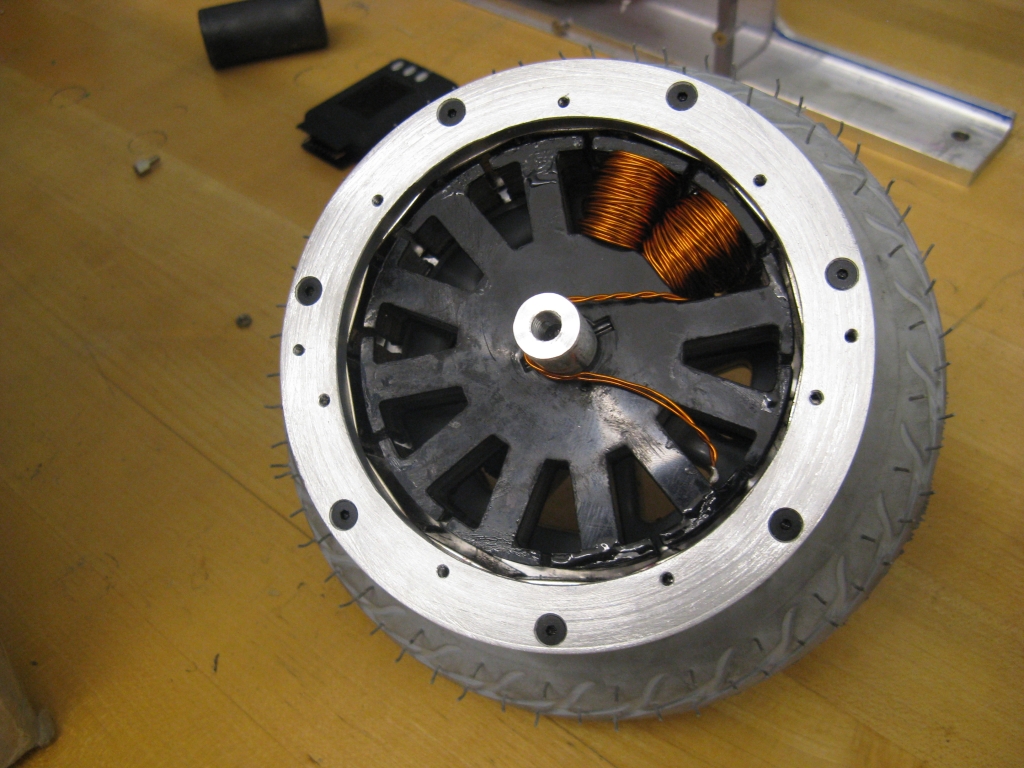
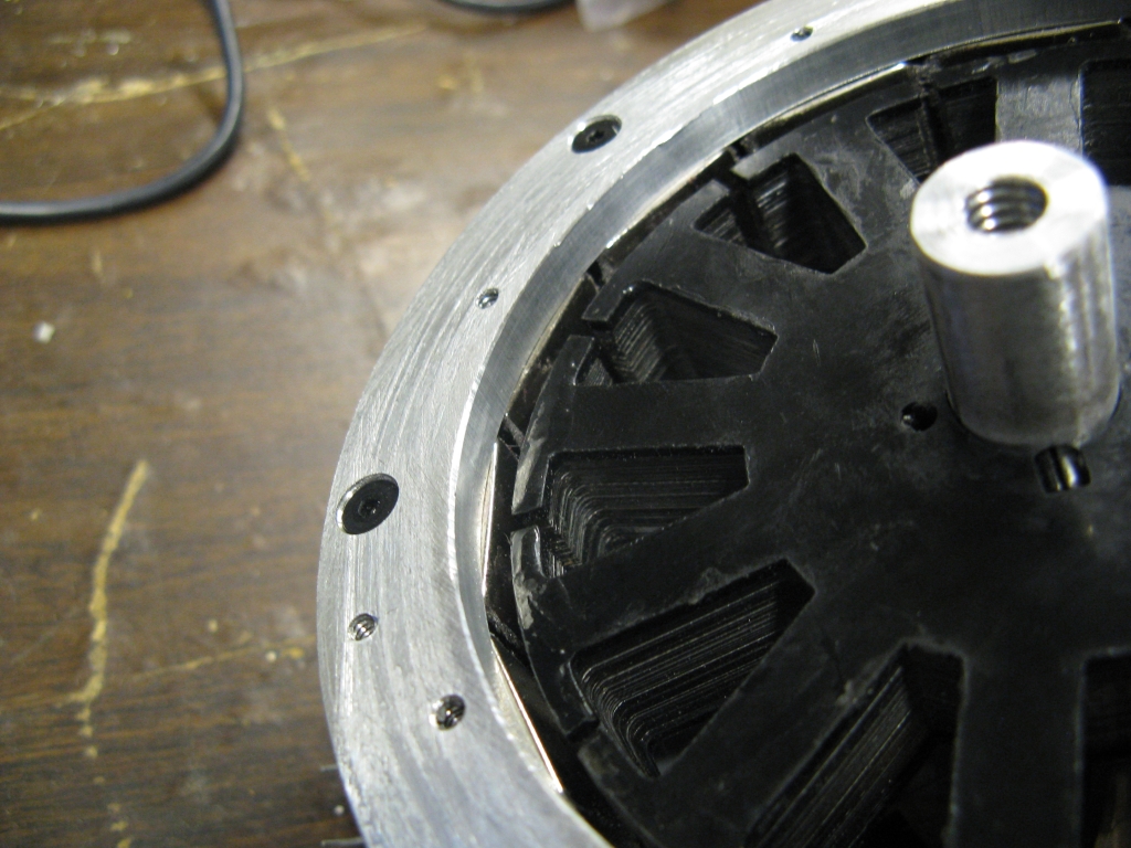
The smaller wheel is also significantly lighter due to the plastic hub. My first impression was that it would be virtually impossible to adapt this hub to a custom hub motor, since it has no flat surfaces to work with and the crappy bearings looked integral to the hub. Turns out the bearings were so crappy that they popped right out with little effort...


...leaving an actual flat and cylindrical reference surface! Somewhere to start, at least. But wait, there's more. That pocket is actually exactly the same size as the bearing pocket in BWD, so it could potentially accept the same 1/2" ID bearing. I was not planning on using the wheel rim as part of the motor structure (in fact, I was actively avoiding this), but in this case it's just so tempting. What would be required, then, is a way to attach rotor plates to the wheel itself without putting too much load on the thin-ish plastic rim. MITERS whiteboard free body diagram:

Definitely not to scale. The motor should be thinner than the wheel.

First of all, I know there are three bearings on that shaft. Let me finish, Kanye. Force from the ground goes through the tire and rim, then into the two wheel bearings and the shaft, where it is carried out to the mounting forks. (Remember, in this design the shaft is stationary.) The motor itself is merely hanging off the wheel, screwed into the rim through an adapting plate. The third bearing helps align and support the motor, but ideally should not be carrying much of the ground reaction force. I know that if the entire thing is modeled as a rigid body, this doesn't work. But in real life, accounting for rim compliance, I think this makes the most sense. (There is an analogy to power/signal ground loops in here somewhere...)

So, it's a risky mounting solution, but it would be very compact. The windings would actually stick a bit into the volume of the wheel, so it is more like an in-wheel motor than the rest so far. I would worry about using the plastic rim as an important structural component of the motor, though. And the there's also this:

...I will blatantly violate this warning (at my own risk).

Verdict: Lightweight and stealthy, but of questionable structural integrity.

Wheel Option #4: What is it?


This Edmond Wheelchair caster caught my eye, and not just because it's red. It's a latecomer to my wheel party, so I don't have a physical one to play with yet, but the Shox tire is interesting. It's a flat-free pneumatic alternative that may offer similar shock absorption, according to the website. I won't know for sure until I get it. In any case, the hub looks very similar to Option #3, so motor mounting provisions should be the same. This one doesn't have a valve stem, though, so everything is still on the table, including a completely in-wheel motor.

Verdict: Jury still out until I see it up close.

That's it for the wheel report. Next post should be the decision. I will also detail the motor plans a bit more, but it will essentially be BWD leftover hardware: