
1. Stator and rotor. Δt1
2. Deck fabrication. Δt2
3. Batteries. Δt2
4. Wind motor. Δt4
5. Motor-to-wheel adapter fabrication. Δt3
6. Optical encoder.
This is the painful step. Actually, it wasn't too bad.
Extensive lathomometer testing with a test winding of 40 turns per tooth predicted a back EMF constant of 0.190 V/(rad/s) under sinusoidal control. In RC terms, that's Kv = 50.3 rpm/V. This would give a no-load ground speed of almost 30mph at 33V. That's a bit fast, but in the right ballpark. There's really no such thing as a no-load ground speed, so in reality the top speed will be lower. But still, I decided to trade a bit of speed back for more torque by planning for 45 turns per tooth.
Interestingly, this makes it identical in turn count to BWD's rear motor. Since they have identical 2D geometry and per-phase turn counts, the only difference is the stator stack length: 0.875" for BWD and 0.625" for this motor. Shorter stator means a lower back EMF constant (or a higher Kv). BWD's back EMF constant was for six-step commutation, not sinusoidal, but should still give a reasonable estimate. From this, Pneu Scooter's motor would come out at around 0.214 V/(rad/s), or Kv = 44.6 rpm/V.
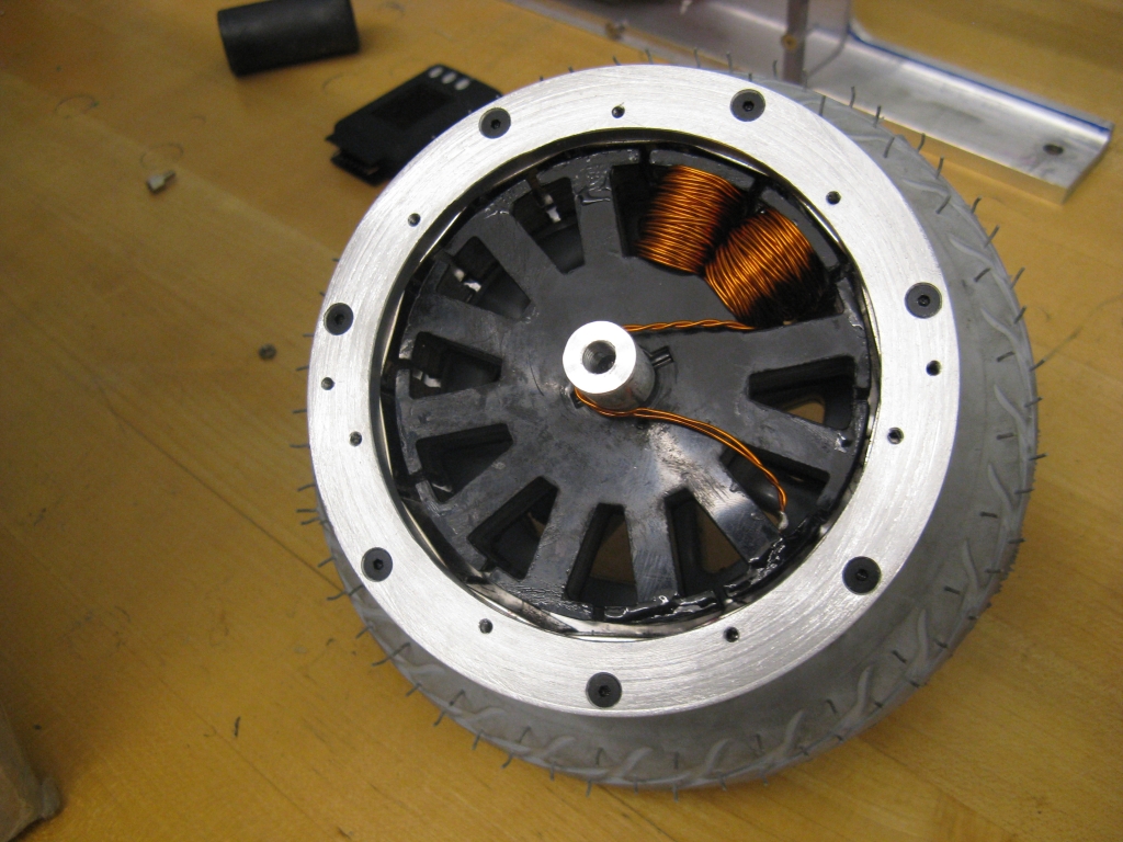
Enough math: Let the winding begin. I opted for double-stand 22AWG instead of bulky 18AWG like BWD's motor. With it, hand tension is sufficient for making the turns, so I can hold the stator and wrap it with wire rather than fixturing the stator and using extra equipment to keep tension. I've given up on ever having the patience to wind motors with perfect layers. I started each tooth with a clean layer, sometimes even two clean layers, but after that my only concern was fitting the turns in wherever they would go. Here's the first half-phase:
It's a 12-slot distributed LRK winding: [AabBCcaABbcC]. But, rather than wind Aa and jump across the stator to aA, I'm splitting it into two half motors: [AabBCc] and [aABbcC] which will then be connected in parallel "Y's" for twice the current. Turns out this is the proper way to split a dLRK winding into two parallel motors - you can't just wind two interleaved LRKs. (It took us some time pondering and reading German websites to figure that out.) If you're following, each phase will then be 90 turns of 4x22AWG wire, almost double the current-carrying capacity of BWD, which had 1x18AWG. If you're not following, maybe this will help:

No, probably not.
The idea here is that, after winding six sets of two teeth in the same manner, all the stars are connected (or, at least into two groups) and then the A's, B's, and C's are connected in parallel. To make things even more convenient, add or subtract a half-turn as necessary so that all the stars are on one side and all the A's, B's, and C's are on the other. That's what I was shooting for. Here's all but one set of teeth wound:

The last set is blocked in from both sides, so it was the hardest to fit, but ultimately it worked. The plastic end laminations do a great job of protecting the windings from the edges of the teeth, but the inside surface of the top of each tooth is relatively unguarded and a likely place for shorts. I found at least one, but luckily it went away with some shoving of wires away from the tooth top. Ideally, I would have epoxy coated the tooth tips ahead of time. But, as it is, I'll live with encasing the entire thing in epoxy while nothing's shorted.

I hate epoxy.
We didn't do this on BWD and I kinda don't like it in general. It's a bit too permanent for me. But it should offer more protection against vibration and shock knocking the windings around. It might also help with heat transfer to the core. Or it might permanently encase a mistake that will cause me to have to re-do the entire stator. We'll find out in a few days!
No comments:
Post a Comment