Wednesday, April 27, 2011

eBay Hack Charger #...idk I lost count.

It's been a while since I thought about battery charging...

...which is probably a good thing.
This might be a good time to mention that you should not take anything I say about lithium battery chargers seriously...and if you do, you are doing so at your own risk. I highly recommend buying a name-brand off-the-shelf charger and using it according to the manufacturer's instructions.

Frankly, though, my habit of going on eBay, buying the most absurd power supply I can find, and making a battery charger out of it is mostly just unfounded EVT urban legend. But I do take pride in the Cell Abuser, pictured above, which is essentially a 4V/250A power supply I bought for $100. And yes, it is attached directly to an A123 26650 cell with copper blocks and a quick-clamp. It's as close to the 8.02 ideal voltage source as you can get. The result was about as unexciting as you can imagine: the cell charged from 0 to 80% SOC in 102 seconds and to 94% SOC in 3 minutes. At the end it was...warm.

That CV-only charger was just to prove a point, though. For actual day-to-day charging of the LiFePO4 packs I use a sophisticated BMS and integrated charging system re-purposed LED power supply. The MeanWell PLC-100 and the HLG-240 lines actually make very capable 100W and 240W (respectively) CC/CV battery chargers, as I've expounded on in the past. I've been using the HLG-240-36A as BWD and Pneu Scooter's dedicated fast-charger for a long time now.

But it doesn't do cell balancing and you have to buy one specific to your pack voltage and it doesn't make cool beeping noises when it's done and and and...

Okay shut up I finally bought one of these.
Yes, I agree, it's sometimes more useful to have a charger that can handle any pack voltage and can also balance the cells at the end of a charge. For Pneu Scooter, I use separate battery balancers every...well pretty much never; it just stays balanced because A123 cells are so good. But a balance charger would come in handy when first assembling and balancing a pack. So I finally caved and bought a 1010B charger while they were in stock.

But dammit, my MeanWell was $135 and this thing was $128 and doesn't even include a way to plug it into the wall. Too bad there aren't high-current 12V power supplies available for $7...

Oh wait, there totally are.
Thanks to Sasha for the tip. This stupid thing is an obsolete Xbox 360 power supply brick. And it literally is the size of a brick, if not a little bigger. Only Microsoft needs an entire support page dedicated to a wall adapter. Apparently, it's obsolete because it's the old 203W model (12V/16.5A), but since I'm looking for high current anyway it's perfect. They're available on eBay for basically the cost of shipping.

I bought a whole box of them for $60 with free shipping.
They seem pretty easy to work with. Inside the DC output cable there are about 8 more wires than there need to be. All the yellow wires seems to be 12V and all the black wires seem to be GND. Though, there is one set of thinner-gauge yellow and black that seems kinda shady. The red and blue wires can be shorted together to turn the output on. (I guess usually the Xbox takes care of this.) A few alligator clips later and...


It's still a little bulky. If I were truly going for ultra-compactness and I had an infinite amount of money to spend, I'd get a shiny 300W TDK Lambda supply or something similar. But for basically free, this is not bad. It's better than lugging around a giant closed-frame power supply. Now, does it work?


Seems to handle a 5A charge (into a 1.8Ah LiPo) just fine. I let it run until the alligator clips started to smell funny. 

And finally, to show how it compares to the 240W MeanWell:


The 1010B/Xbox Frankenstein charger has the clear advantage of being able to handle any pack size and it can do balance charging. But the MeanWell LED sign supply still wins on size, price, robustness, and power. Verdict: I'll stick with the MeanWell for dedicated vehicle charging, but the 1010B rig will be useful for small robot packs, which vary more in size and charge current rating.

Sunday, April 10, 2011

Sensorless

I hate making excuses almost as much as I hate Toscanini's, but my project progress and posting frequency has gone way down this semester as a result of having actual work to do just to keep up with 2.007, my class on power electrons, and, oh yeah, PhD qualifier exams, Round 2. (Shout-out to all you MechE controls profs: How about a Segway problem? Eh? You know you want to.)

Doooooooo it.
Anyway, whenever it is that I am able to get back to doing real things, I've set a new target on sensorless field-oriented control. The interpolated Hall effect sensor FOC I use now works great, even at low speed, the sensor costs $3 to implement, it's mostly reliable, and it's easy to fix. So of course it's my job now to make it twitchy and unreliable, especially at low speeds, and to eat the $3 cost savings by improving the current sensors.

And there are so many ways to do sensorless control of brushless motors...

Turnigy Sentilon 100A HV
One way is just to buy a sensorless controller. Besides being a cop out, sensorless controllers like the one  above are designed for voltage-controlled RC airplane duty. They use block commutation - driving two phases and measuring EMF on the third to determine rotor position. So, no field-oriented control, no sine waves, no current limting, and only crude start-up routines. Despite all that, a large enough RC plane ESC can sometimes be made to work well for small vehicles.

And sometimes  not.
What I'm more interested in is true field-oriented control without position sensors. This means sinusoidal commutation with a high-resolution rotor position estimate, and independent control of the torque-producing current (Iq) and field-augmenting current (Id). With this type of control, all three motor phases are being driven at all times, so there is no opportunity to directly measure back EMF. Thus, a different way of deriving rotor position is required. Here's where the field diverges (lolpun) into several approaches:
  • Rotor position estimators that measure asymmetric rotor inductance using test pulses or high frequency injection. These have the advantage of working even at zero speed.
  • Open-loop back EMF or flux observers, which require a good motor model.
  • Closed-loop back EMF or flux observers, which are more forgiving.

There are at least two ways to detect the rotor position of a permanent magnet motor even at a standstill. If the rotor has saliency, its inductance is a function of electrical angle. Internal permanent magnet (IPM) motors are one good example of this, since the flux path through rotor steel changes as a function of angle. But surface permanent magnet (SPM) motors, like the ones I mostly encounter, have more-or-less constant inductance. The magnets themselves have close to the permeability of air, and the steel back-iron is rotationally symmetric.

A good sensorless algorithm could probably pick up the little magnet-retaining nubs, though...
There's another way to statically determine the position of the rotor, which relies only on the fact that motors like this operate stator teeth very near to saturation. The flux density in the most "orange" teeth in the FEMM simulation above is about 1.8T. So, driving current into that tooth's winding would not be able to increase the flux as much in the positive direction as it would in the negative direction. (Also, the rise time would be faster in the positive direction.) A clever algorithm could pick out the rotor position based on this principle.

I don't really want to write a clever algorithm, though. Measuring inductance requires good high-bandwidth current sensing, which I don't currently have, to pick out the rise time in response to a voltage step. Also, this algorithm only applies to start-up unless you use high-frequency injection to measure inductance dynamically while the phases are being driven. I'm sure there are some magic ways to do this that are cleaner than I am imagining (Rainer Nase, I'm looking at you...), but right now it's not something I want to mess this.

Moving on, then, to open-loop observers.

An observer is a control structure that attempts to recreate states which are hidden from direct sensing. Generally, an observer requires some model of the plant, so a good place to start would be a model of a three-phase brushless motor.

Engineers do it with models.
It would be nice to know the back EMF, but it's buried inside the black-box PMSM somewhere. Instead, we need to use maths:


The first maths is just stating KVL for the motor model. V and I can be measured directly, and presumably we know R and L for a given motor, so solving for back EMF, E, shouldn't be a problem. If we know the back EMF, then we know the position of the rotor. 

The second maths is an alternative open-loop observer on rotor flux linkage, which is just the integral of back EMF. This has some practical advantage over the first maths. Taking the derivative of the already-noisy current measurement will result in bad things, so even though they are physically equivalent, the smoothing integral formulation of the flux observer is more appealing in a noisy environment. Since rotor flux lines up with the permanent magnets, this also gives rotor position.

The closed-loop observers go one step further.

The motor model is only valid if resistance and inductance are known. If the model parameters are off, the estimated states will also be off. A closed-loop observer attempts to correct for modeling error with feedback. Generally speaking, the closed-loop observer goes something like this:
  1. Input the drive voltage, V, based on the PWM state.
  2. Estimate the current, i*, based on the motor model and back EMF estimate.
  3. Compare to the measured current, i.
  4. Feedback (i - i*) into the observer to modify the back EMF estimate.
"Fake motor" exists only in software.
This is less dependent on having perfectly accurate resistance and inductance parameters. The linear version of this, called a Luenberger observer, is detailed in Mevey, Chapter 7. Since I learned pretty much everything I know about brushless motor theory from Mevey's thesis, I would give a lot of weight to his particular explanation. 

There is also a slightly different feedback structure that I really like, called a sliding-mode observer. Instead of using the value of (i - i*), it uses only the sign of the error in what is aptly described as a Class D Error Amplifier, switching rapidly between a positive and a negative feedback path. The appeal of this method, covered well in Microchip AN1078, is that the switching structure clearly "eats" the current measurement noise. Right? ...... Right?

Anyway the sliding mode observer structure from AN1078 is the one I am most interested in trying, since it might even work on my existing hardware, crappy current sensors and all. The only question remaining is exactly which current and back EMF are being observed. 

Down the rabbit hole of coordinate systems we go...

Motor theory people seem to really like changing coordinate frames. Both the Luenberger observer and the sliding mode observer are most often presented as seeking the stator-frame components of current and back EMF. That is, two orthogonal components (α,β) on a coordinate plane that is tied to the stator, as opposed to (d,q) which is tied to the rotor. In a balanced three-phase system, this is a minimum set of information required to capture the state of the motor. And it makes sense to use this frame for the observed quantities because...

...because...I don't know why. They all seem to get the (α,β) flux or back EMF vector, then go back to rotor angle using an arctan function. Putting an arctan in my fast loop sounds like a horrible idea, and, excess processing power aside, I would like to avoid it if at all possible. So:

Why not observe the back EMF or the rotor flux on each phase? It's easy to do, since there are no coordinate transformations involved. The fast loop can certainly handle the numeric integration and sliding-mode compensator on all three phases. (It would have to do two components plus a coordinate transform and an arctan anyway.) But then how do you get to the rotor angle? Here is where I start digging a brand new rabbit hole...

I can get the rotor angle the same way I do now. All I need are fake Hall effect sensors for my fake motor.

Since I am observing back EMF or flux on each phase, I can easily (with if statements) detect zero crossings and flag a fake Hall effect sensor transition. This can then feed my existing controller, including the sine wave interpolation, with no modification at all. The rotor angle is calculated by the existing interpolation routine with no need for arctan. It's unconventional, which I like, but I really think it will work and it's simpler than what's out there.

So far, I'm ignoring the problem of start-up, the noisy current sensors, and many other practical issues like the fact that I can't yet program my controller wirelessly and it's buried in my scooter... I'll need to solve some of these in the near future before I can really test this out. But it's on the horizon, and now that it's in writing, I have to do it...

Saturday, April 2, 2011

EVER '11


I'm back!

EVER (the international conference on Ecological Vehicles and Renewable Energies, except with the R and E reversed because it is French) is my favorite conference EVER. Last time, the Cap Kart crew and I went in 2009, confused a lot of professors, and ate crepes. This time, Charles and I went in 2011, confused a lot of professors, and ate crepes. Oh, and test-drove an electric box thing that (probably) ran on an Arduino:


...all the Nissan Leaves were spoken for, okay?

Actually, I kinda liked it because you could clearly feel all the inner workings of the electric drive. It reminded me of the Cap Kart...you had to press an LED-lit button with an arrow on it to choose forward or reverse, and it had the turning radius of a small truck. Not sure how well that bodes for commercialization, but it was fun in sport mode, anyway.

Actually, we were there to present a paper on Miniature Electric Hub Motors, which if you're new to this game, is the key technology in Pneu Scooter, BWD, and about one third of the crazy things Charles builds. Generally speaking, the miniature hub motors are more of a fun hobby for us, but we really couldn't pass up this opportunity to disrupt the atmosphere of an academic conference with them.

Yo, where can we park these?

Oh right, I forgot to mention that we brought hardware. As it turns out, both Pneu Scooter and RazEr rEVolution fit well into checked air baggage. (I took Pneu Scooter to and from Singapore as I was completing it.) The only tricky part is the lithium batteries, but according to the TSA, one large (up to 300Wh) battery installed in a device is allowed in checked baggage. Pneu Scooter's battery clocks in at 145Wh, so I should be fine, right? ... Right?

Overall, the presentation was well-received. The chair for our session was Professor Zhu, who is sort-of like a permanent magnet motor deity. In fact, at EVER '09, he delivered the keynote presentation on fractional-slot PM motors, which is exactly the type that we tend to use for the mini hub motors. Of course, then, one of our main goals was to get Prof. Zhu to test drive the scooters.

Mission accomplished.

The academic conference was fairly standard - a lot of math. The highlight, for me, was a dirt-simple explanation of sensorless control using a flux observer that is exactly what I've been looking for. Sensorless control may be silly for EVs, but I'm still willing to give it a try just to see if I can implement it on my hardware. My hunch is that I will have to improve my current sensors a bit. (3ph 4.0?)

The best thing about bringing vehicles, though, is that we got to crash some of the concurrent events, such as the two-wheel vehicle Ride and Drive...


...and the two-wheel vehicle Acceleration Test...


...which I'm not sure we were supposed to be allowed to do. Considering that the other entries all used pedal assist (and one had more than the nominal two wheels), and absolutely none of them fit in a suitcase, the mini hub motor scooters put up a good fight. I think most people were surprised; I don't know if that's because the scooters actually kept up with the e-bikes, or if it was because they had no idea where we came from or if we were even entered in the race.

Overall, another fun trip to the weird bubblestate of Monaco. I leave you with my proposal for how all suitcases should be constructed:

Fuck little plastic wheels.

Twitch Cam

Apparently, my confused little robot Twitch, Jr. is a star on Japanese television...it's been on three different shows. (Part of the MITERS Japanese TV blitz of 2011.) But Twitch recently found its true calling in life,which is not to be in front of a camera, but rather underneath one:


Not only does it look freaking epic, but it also performs exceptionally well. The extra weight of the large camera keeps all four wheels on the ground and damps a bit of Twitch's...er, twitchy...acceleration. And since it's a (piecewise) holonomic robot, it can track in and out, side to side, or pan. Or it can switch to full holonomic mode and do all three. Here's Twitch frolicking in its newfound favorite mission:

MIT Tech TV

I'll post the on-board video when I get it (not my camera, obviously). So, the next step is to build a pan-tilt rig on top and then Surveillance Twitch will be complete...coming to an HVAC duct near you.

Tuesday, March 8, 2011

Pneu Scooter: Sensorboard v2

Hrm, all this excitement about snow scooters that don't really work when it turns out that my other electric kick scooter has done a pretty good job this winter. Except it gets really, really dirty:

Ugh.

Especially now that the two-to-three-foot mountains of snow on the side of the road have started to melt, the combination of dirty snow, road salt, and sand has become a bit of a problem. You'd think corrosion or electrical failure would have taken out Pneu Scooter by now. But in fact the only issue I've had is somebody beasting it up and down the hallway so hard that the fuse blew, taking out some critical controller hardware with it. Or some critical controller hardware blew, taking out the fuse with it.

In either case, I essentially had to replace half the active components on the controller, and the IXYS MOSFET brick. One current sensor and all? the gate drivers also ate it. After I rebuilt the controller, things seemed to be working except for one very odd new symptom: For the first 30 seconds or so of riding, one or more of the Hall effect sensors would produce sporadic faults that caused the rotor position estimator to fail and the controller to "click". 

This didn't seem like the microcontroller reset problem that I solved a while back, more like simple sensor faults. My hunch is that the same transient that killed everything else also messed with one or more sensors. And the fact that the problem consistently fixed itself after about 30 seconds of riding a) made me fairly sure it was the type of problem that I couldn't fix using deterministic troubleshooting procedures b) made me not really care. But, in preparation for the Friday Energy Showcase of the MIT Energy Conference, I decided to finally replace the sensors.

Step one was to laser cut a new sensor mount: 


The original sensor mount was made from polycarbonate and I cut the 2.5"-radius inner surface with a giant boring head in the mill. Lacking the courage and time to attempt this again, I opted for the wimpy solution of just throwing files at the laser cutter. The downside is that the first metallic object large enough to get jammed between the sensors and the wheel may just crack the acrylic right off. But the upside is that I can now put little sensor alignment features right on the part, saving me some careful measuring and gluing.

Also, t-nuts.

+ sensors + wiring + Amazing Goop =


Maybe the sensors will also be more protected from dirt and debris now that they are recessed into the plastic and potted with goop. If not, I can just hit print a few more times on the laser cutter and make a bunch of spares. Replacing individual sensors is virtually impossible, but having entire spare boards seems like a good idea given how fragile the sensors seem to be. I've also switched to the simpler, cheaper, and hopefully more reliable ATS177 Hall effect sensor.

Here's how it fits in with the wheel:


The sense magnet strip has held up pretty well. It definitely needs to be cleaned frequently, because it picks up magnetic dirt and debris off the ground, but overall it's not a bad solution for making a sensored motor without the commitment of internal sensors. As a reminder, the rubber strip magnet I used is McMaster P/N 3651K4. Some day soon I will revisit sensorless control, or hybrid control that only uses sensors at low speed. (3ph v4.0???). But for now, things are at least back to a working state.

Here's Pneu Scooter and RazEr rEVolution at the Energy Showcase:


"Does it generate electricity?"
- No, it consumes it.

"Are you selling them?"
- No.

"Do you have a business strategy?"
- No.

"Is it really saving energy if it replaces walking?"
- No.

"Do you have a card?"
- No.

Wednesday, February 23, 2011

Snow Scooter: 40 hours of work, 15 seconds of fame.


There's the 15 seconds of fame out of the way, now the 40 hours of work:

Last week, it was nearly 60ºF and the Cambridge permafrost and giant piles of snow all melted away. But they were pretty disgusting anyway, by this point. On Friday, I saw that there was a chance of a fresh coating of snow for Monday. And since I don't know what the rest of the spring will bring, I decided I might only have one chance to produce some marginally functional snow scooter. And as you can see from the video, it is exactly that: marginally functional. Or it was, for 15 seconds, until it sucked up a pebble and destroyed the left side motor. Here's how it all went down:

I finished the rear drive module a couple weeks ago, but because of me being an idiot issues with the front meta-bearing, the front drive module was left hanging. Also, the front drive module contains the Victor 883107-7 controller boxes, which needed to be water-resistant. I couldn't use t-nuts, so I had to drill and tap everything. To speed up this process, I marked all the holes in place through their matching clearance holes on other parts. Then, this:


It's actually not too bad when you have a depth setting and can just drill to a mark every time. Blind tapping sucks, but I recently invested in some nice new 4-40 plug and bottoming taps so I felt like I was putting them to good use. One problem is that, even without t-nuts, the tabs and slots still leave gaps, which are exaggerated by the taper of the waterjet. So despite everything, I still needed to seal the inside of the controller boxes with Goop to the best of my abilities:


To the controllers themselves, I added a 1/4" aluminum heat transfer plate to get heat off the bottom copper plane and into the scooter chassis, which is itself cooled by snow. In between the plate and the copper, a thin sheet of silicone thermal transfer pad provides electrical insulation while still conducting heat off the board. The board sits on 1/4" nylon standoffs (also for isolation). Here's the board in place:


I used 14AWG overcooked pasta wire from Hobby King, which turned out to be very necessary since I didn't leave much room at all for the power wiring to squeeze past the edge of the controller board. Only the absurd flexibility of this high-strand-count wire made it possible to get power to the bottom of the board. You can also see the motor wire exit strategy in that picture. Here's a closer look:


The wire runs down the body of the motor, between two of the metabearing bearings, and out of the pulley assembly through a pair of slots in the center rail. Again, only possible thanks to the magic of high-stand-count wire. Wiring the controllers was relatively easy. The controller boxes have Deans connector ports for interfacing to the outside world (battery, motors). Here's the overall layout:


A quick bench test at this point confirmed that both controllers were indeed still operational and that the front metabearing, which I violently bent back into something resembling a circle, was not totally destroyed. That's all the proof I needed to move on to the fun part, which was cutting and splicing the timing belt tank tracks. After calculating the desired track length, I cut the 2" wide timing belt (McMaster 7959K32) into two such lengths and prepared to join them into continuous belts.

One thing I learned accidentally when building my 2.007 robot way back when is that regular old cyanoacrylate (Super Glue) works disturbingly well for bonding rubber belts. I even tried commercial products advertised as rubber adhesives, but CA worked better than those, too. So I didn't bother with other adhesives this time. But in order to make a very strong bond, the CA joint needs to act in shear. This means a lap joint, and the best way I could think of to do this without increasing the maximum belt thickness was as such:


Speaking of my 2.007 robot, I found the missing tank tread and cut it up to make the rubber strips needed for the lap joint:

Poor robot.

One tread dies so that another may live:


These are both about 29.75" in unstretched length. Thanks to the giant compression springs, the pulleys should keep the belts in tension at around 25-50lbf each. I have enough room to remove one more tooth from each belt if necessary, and the tension in that case would be over 50lbf each.

Before final assembly, I made a Y-splitter for both the battery power and the throttle signal, so that one signal controls both motors. One of the goals that had to be dropped in order to meet the snow deadline was differential steering, where each controller gets a separate throttle signal and can drive the motors with different torques. The belts are so close together that I don't know how much net steering torque this would actually contribute, but it's an interesting idea that I want to try at some point. Here are the Y-cables passing through the open space between the two drive modules:


At this point, I was ready to put the belt on. Since the springs together push with upwards of 100lbf, I needed a way to hold them while slipping the belts on from the side:

Large clamp to the rescue.

The belt goes on first, then the front and rear side panels. I also made some quick bogie wheels out of 1" LDPE stock:


These take up much of the normal force on the treads, keeping them from rubbing on the bottom covers of the controller boxes. However, in the video you can see that the pulleys tend to slip a lot. Without the normal force of the tread against the drive pulley, it was hard to get enough torque transmitted. Possible solutions include more tension and sandpaper or other friction coating on the drive pulleys.

And here it is all together:


"Wait a minute. Did you just steal Pneu Scooter's front fork and attach it to snow scooter?!"

Yes. I'll give it back. But it was already snowing at this point so I had to get something on there. It's supposed to be a ski or a ski/wheel combo but for now I thought just a wheel would be fine.

I had some trouble with the belt getting sucked into one side's drive pulley. The problem seemed to be a small offset at the glue joint that was riding up on the rim of the pulley every so often and getting jammed between the pulley and the deck. The solution was to just turn the belt around, so that the small offset would move try to climb the more forgiving inboard pulley rim rather than the sharp outboard rim. If that made no sense...well just trust me.

After that, I borrowed a 19.8V FusionPack from Matthew and went outside...


And, well, you already saw what happened there. I guess the immediate cause of failure was a pebble...


...which got sucked into the thin gap between the tread and the deck, jamming the left side and burning out the (already heavily stressed) motor. The other obvious flaw was the lack of adequate friction between the pulley and the belt, which was not unforeseen and will need to be addressed. With all the weight on the bogie wheels, the pulleys prefer to just slip instead of driving the track. I think this can be easily solved. 

The more fundamental flaw is the debris protection and the fact that the motors are being run with no concern at all for overload conditions. I was sort-of imagining that the snow would cool them off, but the pulleys actually keep snow and water out decently enough that motor heating is now a problem. As for the debris, I just need some kind of brush to keep rocks and stuff out of that gap, I think.

Some parts of the design worked well, though. The metabearings did fine, even the one I mashed on the 20-ton press by accident. Overall, the 540-motor into Banebots gearbox seems to be a good solution, I just need to find the right 540 motor. Perhaps it's time to seriously consider going brushless...

Sunday, February 13, 2011

2.007 / mini4WDbot

Spring semester in MIT Mechanical Engineering means only one thing: 2.007. I'm sure there are other things going on, but this is the only one that matters. (As a TA, I may be biased.) What is 2.007? It's a class called Design and Manufacturing I. It's the original contest-based hands-on mechanical design class at MIT (back when it was numbered 2.70) and it spawned FIRST Robotics, which basically means that a huge fraction of the current and future engineering workforce can trace its roots back to the idea behind this class.

This is certainly true for me - my engineering endeavors started in FIRST when I was in high school. So by the time I got to 2.007, it was familiar territory. If anything, it wasn't challenging enough. I built this:

You can tell it's been neglected. Where is the other tank tread?!

This was back in the days where you got four gearmotors, and four levers on a panel to control them, and that was it. I elected to use only three motors: two for drive and one for the roller on the front that could suck up and spit out the contest balls. The tank treads were basically designed to last 45 seconds, which was, conveniently, the length of each match. This relatively brute-force approach was good enough to place 4th out of 120, mostly because I just learned how to drive it really well. But I don't think it stretched my mechanical or robot-building skills very much.

Part of the problem is that the kit of parts was very crude. Now, kits include a wide selection of servos and gearmotors (that actually work), as well as a user-programmable microcontroller board, so the design space is much bigger. But more than that, I think, was that even though I knew how to play the game and win, I didn't really know how to design at that point.

So how do you design? Well, as one possible data point, here's what the professors in charge of this class have come up with as an example:


This is the "director's cut." The original ending, in which the poor stair-climbing robot never quite worked right, was deemed too sad. But I kinda liked it better, since it is definitely more realistic. If you're setting out on a new design project, keep this in mind:
Failure is always an option. -Adam Savage
So yeah, you start out with the best of intentions and a very clear plan. Even so, you still wind up with a twitchy, shedding pile of parts that can be loosely classified as "robot." I think this is actually a very important learning experience that makes you realize that getting the right answer on every problem set you've ever done in no way prepares you for design. The trick is to learn enough from each failure to do substantially better the next time.

But that's not a very positive message. Design shouldn't be all about failure. It should involve other things, like inspiration and creativity. I contend that my 2.007 robot was neither particularly creative nor inspired. It kinda just was. It was "designed" to accomplish a narrow task efficiently and then fall apart return its borrowed entropy reduction resources to the world (kinda like a FIRST robot...). If you want to see something more interesting, have a look at this:


Now here's a robot that was not particularly good at accomplishing a given task. (And I don't just mean because it was destroyed by reverse polarity the day before the contest, as Charles outlines in his own 2.007 Manifesto, a must-read.) But you could literally spend hours staring at this and still not have seen all the design that went into it. In fact, I probably learned more about building robots by looking at it for 30 minutes than I did in all of 2.007. (Then again, I already started with an understanding of the basics.) 

So I guess that's the inspiration part... If you want to be good at design, go stare at things for hours and really process how and why they are the way they are. Another example of this is Twitch, Jr., which I built after staring at one YouTube video for like two years. For me at least, it's very hard to be creative from scratch. It's much easier to look at something that exists and start manipulating the interesting variables from there. After doing that for a long time, I think, you can generate ideas from scratch.

Anyway, that's all background motivation to explain why it is that I spend so much time working on 2.007 stuff during the Spring (at the expense of some of my own projects, classes, Quals, etc.). This year's game is awesome and the kit is one of the most capable ever. Thanks to some excellent EE work by Max, you can even control your robot with an iPhone now...

So, we have all this cool new stuff and I felt a bit left out with all the "simple cars" running around on the second week of class. Also, I really dislike the continuous rotation servos with cantilevered wheels, which seems to be the default drive option now. (If you know me, you know I'm all about the drivetrain...I don't really care what goes on top of it.) So, I set out to build a more drive-centric minibot base that is (more or less) 2.007 kit legal.


Okay, so you only get at most three gearmotors in the kit. But thanks to the wide aspect ratio, it would drive and turn just fine with just two diagonal wheels driven. BTW, if you want to know how to figure out if your robot will turn, read this. Also you don't get bearings in the kit. But in the interest of demonstrating good engineering practice, I've included them on the outside of the side rails. Also, I wanted to drive it off the roof (the model roof, not the real roof) and have it land upside down and keep driving.

The drive is based on four (or two, if you want to be kit-legal) Vigor BO-P5 40:1 gearmotors. We get these at some huge discount from China and, I must say, I really, really like them. The reason I like them is because they use the most creative planetary gear arrangement I have ever seen. Here's what the inside looks like:

Whaaaaa?

So, something fishy is clearly going on. In general, a two-stage 40:1 planetary gearbox would be hard to produce. Normally, that would take three stages, unless the sun gear was tiny, which it isn't in this case. So what is this? Best I can tell, it is called a differential planetary gearbox. (Not to be confused with a planetary differential.) The ring gear of the second stage is the output, and a difference in the number of teeth between the first and second stage ring gears produces a high reduction ratio in one stage. This bears some resemblance to harmonic-drive gearing, but in nice non-flexy planetary form.

So, the first stage is just a regular planetary reduction, with a 12T sun gear and a 45T ring gear. This gives a first stage reduction of 1+45/12 = 4.75:1. Two sets of 16T planets of different pitches are connected to each other in one planet carrier. The second stage ring is 51T. The ratio of the second stage is 51/6, where 6 = 51-45. Every time the planet carrier goes around once, the 51T second stage ring moves 6 teeth. So, the total ratio is 51/6*(4.75) = 40.375. It works just as well for the higher ratio 120:1 BO-P6 motor, though obviously with different numbers. 120:1 in two stages! Is that not the coolest thing you've ever seen?

Gearbox porn aside, I opted for the 40:1 and 2-5/8" standard servo wheels for a top speed of about 2fps, which is slow in most robot contests but relatively fast for 2.007. I figured it would have a ton of torque and be very controllable, though. Also, there is no other option. These can be hacked to remove the second stage entirely, but a 4.75:1, 20fps robot would not have enough torque to do things like..turn or maybe even move.

I have class at 8AM on Thursday morning, so I decided that I would spend all of Wednesday night building this.


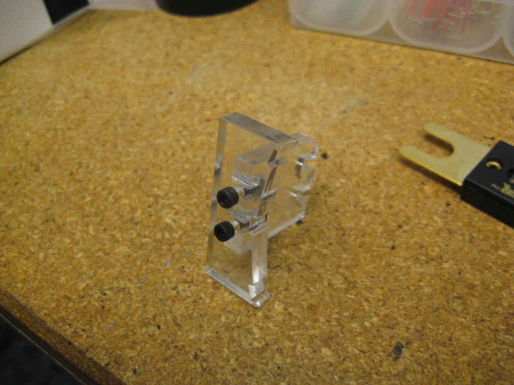
Really, there are only two unique parts that require thought. The side rails are made from kit 1/16"-wall 1"x1" aluminum extrusion. Originally, I designed simple 1/2" wide slots, but then later I realized that, even though there were no interferences in the final state, I couldn't actually assemble it without having wider 7/8" slots where the wheel hubs were. The wheel hubs are made from kit 1" Delrin round stock, turned down and tapped for a 4-40 bolt pattern:


The Delrin hubs fit on the motor shaft and also into the outer bearings...

...like so.

Here's what the robot looks like assembled, circa 3AM:


The base is an 8"x8"x1/4" ABS sheet with rectangular cutouts for the wheels. The motors are face-mounted into the inside of the side rails using 2-56 screws. Amazingly, it is possible to screw the motor on with the wheel and hub in place. The allen wrench fits through the matching hole on the outside of the rail, through small opening in the wheel, just barely past the hub, and to the motor mounting hole.

I assure you this was intentional...

And here it is circa 7AM, wired and ready to go:


It's powered by a cute 7.4V 500mAh LiPo from HobbyKing (kit legal). The controller is...well it's something I don't want to talk about. The motors are driven by four Vigor VS-11 servo guts. The VS-11 is the massive 1/4-scale servo that Twitch uses to brute force its linkages around, and is also 2.007 kit legal. Turns out you can rip the ~2A motor controller out of them and it's still cheaper than anything else you can buy to do the same job.

You might notice it's missing the wheel-mounting screws in the above picture. If I'm to be perfectly honest, I first tried some adhesive solutions but of course they failed miserably and I had to go back and add screws later.

And there you have it, mini4WDbot in under 24 hours. I don't know why I wanted one, but now that I have it I can't stop playing with it. It's just immensely fun to drive. It can drive upside down. It can handle a bit of payload. It can be controlled by radio receivers, a USB gamepad controller, or maybe someday an iPhone. Why have I not built any general utility minibots before?!