Showing posts with label twitch. Show all posts

Sunday, July 23, 2017

Link Update (Again) and Bonus Link Trig!

Once again, all my documentation permalinks got broken when Google Drive stopped supporting static URL hosting. But, I've transferred everything over to AWS now and gone through updating links accordingly on all the static project pages and a few select posts, especially this one. Hopefully these permalinks last a bit longer! Here's the full directory: https://scolton-www.s3.amazonaws.com/list.html. I may transfer more stuff over to there as I go, including maybe using it for hosting new static project pages. Still learning my way around AWS.

Speaking of links, here's an odd bit of trigonometry to solve last post's linkage mystery:

For Twitch X, I mentioned that rather than solving the trig for the geometry of the linkage that connects the two sets of diagonal wheels together (the sin/cos link, as I called it), I came up with a weird exponential parametric equation for the two angles:
x = [sin(θ1)]^K = 1 - [cos(θ2)]^K
The value x ranges from 0 to 1 as θ1 and θ2 both sweep from 0º to 90º, albeit on different trajectories. It makes an excellent feedback variable for the controller, since it can be derived from a simple weighted average of the two linkage angle sensors (after trig and exponent). And conveniently, x = 0.5 is where the wheel sets are perpendicular, for omni mode. For the link lengths used on Twitch X (L1 = 1.00in, L3 = 7.50in), I experimentally derived K = 1.23456789...no joke. But I wasn't ever convinced this was an exact solution, and as it turns out it isn't.

A few pages of trig later, this is the actual parametric solution:
L3*[cos(θ2) + sin(θ1) - 1] = L1*sin(θ1 + θ2)
This one's a lot less convenient from a control standpoint: since θ1 and θ2 are on both sides of the equation it's not obvious what to do with the wheels based on measurements of the linkage angles, at least not without further math. But this is the geometrically accurate solution.

What's amazing is how close the other parametric equation is. As it turns out, the max error is just over 1º and the value K = 1.23456789 is actually a pretty good one in terms of the average error over the full range from 0 to 90º:


None of this matters as far as Twitch X control software is concerned - the exponential approximation with θ1 and θ2 separated is still far better for the application. But solving the mystery of the sin/cos link was really interesting.

Thursday, May 3, 2012

Cambridge Mini Maker Faire + Kramnikopter

A couple weeks ago I went to the Cambridge Mini Maker Faire. It's a smaller event than the full-scale NY Maker Faire I went to in September, but it's much closer to home. In fact, it's within walking distance, so I decided to kart everything over.

Yes, kart.
It turns out that tinyKart makes a pretty good hand truck. Also along for the ride was Pneu Scooter (ziptied to the frame), Twitch, and 4pcb (in the seat). Unfortunately, the Mini Maker Faire is too crowded for the vehicles to be effectively (or safely) demo'ed. And it was too windy to fly 4pcb.


So that just left one option:

Balloon Twitch.
You can see how windy it was by how far the balloon is deflected. The balloon was my way of making sure that nobody stepped on Twitch accidentally, but it also made the robot a lot more "interactive". And by that I mean that several little kids were teased.


Sorry for the blue video...forgot to turn off manual white balance...

You can find more photos from CMMF 2012 in the Flickr pool.

I was really looking forward to demo'ing 4pcb, since it drew so much attention at the NY Maker Faire despite not actually being flyable at that point. It's small enough not to pose much of a safety risk, but micro quads really don't like wind. In general they're twitchy and hard to fly. Giant hexrotors have the opposite problem: they're very stable, but too dangerous to use anywhere near people.

To fill the gap in my flying things fleet, I decided to put together a Turnigy Talon frame from Hobby King. I got to fly one that was put together by Daniel Kramnik (of Tesla Coil fame) and was very impressed with the quality of the frame. For $34, you get a real carbon fiber + aluminum frame. Add to that four $7 motors, four $14 ESCs, and $18 battery, a $3 bag of props, and $15 control board, and you get a complete mid-size quadrotor kit (bring your own radio) for $154.

Kramnikopter!

Here it is with 4pcb propped on it for size comparison:


The Talon frame is very impressive, even without considering the cost:performance ratio. It's stiff and light and it looks amazing. It also seems very durable - you'd have to crash pretty hard to break it and the landing gear is nice. When you take into account the fact that it's $34, it is one of the best deals I've seen.

The motors, on the other hand, leave something to be desired. They are the most inexpensive of an already low-cost/low-quality brand name, which means they have some issues. Mostly, I ran into axial alignment problems - the can and shaft are poorly constrained. They are also not balanced. If I were to replace one component right now, it would be the motors. They do look cool, though. 

For what it is, the KK board is an impressive deal as well. It's rate-mode only, so it can't do self-leveling, position hold, altitude hold, or any other more advanced features. 4pcb flies in self-leveling attitude mode, so returning the sticks to center means it tries to go to level (zero angle). So it took some practice for me to learn how to fly Kramnikopter in rate mode, where returning the stick to zero means zero angular velocity. You can see me learning the new input mode a little at the start of this video:


After filming the first half of that video with it, I decided to go ahead and attempt to fly my HD video camera. I have a long history of attaching my camera to things that move, but this would mark the first time that it's actually left the ground. The mount I made was pretty simple:

Kramnikam v-1.0
On one hand, the camera flew and survived. But it's not quite a cinematic experience yet. This camera weights exactly 300g, and it's just a little bit too heavy for this combination of motors and props. The resulting flight is very close to being unstable, since the motors are almost maxed out. The more obvious problem is that my initial vibration isolation solutions (foam tape, felt) didn't help much. So, lighter camera and softer mount seem to be the next steps. For now, I have a really nice medium-sized quad to play with.

Tuesday, September 20, 2011

Maker Faire NY 2011

Last weekend I went down to the World Maker Faire in New York, along with some of the other builder-types from MIT and the Summer Engineering Workshop crew. Needless to say, we were responsible for most of the rideable objects on our side of the Faire:


I've been to the Cambridge Mini Maker Faire twice, but this was my first experience with one of the three World Maker Faire events. While the Mini Maker Faire probably attracts a crowd of a few thousand, the World Maker Faire numbers must be in the several tens of thousands. First off, I was amazed that a handful of people actually knew me from my blog, so here's a shout-out to the people who came by my table to say hi. I'm not as famous as certain people, but it's cool to meet my blog readers in person.

Also present was Max H., who brought TOBL to show off, and most of the tinyKart crew. A large sampling of the MITERS builders came down from Cambridge as well to show off a pair of sound-reactive EL shutter shades, giant Tesla coil driver, 3D printer, battlebot, tankboard, hub motor kick scooter, eddy current clock, and rideable freakin' hexapod.

For my part, I decided that I would attempt to bring five projects. First, my three Maker Faire veterans, Pneu Scooter, Twitch, and SegStick. Additionally, I brought 
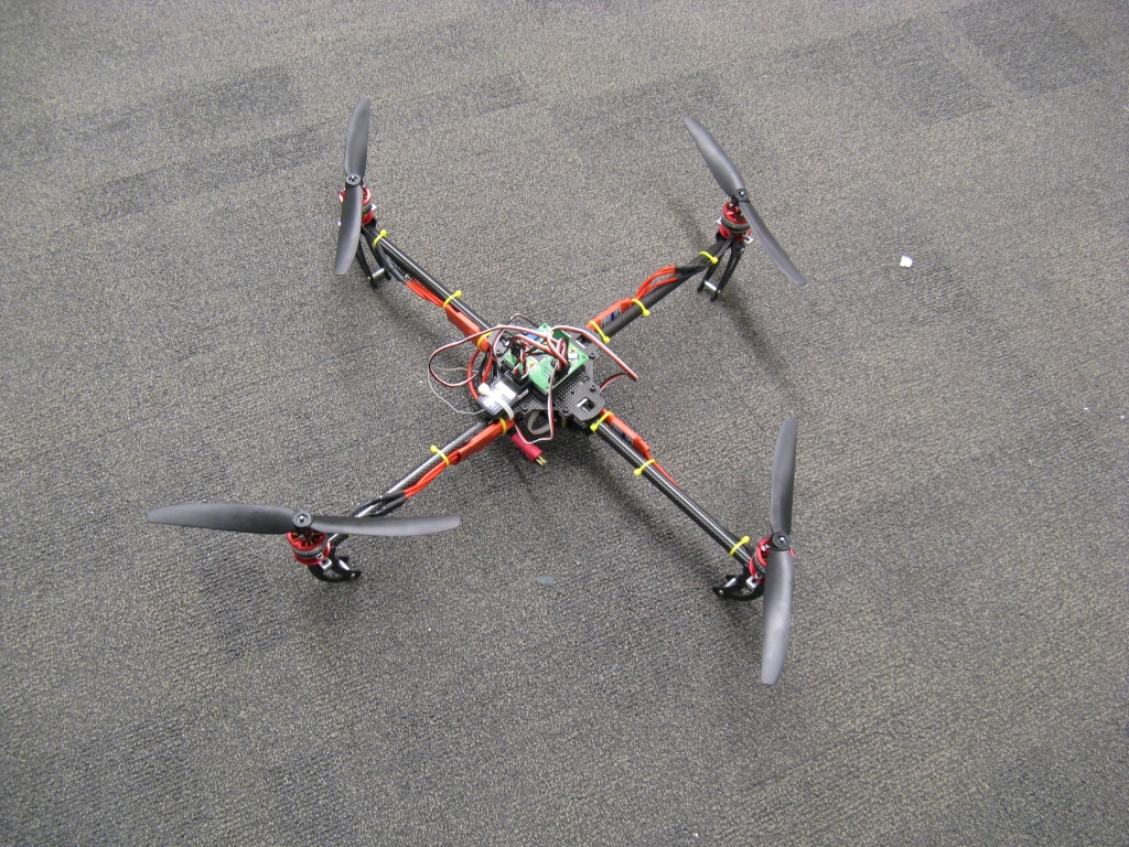
4pcb, which turned out to be an attention-getter even though I did not even attempt to fly it. I would say that quadrotors are the new Segways - the current obsession of every random tech-savvy person. But in fact, Segways are still the new Segways. For some reason, no matter what else I bring, I can't escape the Segway people. Then again, I've said a few times that the quadrotor is just two Segways and a FIRST robot, so maybe it's all inherited from one parent class of silly self-stabilizing objects.

So before I get angry, Yes, it does have an angular rate sensor, commonly known as a "gyro" for historical reasons. No, there is no mechanical flywheel keeping it balanced. No, it does not use a Kalman filter. And yes, it runs just fine on an Arduino, and it doesn't even use that much of its processing power because the code is very, very simple...much simpler than you want to think.


And that's all I want to say about quadrotors and self-balancing platforms. But here are the Maker Faire recaps for the more interesting projects:

tinyKart:


That's tinyKart in the trunk of a Ford Fusion. I loaded it into the trunk myself in about 10 minutes. It involved taking out 12 cap screws and sliding the two halves apart, then flipping the front half over so that the steering wheel rested in the seat. The back half weighs less than 40lbs and the front half weighs less than 20lbs. There was even enough extra room in the trunk for Tyler's monster Tesla coil driver.


In terms of making an ultralight, ultra portable go-kart, I consider this trip a huge success. We like to make things that don't exist, and an ultralight electric go-kart is something new. There is the Razor Ground Force, which is the same weight (55lbs) as tinyKart but there really is no comparison. Which brings me to my next point:

tinyKart is absolutely freaking awesome as a go-kart. 

Just look what reverse did to this dude's hair...
We drove it all weekend and it is actually amazing to me that we built such a thing from scratch. It's a totally different experience from Cap Kart and most other go-karts I've driven, and it's more fun than any of them. "Sprightly" might be a good word. I really don't know. It darts around in ways that defy its narrow tires and flex-y frame. The acceleration is good too, despite the lack of more formidable brushless motors. The trigger throttle just makes it even more of a unique experience. And the brakes are so good that I worry about bending the steering wheel from the deceleration force. I really would not change a single thing about the mechanical design...it's pure win.

"If it's going to break, it's going to break now." -Max
It even does things it shouldn't, like off-roading. We took it on slippery grass and dirt, and it was even more fun than on asphalt. The flex-y frame doesn't mind at all and the 17mm aluminum wheel axles, which are probably the weakest link in the structural loop, survived both the shock load from bumps and side load from drifting.

Pretty much the only things that isn't 100% perfect are the controllers. Maybe I just have a high standard for motor control...well okay, I definitely do...but the Kelly controllers just aren't quite up to the task of driving full load into these motors. They cut out occasionally, leaving you with half power for a second or two. I'm learning the acceleration threshold that works, but the motors can handle more power so I feel the urge now to give tinyKart a set of controllers that can, too.

Pneu Scooter:

A few days before Maker Faire, Pneu Scooter got a flat rear tire. I knew it would happen eventually because the front tire got a flat about a month ago. Unfortunately, the 6" pneumatic casters are not conducive to easy tire/tube changes. I thought they would be, which was one of the motivators for using pneumatic tires in the first place, but as it turns out, barring special tooling, it's easier to change the entire wheel. So changing the rear wheel means taking apart the hub motor. But, really, Pneu Scooter has been ultra-reliable, so this is more like scheduled maintenance than a design flaw.

Could use a cleaning while I'm at it...
So I opened the motor for the first time since it was built. The process is pretty simple. The only tricky part is getting the three phase wires out, since they are soldered to connectors. To fit back through the bearing, they needed to be de-soldered and shoved back into the axle slot. Here are some pictures from the teardown, with everything dirty but intact:

Windings.
Outer spacer.
Dirty rotor.
Awesome adapter ring.
After taking off the adapter ring, I could get a good look at the rim and tire to see where the damage occurred. I suspected that the tire and tube had been punctured by screws that hold the ring onto the plastic rim. (The front tire suffered a similar failure.) Sure enough, I found a bunch of slashes like this:


I guess the screws were wearing through the tire and eventually the tube over time. The solution is so simple that I have no idea why I didn't do it in the first place.

Duhhhh...
So I put the motor back together with the shorter screws and Pneu Scooter was back up an running in less than three hours...


...which is great, because it actually came in really handy during Maker Faire. Not only was it the only one of my vehicles that I actually felt reasonably safe letting the annoying little kids ride, but it turned out to be the best way to get from the Citi Field parking lot to the Maker Faire itself. There were shuttle buses, but they were crowded and only took you about 60% of the distance anyway. So, I just took the scooter instead.

Twitch

Twitch also had some lingering wheel problems before Maker Faire. Specifically, the press fit holding the custom aluminum hubs to the plastic Vex omniwheels had failed on one wheel, making it hard to drive. It's happened before and I've resorted to epoxy for a quick fix, but I wanted to make a more permanent solution before the Faire. So, I manned up and got on the lathe...


...and then the mill...


... to turn out some new hubs that will actually bolt onto the wheel instead of relying on a press fit into flimsy plastic. The six-bolt pattern lines up with the spokes such that 1/4-20 screws rest against the inside surfaces to positively transmit torque to the wheel. I only put on one new hub for now, but I have the full set for when the remaining press fits fail. 

As I was doing this, though, some other problems revealed themselves. One of the linkages had a stripped-out hole, and one of the servos that drive the linkages was also damaged. I suspect both were symptoms of the wheels running into hard stops while the servo continues to drive the linkage. So far, I've only been calibrating the servos by hard-coding in soft-stop values, but they change every time I take the robot apart and put it back together.

Twitchguts, if you don't remember.
I decided that after replacing the servo and fixing the linkage, the best way to prevent this problem from happening again would be to just write the damn trim software the way it should be written.


Now the servos each have a software-settable minimum and maximum value. Through some coding trickery I was able to "or" the calibrate state with the normal drive states (forward, sideways, omnidirectional) so that you can trim the servo end positions while in any one of the states. This is useful since the servo maxima occur in the forward state and the minima occur in the sideways state. And just for extra software hacker cred, I save all the trims to a text file that automatically loads when the program starts up.

Twitch was, as usual, a constant source of entertainment that filled in the gaps well while the vehicles were charging. Part of the fun of Twitch is that nobody (or very few people) have ever seen a robot move the way it does. I am finally able to drive it in the way that it deserves, making smooth state changes and combining rotation and translation in ways that just look cool. It took a lot of practice, but I feel like Twitch is finally living up to its potential. And on that note I'll just leave this here...


Saturday, April 2, 2011

Twitch Cam

Apparently, my confused little robot Twitch, Jr. is a star on Japanese television...it's been on three different shows. (Part of the MITERS Japanese TV blitz of 2011.) But Twitch recently found its true calling in life,which is not to be in front of a camera, but rather underneath one:


Not only does it look freaking epic, but it also performs exceptionally well. The extra weight of the large camera keeps all four wheels on the ground and damps a bit of Twitch's...er, twitchy...acceleration. And since it's a (piecewise) holonomic robot, it can track in and out, side to side, or pan. Or it can switch to full holonomic mode and do all three. Here's Twitch frolicking in its newfound favorite mission:

MIT Tech TV

I'll post the on-board video when I get it (not my camera, obviously). So, the next step is to build a pan-tilt rig on top and then Surveillance Twitch will be complete...coming to an HVAC duct near you.

Monday, August 16, 2010

Auto-Gyro-Twitch

You can probably tell from the first video that Twitch, Jr. is not the easiest robot to drive. Trying to remember which way is forward is just the beginning of the problem. (Which way is forward?) There is also bit of variance between the relative speeds of each motor under the same nominal command. This gets exaggerated by the 4WD omni wheel configuration, especially on an uneven surface.

Here's where a gyro (yaw rate sensor) comes in handy. These tiny MEMS sensors measure angular velocity and produce an analog signal. The signal can be processed by a controller for tasks such as self-balancing, or level flight. In the case of Twitch, I really just want it to keep the robot on a fixed heading unless I tell it to rotate. This should be a simple feedback controller. I learned about that in 2.00...wait actually I did it in high school.

 Lol.

Anyway, six years of training later and it shouldn't be that hard to create a yaw-rate stabilized robot, right? Right?

Well, where do I start? First problem: Twitch's original control mapping software resided on the transmitter side, in the Visual Basic program that interfaces with the USB gamepad. In order to integrate the yaw-rate control loop, the entire mapping algorithm, including the state machine that sets which driving mode is active, had to be moved onto the microcontroller. Okay, this was mostly just tedious, not really difficult. Then I soldered on some more headers in empty protoboard space and added the sensor, a Sparkfun breakout of the LPY530AL 300º/s gyro.

Except, Twitch has a densely-packed electronics bay already, so it's gonna be a tight fit.

 See the headers?


Things had to bend a little, but everything seemed to still work. So, I uploaded the new mapping code with the yaw rate control loop and put it on the ground for some testing. After swapping to sideways mode, though, the receiver radio died. :( I've only killed an XBee radio once before and that was by applying 12VAC to it... So something very bad must have happened. Upon further inspection:


There you can see the radio and a small bit of the gyro in the upper-left corner of the image. You can also make out the plastic back of a Mabuchi motor and a piece of electrical tape. The electrical tape I put there later to cover the exposed motor terminal, which happened to just barely intersect the 3.3V and GND pins on the gyro when the motor swung over into sideways mode. So, the switching 8V line to the motor got momentarily switched onto 3.3V and/or GND. Amazingly, the gyro survived. But the radio did not. After bending the tab out of an interfering path, covering it with electrical tape, and replacing the radio, Twitch was back in business:


The yaw-rate stabilization definitely helps. By request I also added a mode that automatically selects the wheel position based on where the translation joystick is. Actually, this is how I meant to do it originally, I was just lazy and had buttons for changing wheel positions instead. But, now it's much closer to fulfilling the original vision.

Tuesday, July 13, 2010

Twitch, Jr. - Did I mention I like driving robots?

It's true. I think I like driving them more than I like building them. That was the real motivation behind this project. Some time ago, I saw this video of the original Twitch, made by FIRST Team #1565, and I decided that it would be just about the most fun robot to drive ever. It's not quite an omni drive, even though it has omni wheels. Nor is it a crab drive. It's a linkage drive. The wheels are constrained to move together by a set of linkages. I guess it doesn't offer many advantages over other omni drive configurations. But come on, it's awesome!

So I set out to build one a while back. A small one. With no particular use for it in mind. It's so arbitrary that I couldn't decide on what size to make the main chassis, so I chose letter 8.5"x11". (But is it portrait or landscape?) Anyway, I got to the point where I saw that it would all go together nicely and then realized that I should probably finish my thesis and get through 2.007. All that was left was...well, all the electronics and programming... Now that it's summer, I have no excuse not to finish.


I thought the wiring would be hard, given the number of moving parts inside the Twitch sandwich, but it actually wasn't that bad. I converged on a clam-shell-like wiring layout: you lay all the interconnects from the top panel to the bottom panel along one edge. This allows easy assembly and disassembly without detaching wires.


Here's another view.  The motor controllers are Pololu Trex modules, which I am very pleased with. The monster 1/4-scale servos are Vigor VS-11's. These are the servos we used for 2.007. They are ultra high-torque...like, over 1Nm. More than their equivalent Hitec servos. But as a consequence of that, they also draw a ton of current. Like, 2-3A each at full load. For that reason, I got a 7.5A BEC to power them. The only problem is, the microcontroller's LDO regulator is fed by the same 6V bus. And there isn't enough capacitance at the output of the BEC or in the servos to adequately decouple the switching. I found this out when Twitch started...well...twitching...under load.


Cue massive amounts of capacitance. 3300uF on the 6V bus, plus another 1000uF following the input diode on the line that feeds the microcontroller's LDO regulator.

Finally, it was time to close up the clam shell. Thanks to some serious Design For Assembly, I left myself an access hole so I could tighten the final servo horn screw with the clam all closed up. Unfortunately, I made the hole too small, so I still had to open everything, drill it out, and try again.


And that's that.. And this is the first test-drive:

Tuesday, May 11, 2010

Twitch, the part where I try to build something.

Twitch (or, Twitch, Jr., since the original Twitch was much bigger) is finally underway. (I decided it would be a good idea to finish writing my thesis first so I could graduate.) It should be a relatively quick project, especially considering that I got most of the important parts sent out for water jet cutting.

Mail-order robot.

Actually, this is the first time I've tried to make a drive like this, with so many moving parts. Here's a quick reminder of what it should look like:


Both sets of diagonal wheels are coupled by parallelogram linkages. The two wheels on each side can also be coupled by a cross link as well, though with two linkage drive servos this is not entirely necessary. The most critical pieces are the bearing blocks that support each wheel and motor module. These are made from Delrin for low friction and ease of machining. There are a total of eight, for four wheel modules:

Four identical wheel modules, mounted in the corners.

The bearing blocks sit on aluminum posts, hopefully aligned correctly between the top and bottom plates. With the two diagonal linkages in place, the wheels can be moved in pairs. Normally, both pairs will be moved together to switch between the "long" and "wide" orientations.

 "Long" orientation (top) and "wide" orientation (bottom.)

Besides these two orientations, there are other possibilities. One is to put all four wheels at 45º. Another is to put one set "long" and one "wide." Since they are omni-wheels, either of these would be capable of full 3DOF movement. If the cross links are used to couple the two diagonal sets of wheels, the range of intermediate wheel positions is more limited. Needless to say, this project will become an exercise in input mapping and control at some point.

For now, though, there are still a few mechanical details to work out. After the first assembly, it's clear that there is a bit too much friction in the wheel module bearing blocks for the servos to drive the linkage. They were made to be fairly tight, for stiffness, but after seeing it in real life I think I would trade a little slop for less friction. Unfortunately, this linkage gives the servo the least amount of mechanical advantage at the extremes, so if the bearing friction is constant, the servo sees the most torque at these points. I'm crossing my fingers that it's actually the wheels, driving against each other during the transition, that can create the torque for overcoming this friction. (Again, why does everything converge to a controls problem?!)

Next step is creating hubs for the Vex 4" omni-wheels that allow them to attach to the gearmotor shafts. Then, wiring and programming. Okay, so it wasn't quite a two-week job, but it's progressing.

Thursday, April 22, 2010

Twitch, Jr.

Guess what? I'm actually going to build something that isn't a motor or a motor controller. It's been a long time since I actually built a robot, but seeing a fair number of 2.007 robots coming to life makes me want to execute a good old-fashioned two-week robot build. Okay, so I'm not really going to build a whole robot, just a drivetrain. That's all I was ever good at, anyway. I've built many different types: 2WD, 4WD, 6WD, skid-steer, tank treads, mecanum wheels. But I've never built a linkage drive! What is a linkage drive? It's this:


This is the drive from FIRST Team 1565's 2008 robot, "Twitch...the missing link(age)." I am not affiliated in any way with Team 1565; I just think their linkage drive is awesome.

It doesn't have complete...uh oh time to make up a word...holonomicity? In other words, it can't go in any arbitrary direction at any time like mecanum wheels or a swerve drive. But it can rapidly swap between two perpendicular directions of travel, which is very practical. It has omni-wheels, but only just to allow it to turn and swap axes smoothly without skidding wheels sideways. Consequently, it can coast into turns as it swaps axes, which I think makes it incredibly fun to drive.

So, I'm going to make a (small) linkage-drive robot. Here's a quick video of the linkages in action:


Sorry for the awkward cropping...click the full-screen icon for a slightly better view. For a sense of scale, those are ~4" wheels. (They are really these awesome Vex omni-wheels, but I'm too lazy to add the rollers into this existing wheel model I found.)

Top View

The four identical wheel+gearbox+motor modules are mounted in plastic bearing blocks that rotate on upper and lower posts. The two long, diagonal links do most of the work, linking opposite corners to each other so that diagonal wheels are always parallel. The short links (one of which is redundant) couple the two sets of diagonal wheels in a strange and somewhat frightening way. (Frightening in that it comes kind-of close to singularity at the extremes.) That's why I left open the option of using two servos to drive the two diagonals independently. But in theory the entire mechanism has just one degree of freedom.

The gearmotors are 36mm, 20:1 BaneBots planetary sets. The controllers (shown as nondescript green blobs) are Pololu Trex modules. The structure is mostly an aluminum sandwich, with the plates and links being cut with an abrasive water jet. And yes, I sent the parts out despite the fact that MIT has seven waterjets on campus now. Cue rant: Of the seven, only one is open for general use and it's not currently working...plus sending it out is fairly cheap, believe it or not. (If you don't happen to go to a school or work at a company that likes to spend money on underutilized and difficult-to-maintain machine tools, here's one good place that will cut your cool robot parts quickly and cheaply.)

Future robot.

More parts arrive this week, so I should have a robot by next week. If you're wondering about the control...I have no idea how to do it yet. But I'm not really worried. I'll write it in Visual Basic just to annoy everyone. Shouldn't take that long. (Really.)

I just feel like there's something else I'm forgetting to do...oh right my thesis!