Showing posts with label 4pcb. Show all posts

Friday, June 1, 2012

4pcb Instructable


I finally got around to creating an Instructable for my PCB Quadrotor. 4pcb is a "low-level" build, perfect for people who don't like black-box components and want to do everything from scratch. But it's also simple to put together and Arduino-based for easy coding. I'd love to see a swarm of them flying around some day, but I really want to see derivative designs, like a hexrotor version!

I've updated the documentation on my own 4pcb page to redirect to the Instructable as the primary source of information for how to build it.

In other news, Talon hexrotor!


For $75, you get about $300 worth of carbon fiber and machined aluminum parts that fit together into a 625mm hexrotor. I won't be doing much with it for a while, since I have to get my huge hexrotor flying with custom ESCs, but I couldn't pass up the deal.

Thursday, May 3, 2012

Cambridge Mini Maker Faire + Kramnikopter

A couple weeks ago I went to the Cambridge Mini Maker Faire. It's a smaller event than the full-scale NY Maker Faire I went to in September, but it's much closer to home. In fact, it's within walking distance, so I decided to kart everything over.

Yes, kart.
It turns out that tinyKart makes a pretty good hand truck. Also along for the ride was Pneu Scooter (ziptied to the frame), Twitch, and 4pcb (in the seat). Unfortunately, the Mini Maker Faire is too crowded for the vehicles to be effectively (or safely) demo'ed. And it was too windy to fly 4pcb.


So that just left one option:

Balloon Twitch.
You can see how windy it was by how far the balloon is deflected. The balloon was my way of making sure that nobody stepped on Twitch accidentally, but it also made the robot a lot more "interactive". And by that I mean that several little kids were teased.


Sorry for the blue video...forgot to turn off manual white balance...

You can find more photos from CMMF 2012 in the Flickr pool.

I was really looking forward to demo'ing 4pcb, since it drew so much attention at the NY Maker Faire despite not actually being flyable at that point. It's small enough not to pose much of a safety risk, but micro quads really don't like wind. In general they're twitchy and hard to fly. Giant hexrotors have the opposite problem: they're very stable, but too dangerous to use anywhere near people.

To fill the gap in my flying things fleet, I decided to put together a Turnigy Talon frame from Hobby King. I got to fly one that was put together by Daniel Kramnik (of Tesla Coil fame) and was very impressed with the quality of the frame. For $34, you get a real carbon fiber + aluminum frame. Add to that four $7 motors, four $14 ESCs, and $18 battery, a $3 bag of props, and $15 control board, and you get a complete mid-size quadrotor kit (bring your own radio) for $154.

Kramnikopter!

Here it is with 4pcb propped on it for size comparison:


The Talon frame is very impressive, even without considering the cost:performance ratio. It's stiff and light and it looks amazing. It also seems very durable - you'd have to crash pretty hard to break it and the landing gear is nice. When you take into account the fact that it's $34, it is one of the best deals I've seen.

The motors, on the other hand, leave something to be desired. They are the most inexpensive of an already low-cost/low-quality brand name, which means they have some issues. Mostly, I ran into axial alignment problems - the can and shaft are poorly constrained. They are also not balanced. If I were to replace one component right now, it would be the motors. They do look cool, though. 

For what it is, the KK board is an impressive deal as well. It's rate-mode only, so it can't do self-leveling, position hold, altitude hold, or any other more advanced features. 4pcb flies in self-leveling attitude mode, so returning the sticks to center means it tries to go to level (zero angle). So it took some practice for me to learn how to fly Kramnikopter in rate mode, where returning the stick to zero means zero angular velocity. You can see me learning the new input mode a little at the start of this video:


After filming the first half of that video with it, I decided to go ahead and attempt to fly my HD video camera. I have a long history of attaching my camera to things that move, but this would mark the first time that it's actually left the ground. The mount I made was pretty simple:

Kramnikam v-1.0
On one hand, the camera flew and survived. But it's not quite a cinematic experience yet. This camera weights exactly 300g, and it's just a little bit too heavy for this combination of motors and props. The resulting flight is very close to being unstable, since the motors are almost maxed out. The more obvious problem is that my initial vibration isolation solutions (foam tape, felt) didn't help much. So, lighter camera and softer mount seem to be the next steps. For now, I have a really nice medium-sized quad to play with.

Friday, April 13, 2012

4pcb: 3S/370mAh Testing

Previously, I promised some PCB quadrotor testing on a 3S/370mAh battery instead of its former 2S/460mAh. They're both Turnigy nano-tech packs with a 25-40C discharge rating, so I am only trading mAh capacity for more voltage. In actuality, the 3S does store more energy (1110SmAh vs. 920SmAh to use a nonexistent unit of energy). Accordingly, it's also physically larger:

3S/370mAh (left) vs. 2S/460mAh (right)
And, it weighs more. The 2S/460mAh weighs 30.0g, while the 3S/370mAh is 36.6g. (In both cases, this comes out to about 113Wh/kg, which seems reasonable for a small power-cell pack where much more of the weight is packaging and connector.) Generally, adding 6.6g of weight to a micro quad is going to hurt a little, but if you're going to add weight somewhere, the battery is a good place to do so.

Theorem 1: "LiPoCopter Theorem" As the ratio of battery weight to total weight (LiPoCopter ratio) of an RC helicopter/multirotor increases, it is increasingly likely to be able to fly with properly chosen motors, props, and ESCs.

Proof: Consider the extreme case: a helicopter made out of a LiPo (possibly one of these, with two rotors attached to it like a LiPo-bodied Chinook). It is certainly possible to choose a set of components {motor, prop, ESC} which will allow this to fly. As any helicopter/multirotor approaches this ratio of battery to total weight, there will be some set of components which allow it to fly.

A respectable LiPoCopter Ratio of 26.4% (formerly 22.8%).
Of course, I don't get to choose an arbitrary set of components for 4pcb; I'm stuck with the existing motors, props, and controllers. I had a hunch that it would fly better, though, since the ESCs would very much like to see more voltage. They're rated for 7-42V, so running on 2S (7.4V) is very borderline. 3S (11.1V) gives much more margin for voltage sag under load. The weakest motor would tend to reach command saturation well before the 2S battery was dead, leading to drifting and ultimately instability.

The improvement on 3S was immediately apparent, with no additional work required. Here's a comparison of the motor commands for full-length flights on 2S and 3S:

2S/460mAh
3S/370mAh
In the 2S/460mAh flight, the average command to hover starts at about 200 (out of 255) and increases as the battery voltage drops, up to about 220. The problem is the front motor: after some time, it begins to saturate and when it does, it can't produce any extra thrust to counteract for disturbances. In flight, this causes the quad to pitch forward, especially on throttle-up, and makes it difficult to fly. You can see I had to land several times to let it re-stabilize. The total flight time was about 6 minutes, but the last 2-3 minutes were me fighting to keep it in the air. Usable flight time was about 3-4 minutes and even at the end of the flight, the battery was still above 7.4V (only 50% discharged).

The 3S flight is one continuous stretch of over 8 minutes in the air. The average command to hover starts at about 165 and increases to about 185 as the battery voltage drops. This leaves plenty of margin for stability, so even though the front motor command is still highest, it never saturates. The problem of uncontrollable pitch as the battery gets discharged is eliminated. One side-effect of having higher voltage is that all the gains are now too high, causing small/fast oscillations (compare the width of the lines in the above images). This should be easy to fix. After 8 minutes, all four motors start to taper off in power. And all of the battery capacity was used:

3S/370mAh after 8 minute flight. Total voltage: 9.02V.
Luckily, I bought four of the 3S/370mAh packs, so I now have enough capacity for 32 minutes of continuous flying. Just in time for demo season.


Wednesday, February 8, 2012

Flying Things Update

Even though I haven't made any significant changes to 4pcb, I still feel compelled to dump the latest media into a post and update briefly on some of the other (other?) flying things. But first, some recent flying things that are not mine but are too awesome to ignore:

Cinestar 3-Axis Gimbal (Snow): Watch this in HD, with huge speakers. Now. It's impossible to explain in words how amazing it is. This is the Cinestar 8 with a 3DOF camera mount.

A Swarm of Nano Quadrotors: This was viral, so you may have seen it already. The Aggressive Maneuvers group from UPenn's GRASP Lab has released their newest video, which is near and dear to my heart because it uses nano quadrotors.

Nanocopter: Based on the OpenPilot platform, this one of the smallest quadrotors ever made. It's way smaller than 4pcb (2/3 the size and 40% the weight). The challenge is also issued for anyone to make a picocopter with 2" props.

Tricopter: A tricopter is an interesting controls problem, because it requires at least one servo to give it independent yaw control. This one is particularly light and stable, and has gone through many iterations to get better and better.

Tinycopter: Kinda like a a 5/4-scale 4pcb. Except it uses standard off-the-shelf components so you could build one without the need for a custom circuit board and surface mount soldering skills. Speaking of Tinycopter, I got a chance to do battle against the original Tinycopter:


The thing I learned is that there really isn't a winning strategy in Battle Quadrotors. Anyway, the miniature and nano-scale quadrotors tend to be very robust, so neither suffered major damage. Which got us thinking: what would it take to kill a miniature quadrotor?


Oh...that'd do it. The Tesla coil, built by Daniel K., emits enough EMI-inducing field to mess with sensors and possibly even radio control, but that's if it doesn't simply strike your airframe with an arc instead.

Sticking with the theme of destruction, there was a brief period of nice weather (nice = 45º and not windy) where I was able to fly one of my new flying things, a Hacker Skyfighter from Ryan A. I have only ever flown a small, ultra-stable indoor plane, so this was going to be an interesting challenge.


It's a flying wing, and set up for aerobatics. So if it looks like I know what I'm doing, rest assured this plane cannot help but do loops, rolls, and various other stunts while I try frantically to point it upwind and fly it away from the running track and back to the baseball field where I started. But, I will practice more and one day be good enough to actually land it.

I'm sorry, Ryan.
For now, though, back to multirotors. 4pcb has always been plagued by frame vibration issues, since it's made only from 0.063" FR4. I can see the props and motors wiggling when the frame hits resonance, and it certainly messes with the gyro readings and makes it more difficult to fly. Through a combination of mechanical and software measures, I've made the control mostly immune to these vibrations, but I thought it would be interesting to try to see the magnitude of the problem more directly.

To visualize the vibrations, I used a trick I've used before, strobe imaging. Ordinarily, you can set the strobe light to flash at the same speed as the rotating object and it will look stationary. But, you can also offset the strobe by a small amount in order to get a virtual slow-motion action shot. For example, if the props are spinning at 6000rpm (100Hz), setting the strobe to 101Hz will cause them to appear to spin (backwards) at 1Hz. Since the props create the forcing frequency that drives the frame, the vibrations should also be visible at 1Hz. Commence magic:


There are definitely at least two modes of vibration present. The first, which occurs at lower frequency, is a torsional mode where the arm twists. The second, a higher-frequency mode, is the arm bending up and down. The twisting mode looks more dramatic, and I would probably want to minimize its magnitude first to get the cleanest inertial measurements. I actually tried adding carbon fiber reinforcements:


This definitely stiffened up the frame, but it didn't actually fly better. For one, I've mostly solved the gyro noise problems already, so any gain achieved by reducing vibration will be marginal at this point. Additionally, the extra weight and airflow disruption from these supports may have been enough to push some of the motors closer to saturation, making the control feel softer. So I took them off.

In general, 4pcb's motors are running too close to the control limit (hover is just under 200 out of 250 on the throttle at full battery voltage). I replaced one motor that had bad bearings, and the motor I put in its place was weaker than the other three and saturated the control output all the time. After a day of troubleshooting, I swapped the motor yet again and now they are more well-matched. Still, when the battery begins to get low, one motor will saturate and cause it to feel very soft and drifty.

Unlike most of my project chains, v1.0 of this quadrotor has been very successful and I'm quite happy with the way it works now. But I'm looking forward to improving it a bit more and it's up to the point where I will need a new board revision to do so. The next version of the PCB quadrotor will have several improvements including:
  • Lighter weight. Microcontroller and power wiring integrated onto the board.
  • Higher voltage (11.1V instead of 7.4V). This will help with command saturation, giving more thrust margin for the 2000rpm/V motors, and keep the voltage away from the Toshiba chip's 7.0V minimum. To maintain the weight goal, it will have to be a lower capacity. But with a higher input voltage, the ESCs will draw less battery current, so flight time should be similar.
  • Closed-loop velocity control. No more motor matching. The Toshiba chips have a tachometer output that can be used as feedback to control prop speed, instead of open-loop motor terminal voltage.
  • It will also have provisions for altimetry and possibly a small camera mount.
I'm not sure when I'll get around to that revision, but for now, here's some fantastic processor-eating 1080p video of 4pcb v1.0 in action, thanks to Sherry W.:


There's also something interesting in the background of that video, and I posted a teaser a few posts ago:


I'll apparently be going directly from miniature quadrotor to giant freaking hexrotor without stopping in between. (Okay, there was this medium-small quadrotor I helped out with a while back.) But anyway, thanks to a donation from some very awesome people, I now have a Cinestar 6 frame, with motors. This is the six-rotor cousin of the Cinestar 8 from the snow video above. I am planning to use it as a development platform for custom ESCs in the near future. But for now I will be working with some people to get it flying with off-the-shelf hardware. Step one for me was a quick thrust test:


Yes, that is one of Cap Kart's old batteries being used as ballast while a 12" prop tugs on a spring scale. Note also the 80/20 bar blocking the hexrotor from doing a complete flip in the event of string breakage. The result was a thrust of about 2kg at max current with a 12x3.8SF prop. That's 10x the amount of peak thrust 4pcb puts out from all four of its props...

The frame + motors weighs 1.5kg. So even after adding in the props, ESCs, control board, and a reasonably-sized battery, it has enough thrust to carry some pretty epic payloads... I am both terrified and excited to see it flying.

Thursday, January 19, 2012

Precision SMALL Prop Balancer

The biggest problem I've had with my PCB quadrotor has been mechanical vibration disturbing the rate gyros and causing the angle estimate to drift or be unstable. While the small and flexible frame exaggerates the vibrations, their source is imbalance of the propellers and, to a lesser extent, the motors themselves. So far, I've been balancing the propellers by spinning them on a small allen wrench and watching which way they prefer to settle, but this is obvious not ideal. The problem is, commercial prop balancers are useless for props this size:


Here's a commercial prop balancer from Hobby King, which has "very low friction bearings" on which a shaft with conical plugs rides. There are other types that use magnets to hold the shaft. They work pretty well for large props. This one can probably be useful for 8" or larger, and the magnetic one might be able to do 5" props. Smaller props weigh less and the friction in the bearings or at the shaft/magnet contact cannot be overcome by the slight imbalance of a 4" prop. My main beef with them is pretty simple:


For small props, they work better if you ditch the bearings altogether and use them as horizontal rails. (You could even argue that the same is true for any size prop...) Why not minimize the number of rolling contacts by using the shaft directly? There is much less friction this way. It's like somebody Google'd "prop balancer" and built something that looked like it should work without thinking about a simpler way to make the same thing. There are some commercial balancers that use simple rails, and no surprise, they tend to be for boat props and RC car wheels. If they work for such small things, they must work better for large props.

I know what you're thinking: How do you know the rails are level? The answer is the key to my new precision small prop balancer:


Those are two nice-but-cheap bubble levels from McMaster, P/N 2151A65. They are aluminum-and-plastic levels for $8.51 each. Add to that one precision-ground tool steel shaft, P/N 2900A222, and you have a precision small prop balancer for about $20. I use the prop adapters that come with these small 1.5mm-shaft motors to sandwich a prop on the shaft:


Then after finding a level surface, I place the shaft on the flat aluminum edges of the levels and let gravity do the rest:

Unbalanced.
Balanced!
It's almost that simple. There are a few subtleties:
  1. Make sure the level edges are clean and free of dust/dirt.

  2. Make sure the set screws are tightened evenly and facing perpendicular to the prop blades, so they don't contribute to the spanwise imbalance. (They will contribute to chordwise imbalance...no way around that.)

  3. Depending on the chordwise balance, you might get to a state where the prop seems bistable, so that it will settle on either side but never stay horizontal. If so, rotate 180º.
That's pretty much it. 4pcb's props were already pretty well-balanced, but after a bit of tweaking with the more precise balancer, it became even easier to fly. It takes off and hovers more smoothly and remains in one place for longer with no command inputs. Because of this, I took some time to learn a new trick: hand launching!

Wednesday, December 28, 2011

4pcb: √ Control Law + Teaser...

Yes, I am making another post about quadrotors. A made a few minor tweaks to the control of 4pcb. The most notable is a change to the output command for each motor, after all the P[I]D controller and motor mapping. The commands are now sent through a square root function. The force produced by the props is more related to rotational speed squared than to rotational speed. The speed is roughly proportional to the command. So, to produce a corrective a force, as the PID controller would like to do, the command generated in response to angle or rate error should follow a square root-type curve. Or so the story goes.

The remap sends the command through a square root function while normalizing to 1, to preserve the command range. Something like this:

// square root remap, command range is 0-255:
command_out = 255.0*sqrt(command_in/255.0);

This keeps the maximum command at 255 and the minimum at 0, but shapes the intermediate values to be a square root function. I don't actually do it like this because square root on a microcontroller is a horrible thing. Both the input and the output are 8-bit integers, and I have plenty of memory, so I use a look-up table instead:

// I'm a horrible person, generating my LUT at run-time:
unsigned char SQRT_LUT[256];
for(unsigned int i = 0; i <= 255; i++)
{
  SQRT_LUT[i] = (unsigned char)(255.0*sqrt((float)i/255.0));
}

...and later, in the loop...


command_out = SQRT_LUT[command_in];

Because it's an 8-bit integer table, there is some quantization near the extremes, but my upper and lower throttle limits (100 and 230) constrain it to a well-behaved part of the curve:


After implementing the remap, I noticed a significant improvement in the performance. For one, some of the high-frequency oscillation is gone. It doesn't seem to wiggle back and forth quickly when it's just hovering. It's also easier to hold it at a given altitude, probably due to the more linear stick-to-force relationship. I don't think it's just placebo effect, but who knows?

I also made one other ugly hack. One motor has been consistently and annoyingly slow compared to the other three, causing the roll axis to be hard to fly, especially as the battery drops below about 7.4V. I just multiplied this motor's rate gain by 1.3. I have no justification for this value, but it helps. Maybe I will replace that motor and ESC at some point. Here's some new video:


I can keep it in the air indefinitely in a small room, as long as the battery is above 7.4V. Below 7.4V, the roll axis still gets soft and it's hard to not crash into things. So for now I live with flying just a bit more than half the battery capacity. Even Charles can kinda fly it now. So it must be a little more stable.

The two hardest parts about flying it are maintaining altitude and remembering which way it's pointed. While I think you can learn to deal with both of these, I would like it to be easy enough for anyone to pick up and fly. I have, waiting to be installed, a sonar module that can be used for closed-loop altitude control. Then, the stick would control a climb rate or descent rate, but with no input it would hold altitude and you can focus on flying the rotational axes. I also have yet to implement the magnetometer on the new IMU, which can be useful for holding heading so you don't have to deal with yaw.

I really shouldn't be spending this much time on quadrotors, though. I'm pretty sure I had other things I was supposed to be working on. On that note...

......

Saturday, December 10, 2011

Slightly More Quadrotor

I promise I will put it away soon...
After some reasonable success with the new digital IMU, I decided to play around with the digital filters built into the L3G4200D 3-axis gyro to see if I could improve the performance a little more. (The accelerometer is already heavily-filtered by the complementary filter, so no need to focus much attention on that.)

In previous testing, I had determined that the gyro rate signals were incredibly noisy and that the source of the noise was not electrical but rather mechanical frame vibrations. This is a common problem and, according to many people, it can most often be solved by mounting the sensors with foam tape. For some reason, foam tape alone is not enough on this frame, so I have to resort to heavier filtering:


From top to bottom, the graphs represent digital low-pass filters (built into the gyro) with cutoff frequencies of 50Hz, 25Hz, and 12.5Hz. The left plots are the rate signals when the quadrotor is held level and the motors are run at full throttle. The right plots are the angle computed by the complementary filter.

Noise in the rate signal can cause trouble in two ways: (1) directly, by being amplified through the derivative (D) term in the control loop, and (2) indirectly, by causing random drift in the angle calculated by the complementary filter. I actually think the second problem is the bigger one, since the angle drift occurs on a long enough time scale that it doesn't get averaged out by the mechanical system. I noticed while flying that the quadrotor would drift a lot and sometimes quickly dart off in one direction, something that could be caused by the sharp jump in angle seen in the right-middle graph.

With heavier digital low-pass filtering, the rate signal noise is significantly reduced. The angle estimate is also more stable. The trade-off is dynamic performance. With a 12.5Hz low-pass filter, command inputs faster than that cannot be tracked. A 12.5Hz low-pass filter has a rise time of about 20ms. I tried flying with this filter and the improvement in static hovering ability greatly outweighs any decrease in response time. Here's some new video:


It doesn't drift as much and the random darting is significantly reduced, at least to the point where it can be controlled. It still lacks altitude control, so maintaining height is difficult. But the improvement just by tweaking the filters is pretty neat.

I also finally compiled the documentation for this project. It's certainly not a fully-tested and user-friendly kit, but if you want to make your own, here is the documentation folder: 

4pcb_DOC.zip (1.38MB)

It's also on the project page. It contains:
  • Full bill of materials
  • EAGLE files
  • Gerber board files
  • Schematic
  • Arduino project
  • Executable control station GUI
  • Control station GUI source (VB .NET)
  • Picture showing mounting of IMU
The most important change from the original schematic is that the Sparkfun IMU, which has been discontinued, is not used. Instead, the Pololu minIMU-9 is externally wired into SDA, SCL, +5V and GND. Since the IMU needs to be creatively mounted on a ball of foam tape anyway, I did not include it in the board schematic. The power wiring to the motor control chips is also done externally, connecting to the pads near each chip. In a future version of the board I may clean all this up.

Monday, December 5, 2011

PCB Quadrotor: New Digital IMU

Over the weekend I took a break from my sensorless FOC work to upgrade 4pcb with a new digital IMU:


It's a Pololu MinIMU-9, featuring an ST L3G4200D 3-axis gyro and LSM303DLM 3-axis accelerometer and magnetometer. This replaces the now-discontinued Sparkfun 6DOF Razor IMU, which had six analog channels (3-axis gyro and 3-axis accelerometer). So, instead of reading each axis into the Arduino Mini's 10-bit ADC, the digital IMU streams 12-bit readings over a 2-wire serial interface (I2C).

The digital IMU has other nice features as well, such as programmable gains, sampling rates, and low-pass filters. No more fidgeting with RC filters on the board. It's compatible with the Arduino Two-Wire Interface (TWI/I2C) library and the sample code on the Pololu page is easy to work with. For once, I must admit that the Arduino I2C stuff does in fact make life easier.

Even with the nice new IMU, 4pcb still seems to suffer from the same vibration problems. I'm not sure why most people are able to get away with just mounting the sensors on some foam but that doesn't seem to be enough for this frame. In order for it to be even flyable, I need to add mass (aluminum) to the back of the IMU board and stick it to a very loose loop of foam tape:


Even the wires connecting the IMU to the main board need to be very flexible high-strand-count wire so as not to transmit vibrations. I should really film it in high speed and be horrified at the amount of high-frequency flexing happening in the frame. It would also be very easy to add stiffeners, though I would have to think about how much I want to compromise on the "entirely made out of a single PCB" goal.

In any case, with the foam loop mounting and carefully-chosen filters, it works:


It's certainly flyable with not much skill and it can stay aloft much longer than in previous testing. The roll axis seems to be more prone to oscillation than the pitch axis, which is something I'll have to look into. I'm not sure it will ever be the type of quadrotor that can sit and hover in one place for an extended period of time with little input from the user. Given its size and minimal sensor set (no GPS, no altimeter), it might always be a little twitchy. But at least it's robust; it's almost never damaged in a crash and even if it is, I have enough spare parts to last forever. And it poses no risk to human life...

Monday, September 5, 2011

I should put the PCB quadrotor away...

...but it's just so addicting. I implemented a few simple improvements:

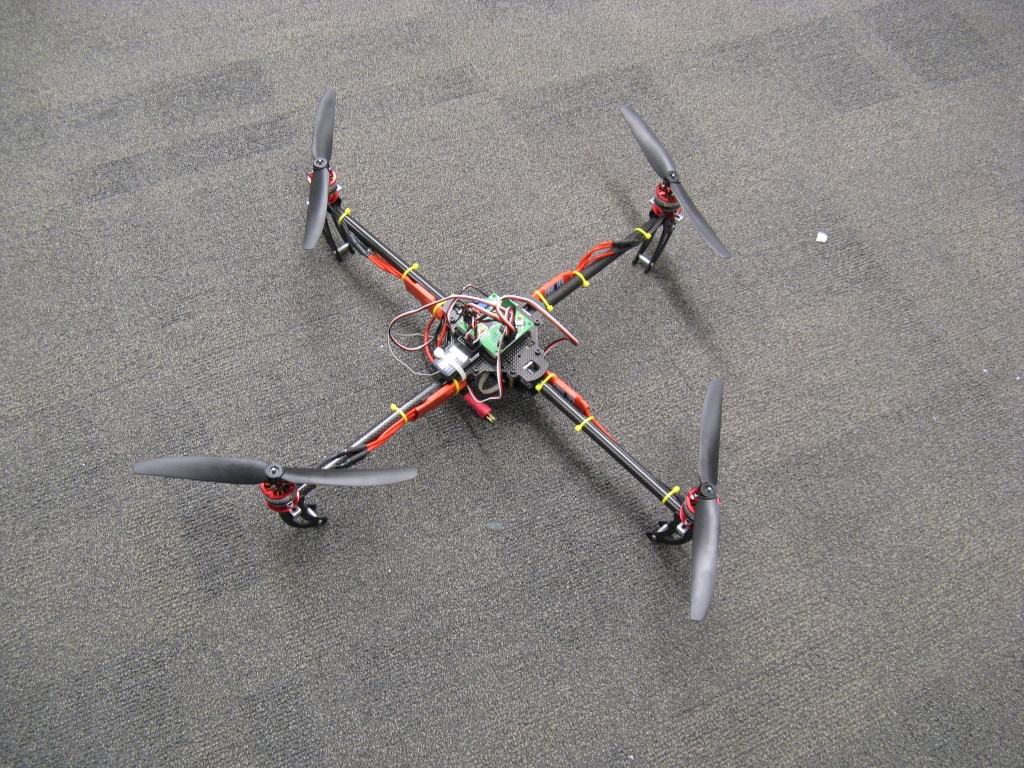
On the suggestion of Max H., I added 1" nylon standoffs to each of the four corners as landing gear:


You might also notice that the motor looks a little different. Although the landing gear does the job of keeping the quadrotor level during takeoff, it also transmits much more of the impact of landing into the motor. (Previously, it was being absorbed by the LiPo battery...) Now, except in the rare soft landing, the impact would dislodge the motor can almost every time. I tried a few different types of adhesive, but they were too brittle and the surface area was too small for them to withstand the shock. In a moment rage-induced inspiration, I found a piece of heat shrink that fit over the motor and cut it so it would just overhang the can when it shrank, which is what you see above. This turned out to be the best idea of the week: after heat shrinking, there have been no further motor can failures.

With the risk certainty of crash landing directly on the LiPo eliminated, I also upgraded to the more potent chemistry of the Turnigy nano-tech line, specifically the 2S, 460mAh, 25-40C pack:

Can it explode just from looking at it?
It's roughly the same size, weight, voltage, and price as the lower-power LiPo I've been testing with, but it has a much lower internal resistance, which means less voltage sag under load. The difference is noticeable, with lower throttle for takeoff and also similar flight time despite the slightly lower capacity, since the motor controllers stay above their low-voltage cutoff longer.

I made one more change which has nothing to do with the quadrotor itself: I decided to take Ryan A.'s advice and fly with a PS2-style gamepad instead of a joystick:

I haven't tried flying with a Weller power supply yet...
It's generally better for controlling robots, so I'm not sure why I expected the joystick to be more appropriate for a quadrotor. The only other quadrotor I've flown used a standard RC flight transmitter, which is closer to a gamepad than a joystick. Thumbs are more precise and faster than entire arms, or even if you're doing it right, wrists. The gamepad has a spring-loaded throttle, which I thought would be problematic. But, with no altitude control anyway, I am always going to be adjusting the throttle even to hover, so it doesn't matter if I have to keep pressure on it. 

Up to now, it sort-of flew, but it would tend to drift around a lot. The series of small changes helped, but I still wasn't really satisfied with stationary hovering. I had speculated that the control loop itself was working and stable, but that the zero angles in pitch and roll were wandering, causing it to sporadically dart off in some direction. With enough space, I could still catch it and bring it back to center, but the immediate goal was to be able to fly it in a small room. For that, a more consistent zero would be necessary. 

To troubleshoot any further, I had to spend some time getting the data acquisition up and running. This should be easy since I've been doing it the same way forever, but for some reason it took me half a day to get the XBee radios to cooperate. And I had to settle for 19200bps transmission because 57600bps seems to be very tricky with XBees, particularly when wireless bootloading is involved. I've had the same problem with the STM32 chip, and I swear I will sit down and actually solve this soon. Anyway, once I had the data running, I did a test run at full throttle with the quadrotor held down on the bench. 

My theory that the power supply was sagging, causing the ADC readings to be offset under load, was quickly disproved and replaced by a new theory:

Specifically, that the sensor signals are total garbage. What you're looking at is a plot of the angular rate signal coming from the +/-300deg/s pitch gyro...while the quadrotor is stationary. So, the noise amplitude is half the full range of the sensor. The complementary filter, which relies heavily on the gyro for computing the angle, is understandably confused, reporting an angle that wanders from -5deg to 11deg, again while the quadrotor is stationary.

And here is where I possibly violate the golden rule of troubleshooting. ("If you can hear it, it's a mechanical problem. If you can smell it, it's an electrical problem. Everything else is a software problem.") I have implemented both hardware and software filters to take out high frequency noise from the inertial sensor signals. But somehow, a massive amount of noise was still making it through. Probing with an oscilloscope revealed it to be broad-spectrum noise, including some low enough to make it through all my filters, with a little bit of an 800Hz sine wave on top of everything. The cause seems obvious now, but I'm so used to electrical noise in high-current motor controllers that I at first neglected to even think about mechanical noise. The test to separate the two was simple:


Running at full throttle with the inertial sensors off-board, the data tell the story:


The rate sensor noise is completely gone, and the angle stays much closer to zero, where it should be. This very clearly points to mechanical vibration as the source of the noise, and more so it suggests that only a mechanical solution will work; the noise is so destructive to the gyro that no amount of hardware or software filtering will take it out. So, having the inertial sensor sitting on headers is no longer an option, and it's time to break out the foam tape:


Attempt #1 used foam-tape only and replaced the headers with a long loop of flexible wire, so as not to transmit vibration through the connections.

Well now that didn't really work at all.
After this failure, I decided to switch over to the C part of the mechanical RC filter by adding some mass to the sensor board:

Sorry, Ryan.
I also made the tape thicker and looser.
The extra mass of the small aluminum plate helps the sensor board establish its own frame of reference that rejects high frequency vibrations that do make it through the tape. And the data:

Hrmmm.
Well, it doesn't look much better, visually. But the noise amplitude is a tiny bit lower and, more importantly, the angle doesn't wander around as much. (The times it does are when I was picking it up and moving it. You can tell because the rate is very clean there.) At least it gives me a little bit of hope that the vibrations can be damped enough to make the signals usable. I decided to give this configuration a chance in flight, using the best controller gains I'd established thus far:


Somewhat surprisingly, the small amount of noise reduction makes a huge difference in flight. (Well, combined with the other changes I made above.) You'll notice that I've changed venues and can actually fly it in this smaller classroom now. It still wanders around a little, but I at least feel much more in control of the wandering. I even manage to land smoothly a couple of times. And the data?


Well, that's basically still noise. Maybe there is more useful information contained in the average rate, but it's still visually lost in the noise. I think more drastic isolation measures, maybe combined with more aggressive filtering, will be required for it to give a clean rate signal. Ideally, it should reject everything above about 100Hz. Since the sensor board mass is still very low, I suspect I will need an even more compliant mount. What the heck is more compliant than loose foam tape?

But anyway, I am happy that its hovering can be contained to a 10'x10' area now...

Wednesday, August 31, 2011

Something Like Flight


After a day of tweaking control loop settings, I've been able to fly 4pcb for at least several seconds at a time before crash landing or hitting a wall. I tried out two different control loop styles, PD control and nested angle/rate control. It's hard to tell from the video which one looks more promising. I want to say the PD control led to longer, more stable flights, but that was also earlier in the day and I was a bit hyper from coffee, so that may have had an effect.

Proportional-Derivative (PD) control would be my first instinct for stabilizing a quadrotor, since it deals directly with the two physical quantities at hand, angle (P), and angular rate (D). Each term gets multiplied by a constant, or gain, and then the sum is sent out as a command to the relevant motors. For pitch angle, the front and rear motors are used. For roll angle, the left and right motors are used. The control structure is straightforward:


The proportional term acts like a virtual spring, pulling the quadrotor back to zero angle (or whatever reference angle the joystick commands). The proportional gain (Kp) is like the spring constant, setting how stiff the virtual spring is. The derivative term acts like damper, resisting motion in either direction. The derivative gain (Kd) sets the damping constant, how viscous the virtual damper is.


With proportional gain only, the quadrotor (which has rotational inertia) will oscillate like a mass on the end of a spring. With derivative gain only, the quadrotor won't know what angle to go to. But with both, it returns to the proper angle and settles there with minimal oscillation. Choosing the exact right gains is often a matter of tweaking. A lot of tweaking.

If there is a net external torque on the quadrotor, for example due to an off-center C.G., it may also be necessary to include an integral control term that ramps up the motor command over time. With this, one motor would spin faster even when the quadrotor is level, canceling out the net external torque. Then the structure would be that of a full PID controller. I've left the integral term out for now.

There's another subtlety: because the motors and props have inertia, they can't instantly spin up to the commanded speed. The sensors, microcontroller, and ESCs also have built-in delay. So, if the gains are too high, the simple model breaks down and the quadrotor will just oscillate. This type of oscillation tends to be faster and twitchier than the proportional-only mass-spring oscillations. So yes, even more tweaking.

After tuning the PD controller for a while, I got a tip from David B. about www.openpilot.org. Now, I'm usually more of a do-it-myself-and-ignore-everyone-else's-version person, but the quadrotor loop tuning guide on openpilot is truly excellent. The video especially is really, really well done. Props (lolpun) to the creator, who can also be seen here demonstrating my ultimate goal for 4pcb, a frisbee launch.

The openpilot control loop uses a different structure, which I would call a nested or inner/outer control loop. The inner loop controls (angular) rate, and the outer loop controls angle. Both the inner and the outer loop contain a proportional (P) and an integral (I) gain, but for simplicity I will leave out the integral term.


What happens in this case is that the angle error gets multiplied by a proportional gain, Kpo, to create a desired rate. The desired rate goes into a second proportional gain, Kpi, to create the motor command. There  integral terms would come in at each step, one in the outer loop and one in the inner loop. Though the documentation suggests using only one of the two possible integral terms. (In the video, both are explained.)

So, I tested this loop structure as well. In both cases, I left out the integral terms and I tweaked the gains until I was satisfied that I was getting the most stable flight I could. The values I get for PD control were Kp:1.2 and Kd:0.4. The units are a bit funky. Starting from degrees or degrees per second, these gains give you a motor command from 0 to 255. So, a 10º error would give a motor command increase of 12/255. A -20º/s error would give a motor command of -8/255. 

For the nested loop, I settled on Kpo:4.0 and Kpi:0.5. Kpi has the same units a Kd from the PD controller. Kpo, though, is now in (deg/s)/deg. Confused? Well then now might be a good time for the plot twist.

They're actually the same thing.


When you ignore the integral terms, anyway, the two different control structures are actually equivalent. Kpi is Kd and the product of Kpi*Kpo is Kp. I didn't know this while I was testing, so the fact that I settled on slightly different gains (0.5 instead of 0.4 for Kpi/Kd and 4.0*0.5=2.0 instead of 1.2 for Kpi*Kpo/Kp) is probably due to the coffee. Interestingly, the gains I settled on are not far from the suggested gains on openpilot, when you convert to their unit scheme.

When you add in the integral terms, though, I think two control structures do have important differences. I couldn't exactly tell you what they are, but it's an interesting thing to think about. Since the main problem I'm seeing now is drift, integral control might be an important part of making it fly better. So that will be one of the things I'll be testing next. Along with that:
  • Landing gear. As suggested by Max H., I'll be trying out some nylon standoffs on the four corners. If nothing else, it will help keep the quadrotor level during takeoff. It also might minimize the motor damage on slight-to-moderate crash landings.

  • x-configuration. I've been using +-configuration, where forward is in line with one of the four appendages of the quadrotor. But when I think of a quadrotor, my mind sees x-configuration, where forward is halfway between two appendages. I don't know why. Also the openpilot video demonstrates x-configuration. The only possible technical advantage I can think of is that all four motors are involved in both pitch and roll, so perhaps any individual motor anomalies will be averaged out more. Or that might just be total BS.

  • Flying with a gamepad instead of a joystick, as suggested by Ryan A. Reaction time and precision may be improved with something more closely resembling a normal RC transmitter.

  • Supply voltage offset correction. I'm not sure if this is actually a problem or not, but the analog-to-digital converter references all signals to the supply voltage. If there is some deviation in the supply voltage under load, the zeros may drift. The gyros have a reference voltage that can be measured to correct for this offset, so I may at least test that voltage to see if its ADC value is varying under load. If it is, I can scale the other signals to compensate.
I would eventually like to be able to fly it in a small room. Whether I get there by tweaking the control or by practice, I don't really care...