Showing posts with label flinch. Show all posts

Monday, January 30, 2012

Did you know that Flinch still exists?

If you don't even know what a Flinch is, I don't blame you, since I last posted about it in June 2011, and it's been sitting on a shelf ever since. It's a miniature Mecanum-wheel robot that was supposed to be a smaller companion to Twitch:


Unfortunately, I ran into trouble with the FingerTech 2.125" Mecanum wheels. The rollers are nicely-molded rubber, but the shafts are just 1/8" brass rods riding directly on the plastic hubs. Steel washers separate the rubber from the face of the plastic, but there is still way too much friction for the rollers to do what they're designed to do. (For reference, here's a smooth-driving ~40lb Mecanum wheel chassis. And here's the full ~110lb robot.)

FingerTech does sell a bearing upgrade kit, but I have my doubts. The bearings they sell are needle roller bearings, which can only handle radial force. The roller shafts can still slide sideways, allowing the metal washers to rub against the plastic face of the wheel. That, if anything, is the large-surface-area friction culprit of these wheels. So, I decided to go my own way and get much more expensive SR144ZZ ball bearings:

Pictured: Lunch money for three days.
Additionally, I bought some 1/8" ID bearing shaft shims, McMaster P/N 99040A316. These tiny shims keep the metal washers that come with the Mecanum wheel rollers separated from the inner race of the bearings, spacing them out from the side face of the wheel. This allows the ball bearings to take up the thrust load, rather than the face of the wheel. Here's the roller, stock washer, and extra shaft shim all in place on one shaft:


The next step was boring out each of the 24 roller shaft holes from 1/8" to 1/4" to accept the new bearings. Since the faces on which these holes are drilled are at 45º to the rotational axis of the wheel, and spaced 60º radially from each other, and there are two different (mirror image) wheels, this was not a simple task.

Or maybe it was, and I made it way more complicated.
In any case, I managed to increase the roller bores to 1/4" in a way that isn't idiotic. The next step in this already-too-long-and-expensive process was to take apart all the wheels:

Sigh...
Then, I pressed in the bearings one by one and...realized I only ordered half as many SR144ZZ's as I needed.

...

FFFFFFFUUUUUUUUUu

...

A few days and $70 later, I finally got around to reassembling all four wheels with the new bearings.


And after all that work I had four wheels that look exactly the same as they did before, but cost 122% more than FingerTech pretends they do. At least they will be more functional. Except they weren't, at first. After just a minute of driving around, half the bearings had slipped sideways, allowing the metal washers to contact the sides of the wheels again. This was mostly because the new bore was exactly 1/4", so the press fits were loose. So, I took all four wheels apart again...

...cursing myself for ever thinking this was a good idea.
And I very carefully added CA to each of the 48 bearings (two per shaft) to hold them in place:


I used a sharp object to spread CA around the bearing perimeter so it would wick into the bore, hopefully without getting into the bearing itself. I managed not to ruin any bearings, but the process took half a day. And then I still had to reassemble all the rollers. 

I wish I could say that the result of all this Mecanum wheel re-engineering was a wonderful drivetrain that will rival Twitch for its speed and maneuverability. I wish I could say it was all worth the effort and the money. But, after putting it all together and running it, it's still only barely passable as a Mecanum, drive:


Yes, it moves sideways. But it's a jerky, bumpy, inefficient sideways. All Mecanum drives are less efficient sideways than they are forward, but this one is really fighting. It tends to rotate while moving sidways as well, which is a sign of mismatched wheel friction and bad weight distribution. That can mostly be compensated out by gyro feedback. But the gyros won't be able to stop it from bouncing around like a cockroach bot. That's mostly a function of the wheel shape and twitchy nature of small/light robots with oversized motors.

So I'm not sure how much more time or money I'm willing to spend on it. I feel like adding weight, switching to a higher gear reduction, and adding closed-loop rotation control would help a lot. But the thought of buying new gearboxes, a gyro, and possibly stiffer chassis plates makes me cringe. I'm glad it isn't just sitting half-finished on a shelf anymore, though.

Thursday, June 16, 2011

Pan-Project Update 6/16/11

I got a little distracted last weekend...

...by F1 cars.
I took a spontaneous trip to the F1 Canada Grand Prix, the only F1 race held in North America. It turned out to be a very rainy weekend, but even so the F1 cars were impressively fast and loud:


It's literally not possible to capture the sound of an F1 car passing 15 feet in front of you with my camera. The microphone just saturates and it just sounds like an explosion. Then again, that's sort-of what it sounds like in real life too, when your eardrum saturates. Combine the sound with the ominous sprays of water shooting 20 feet above the treeline on the far side of the track and it's like something out of a monster movie: You know it's coming for you next. Max has a more thorough summary of the experience, plus some better video.

But since we ran into car trouble (lol) on the way back from Montreal, I've had to spend a few days catching up with work. I made a bit of progress on some projects before and after the weekend, but not enough to justify an entire post for any individual one. So, I will do the thing I hate doing and make a Pan-Project Update to make excuses for highlight the lack of  progress on each.

First and easiest,


Sensorless Field-Oriented Control

I've made no progress on this. I have a decent idea of how to start, and I maintain my opinion that you can do pretty much anything in software if you spend enough time messing with it. Some day soon I will do it, and nobody will care because it's software and has no tangible meaning, but then I'll just laugh at everyone.

Moving on then,


Flinch

I got the M3 screws I needed to finish mounting Flinch's four gearmotors, so I did that:


Flinch is a straightforward 4WD robot layout, so there were no surprises here. It's essentially the same size and shape as mini4WDbot:


In fact, as a starting point I just transfered mini4WDbot's entire electrical system over to Flinch. That includes four repurposed VS-11 servo drivers, an Arduino Nano Carrier, and a 7.4V LiPo. I wanted to test the open-loop performance of the FingerTech mini-Mecanum wheels before investing significant effort into the inertial sensors for high-speed Mecanum-ing.

Unfortunately the low-speed tests didn't work out so well. I've worked with larger Mecanum wheels before and even those are very sensitive to weight distribution, driving surface, and the condition of the rollers. The rollers on these wheels are rubber with brass axles riding in plastic wheel hubs. Off the ground, they roll just fine. But under axial loading, the steel washer spacing the rubber roller out from the wheel does not make a very good thrust bearing. Maybe with a lot of tweaking they might do something Mecanum-like, but I don't have the patience for that.

Plan B involves putting real rolling-contact bearings on each roller axle. FingerTech sells these (an implicit admission that the regular axles leave something to be desired?), but they're needle bearings, which won't help much with friction between axial-contact surfaces. So I instead opted for SR144ZZ tiny ball bearings. At least with these I can use tiny shaft spacers to keep the washer from making contact with the side of the wheel. Of course, this means carefully drilling out each roller axle and pressing/gluing in a tiny bearing. After that, another open-loop test to evaluate the new level of Mecanumosity.

Next,


DirectDrive

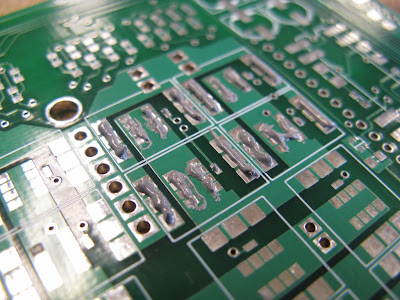
I'm starting work on my larger motor controller, called DirectDrive because it uses a crapload of DirectFETs. I ordered a single board for testing, since usually my v1.0 motor controllers wind up failing spectacularly in some way anyway. But I can still be hopeful, right? Plus, I get to play with a new toy:


Add it to the list of things that are absurdly cheap if you buy them from China, a bagel toaster programmable reflow oven. DirectFETs cannot be soldered with an iron, since the gate and source pads are under the device. I was planning to use a hot air station, but this is way faster and I've never done it before so it was an opportunity to learn. It's pretty simple:

Step 1: Apply paste haphazardly without a stencil.
Step 2: Place MOSFETs in the correct orientation.
Step 3: Toast for 7 minutes or until lightly browned.
Actually there are a few little DirectFET-specific tricks I learned along the way that I would definitely use in the future:
  1. DirectFETs are ever so slightly magnetic. This is great because you can pick them up with a small neodymium magnet (instead of tweezers) and carefully lower them onto the paste. Once they touch the paste, surface adhesion is enough to pull them off the magnet.

  2. You can look at the board edge-on to verify that there is still a gap between the gate and the nearest row of source pads. If not, you probably want to clean off that one and try placing it again. After reflow, this gap is usually still visible. I did see a few after reflow where the gap was no longer visible. But upon measurement, they did not appear to be shorted.

  3. The drain tabs and source pads need a lot of paste. Screw stencils.You can lay down a thick line. It's got to conduct a lot of current anyway, and much of the volume of the paste is flux, so it gets thinner as it evaporates. It's not like a BGA IC where you have to worry about shorting adjacent balls. There is only one critical point (between the gate and source) and by preferentially steering the line of solder paste toward the far side of the source pads, you can avoid bridging that.

  4. You can and should test the MOSFETs after they have been reflowed. I test to make sure there are no shorts from gate to drain or gate to source. (If you shorted drain to source, you did something terribly wrong.) I also check the capacitance from gate to source, which should be near the datasheet spec and consistent across all FETs. And finally I check the on-state resistance.

As far as alignment goes, some of the FETs are visibly rotated by a few degrees. However, they are very flat, something I was concerned about for heat sinking. I'm happy with the procedure and will be even more confident in recommending it after I load test this board.

One minor problem was that the ACNW-3190 gate drivers that I was so excited about last post turned out to be 400mil DIP packages instead of 300mil. I should have RTFDS more carefully. Anyway, that means I will have to go back to the 2.5A HCPL-3120 drivers. Though maybe I can, you know, stack them on top of each other or something.
And finally,


???

The mysterious four-wheeled Edgerton Center Summer Engineering Workshop 2011 project. It's not quite ready for a reveal yet, but here's a teaser:

Saturday, May 28, 2011

IRL Flinch

What was I working on?

Oh, right, it's summer, the most productive build season by far. No more excuses: Quals are done, I didn't fail out of MIT, and it's time to get back on track with the current list of open and pending projects:
  1. Flinch, a miniature Mecanum-drive robot, the subject of this post.
  2. Adapting the 3ph v3.1 controller for sensorless field-oriented control. Mostly a software project.
  3. A new brushless controller with a lot more power and several new tricks I've been meaning to try. The first iteration is almost ready for circuit boards. Look for a post on this shortly. Hint: It's called DirectDrive.
  4. The newest vehicle from the Edgerton Center Summer Engineering Workshop (of DIY SegwayCap Kart, and BWD Scooter fame). This one is very cool. Hint: We're back to four wheels.
But first, Flinch. Here's a reminder of where this one is going:


Like Twitch, Flinch is an omni-directional, or "holonomic", robot. It doesn't have Twitch's fancy linkage steering, though. Instead it uses Mecanum wheels to accomplish 4I3O omni-directional control. I suspect it will take a good amount of software help to make the tiny Mecanum wheels effective at the kinds of speeds I hope to achieve with Flinch (~10fps), but for now I'm focusing on getting the mechanics and temporary electrical system in place.


The first order of business was to produce the motor mounts. I made all four at once from a piece of 1" wide aluminum stock, cutting them down to size later:

Under normal circumstances, 16 blind-tapped 4-40 mounting holes would be an annoyance, but compared to Quals, it was a relative pleasure.

Next, I made an insta-chassis with top, bottom, and side plates:


The top and bottom plates are laser-cut UHMW from Big Blue Saw. (I guess in this case it's more like Big Infrared Saw since it was probably cut with a CO2 laser...) I've never worked with UHMW before, but it seems to be a nice, cheap alternative for robots that don't quite justify an aluminum plate chassis. To make up for the bendiness of the plastic top and bottom, I ditched the standoffs in the original CAD model for solid 1/4" side plates.


I did put the standoffs to good use, though: From the side plates, a standoff sticks into a bearing I added to the outside of each Mecanum wheel, acting as a dead axle. It provides a bit of extra support to the wheel, even though the structural loop around the chassis is not as stiff as it would be with aluminum top and bottom plates. After dropping it a few times (on purpose), I found that the bearings would just pop out, so I added some washers to hold them in place:


I'm missing some M3 screws required to mount the motors, which is preventing final assembly for now, but here's what it looks like all together:

There's something wrong with this picture. If you can spot it, you win a cookie.
After I get the motors mounted, I may borrow the electronics package from mini4WDbot to do some initial testing. I don't expect very good open-loop performance, especially at high speeds, but you never know. I might be pleasantly surprised by the handling. And even if not, it's a good way to make sure all the motors work and the wheels do roughly what Mecanum wheels are supposed to do.

Wednesday, May 11, 2011

Meet Flinch


Every year during and immediately after 2.007, I have a bit of robot nostalgia. Last year, this resulted in Twitch, Jr., a switched-mode omnidirectional robot named after Team 1565's '08 FIRST bot. Since then Twitch has had a professional HD camera mounted to it, driven a microphone stand around at the 2.007 final contest, been on something like three Japanese TV shows, and recently been to the Cambridge Mini Maker Faire. It's by far the most fun robot to drive, ever. And I've driven a lot of robots.

But now I think it's time for Twitch to have a friend:

d'awwwww
Flinch is a smaller robot, 9"x8"x2.125" and probably less than 3lbs. While Twitch uses a fairly rare linkage drive, Flinch will feature the somewhat more common Mecanum wheel solution for omnidirectional motion. Mecanum wheels have been around for a while, but were popularized by FIRST and AndyMark over the past seven years or so. You can see what exactly they do on Team 97's '08 FIRST bot. (2008 was a great year for drivetrains.)


The wheels give it the ability to defy typical 4WD robot kinematics by controllably moving sideways. Two axes of translation and one of rotation are simultaneously available, making it a true holonomic drive. (Twitch, in its most extreme configurations, only has two degrees of freedom.) What makes this possible are angled rollers on the Mecanum wheels:


Flinch will use four of these 2.125"-diameter Mecanum wheels from FingerTech. They each have six rollers angled at 45º from the drive axis. Effectively, a robot with four of these wheels, independently driven, can create force vectors at 45º angles from each wheel's contact point. By summing these vectors, the translation and rotation of the robot is determined. Or, if you know the (x,y,θ) you want, you can run them through a 4x3 matrix to recover the wheel commands. (I guess the extra degree of freedom is the burnout axis.)

Straightforward kinematics will only get you so far, though. The real difference between a mediocre Mecanum drive and a good Mecanum drive is closed-loop control. The addition of a gyro to control the rotational degree of freedom made a big difference in Twitch's driveability, and I suspect at least that much will also be required for Flinch. I left a standard mounting pattern for electronics so that I can start with an Arduino Nano Carrier (shut up) and upgrade later to a full custom solution with integrated inertial sensors, motor control, and maybe even a magnetometer for Earth-oriented control. More on that in a later post.

For now, I've mostly been focusing on the mechanical elements. For one, an obsessively detailed CAD model of the wheel. I don't think I've ever been so disoriented by reference geometry before.


And then there are the rollers. I know there is a parametric equation governing the profile of the rollers, and there seems to be some discussion as to whether it is parabolic or elliptical. I took the easy way out:

It is what it is.
Next, motors. Unfortunately, Banebots has entirely stopped making small gearboxes, apparently. Every single one is out of stock. They've also folded up the 36mm RS-380 line that Twitch utilized so well. So basically, they only sell P60 and P80's now? And even those take 10-15 business days to ship? Fuck you, BaneBots. (I'll probably still buy your shit since it's cheaper than any alternative.)

Also, I refuse to use FingerTech's 16mm gearmotor (the one for which this wheel was designed). It just looks so dinky. The FK-050 motor and the flimsy-looking shaft are not my style. Aren't there any companies still making good robot drive solutions!? Oh yes...Pololu Robotics, where I got the motor controllers for both Twitch and Segstick. They have their own line of gearmotors now, too. And they actually don't look dinky.

Metal.
Flinch will use the 9.7:1 HP model, probably running 7.4-11.1V like Twitch. This would give it a no-load speed of around 10fps, even accounting for the √2 from the Mecanum wheels, and significantly more than its own weight in available traction force. Of course, this all depends on having two things: (1) a fast and powerful ESC, which I suspect will have to be custom, and (2) very good closed-loop control to keep it stable at high speeds. If I can meet those two criteria, I think Flinch will be amazingly quick.

Flinch will also be a little more durable than Twitch. By necessity, Twitch has outboard wheels, but this puts them in a vulnerable location. They also have wimpy plastic spokes that tend to crack when Twitch hits a wall, or when other robots attack Twitch for no reason. Since the Mecnaum set is a rather large investment, Flinch will instead have enclosed wheels, and they will be doubly-supported:


The addition of a tiny 1/4"-ID, 1/2"-OD bearing is easy, since the wheel bore is already just under 1/2". And the outboard axle is the same 1" standoff used to space out the two chassis plates. Simple. Nevermind that the chassis itself, with wheel wells cut out, is probably not rigid enough to make the structural loop meaningful. At least the wheel will look like it's supported on both sides. It's probably slightly better than nothing.

The chassis plates will be waterjet-cut, so the only real fabrication required are the motor mounts and outboard axle mounts. So basically, I could have a laser-cut prototype done some time this week...

...because clearly Designing and Manufacturing a robot with interesting System Dynamics and Controls is the best way to study for quals.