Showing posts with label kart. Show all posts

Sunday, August 22, 2010

Cap Kart: Shakedown

First, some new test drive video:


As good as that looks, it did not come easy. In the last test drive, the kart suffered a MOSFET failure after just a few runs. For those unfamiliar with power electronics and motor control, the MOSFETs (or IGBTs in higher voltage controllers) are the primary elements that control how much current gets sent to the electric motor. A good analogy in an internal combustion engine might be the throttle body. When they fail, it's usually the end of driving.

IXYS VMM 1500-0075P: Possibly the largest MOSFET you can actually buy.

Tracing through the data from the last test drive shows the MOSFET failure clearly enough, but only offers hints about the cause. My best guess was that the 12V supply was insufficient for the gate drive optocouplers (Avago HCPL-3120) that turn the MOSFETs on and off. They're really designed for 15V supplies, and the combination of a smaller 12V battery and a higher gate charge requirement on the large MOSFETs may have tipped them just over the edge. If they shut down permanently, the kart should just coast, but if they shut down and come back on after a brief interval, the MOSFETs may see a quick burst of current since the controller feedback loop had been broken and it needs to "find itself." Should this destroy the FETs? Probably not. Did it? I don't know.

In any case, the data and some bench experiments confirmed the presence of some current spikes when running the gate drive on 12V. Switching to 15V eliminated these spikes. Since the gate drive runs off its own battery anyway (for noise immunity), it was an easy matter to change to a small 4S lithium polymer battery, at 14.8V nominal. In a moment of pure overkill, the battery of choice is now a 1.8Ah Turnigy Nano-Tech. Yes, a batttery that could potentially supply 45-90A, powering the 0.5A gate drive and logic circuit on the kart. Where did I put those fuses?

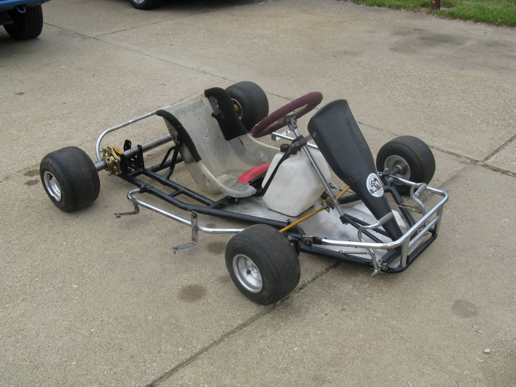
Electrical problems out of the way, it was clearly time to move on to some sort of mechanical failure. And the most obvious place for that would be in the brand new rear axle differential.

Why can't it be this easy?!

After the first test drive, we noticed that one of the snap rings holding the gears on their respective shafts in the differential had popped off and was nowhere to be found. The entire case had also shifted a good quarter-inch. Rather than admit the obvious - that some unconstrained axial forces knocked the snap ring off - we chose to assign questionable blame to things like loose set screws and misaligned chain. Well, the following week we made it as far as the elevator before the snap ring popped off again.

The full extent of last week's test drive.

So, we took it back up the elevator, cried for a while, then decided that what was really needed was a better way to constrain the differential axially. After a few hours of trying to avoid taking the whole differential off the kart, we wound up taking the whole differential off the kart. And by that point, the easiest solution was just to add spacers to the shafts that fix the distance between the outer and inner bearings, as shown in this top view:


The outer bearings are already well-constrained by the shelf that we built around the rear axle. The new spacers, in red, fix the differential in place axially. As an added bonus, one side's spacer accurately sets the gap for the brake disk. This fix took us an entire day, and since we can really only test drive on the weekends, it basically meant one fewer test drive this summer. Bummed as we were, the fix was important. There is no acceptable outcome if the gears fall out of the differential.

Back to present day. If you're keeping track, we're due for an electrical failure now.

The goals for this test drive was to abuse/test the rear axle a bit on our slalom course, and to see if the change to a 15V gate drive supply would save the MOSFETs. The first goal was met unquestionably. No snap rings fell off and the differential seemed perfectly happy the entire time. Congats, Max. The slalom, which was pretty damn near impossible in 2008, is now too easy with the lighter kart and differential. The only real mechanical issue left to deal with on the kart is the somewhat squishy brakes.

Back to the controller. One of the untested bits of the new software was the Costas Variable Transmission that does constant-power field weakening on the separately-excited DC motor. I decided I would just go for it:


You can see me flooring it, the armature PWM maxing out, then the field PWM dropping to almost nil as the kart continues to speed up. The armature current holds at a pretty constant 250A and the battery voltage is right at the 30V cutoff. This seems to work exactly as designed. Upon releasing the pedal, the field PWM first increases, then the arm-- ugh not again. Almost as soon as the current goes negative, bad things happen. Zooming in on the one-second interval around the fault:


Here I've highlighted three interesting intervals. In interval 1, the huge negative current spike (-560A) is detected. It would be easy to blame such a spike on bad regen control tuning, but if that were the case, the power would be going back onto the battery and the DC bus voltage would skyrocket. Instead, it does the opposite, dipping to 15V and then even 10V. To me, this suggests that a ton of power is coming out of the motor and out of the batteries at the same time. And there's really only one place for that power to be going...straight into the MOSFETs...

Luckily, the new fault detection software picks up the problem almost instantly and shuts down the drive. (Thus, it has twice prevented further destruction.) The hard faults cause the PWM drivers to shut down immediately, which is why the armature and field commands drop to zero. Interval 2 is the time between the drive turning off and the contactor opening. (Some time is given to allow inductive energy to be dissipated.) Unfortunately, by this point, the MOSFETs are totally dead. It's clear that current is still going into the motor and coming out of the batteries, even with no drive command. This actually shows up as a brief burst of acceleration, since the controller is no longer capable of throttling the current. The contactor opens between interval 2 and 3, less than a half second after the fault, at which point the bus voltage starts draining through whatever horrible new low-resistance paths have been created in the MOSFETs.

All this happened while I was happily driving along. I didn't realize there had even been a fault until I came to a stop and noticed the DC bus voltage was reading 5V. At least the new software is way smarter than I am. At this point, screw electronics. Seriously. I don't know what the failure mechanism was and the data stream does not show anything that would indicate a cause, only effects. The only thing significantly different about this controller than the one that ran the kart in 2008 are the IXYS FETs. From an experimental troubleshooting point of view, replacing these was the next best target.

Enter MetalFET.

After the previous MOSFET failure, I decided to enact a Plan B since we have only a limited number of IXYS MOSFET replacements. Plan B was a custom-designed circuit board that is more copper than not. And I'm not talking ground planes. I'm talking a serious current-carrying copper bus bar and FR4 sandwich, hence the metal part of MetalFET. Oh yeah, and the FET part...tiny MOSFETs. Tiny only in size, though. These are seven-legged IRFS3107 HEXFETs, the most badass MOSFETs in existence as far as I'm concerned. 

Sorry IXYS, stealing your critical dimensions.

The board and associated aluminum/brass hardware adapts these tiny FETs to the same form factor as the IXYS MOSFET brick, facilitating drop-in replacement. The kart formerly ran on the through-hole version of these IR FETs, four in parallel for 300A. But they were mounted to bus bars that doubled as heat sinks. To get a similar thermal performance for these surface mount FETs, I used unmasked boards and screwed 1/4" aluminum heat transfer blocks to the drain planes of both sides:


The truth, though, is that I really did not want to use these. The IXYS FETs are a much nicer, more professional-looking solution. These are a hack I came up with in a few hours of work (plus three days of waiting for circuit boards). The Cap Kart knows just exactly how to push me to the limits of my patience, hence the original post title. So with really very little time left of summer test driving, we swapped to an untested, locally-grown MOSFET module.

Something traumatizing about the first Cap Kart test drives must have still been in the back of my head, because a few weeks ago I went to Radio Shack to replace the 350W inverter I bought back in 2008 and subsequently lost. Pretty much the only reason I would ever need a 350W inverter would be for field soldering off a 12V battery, and pretty much the only reason I would ever need to do that would be to fix the Cap Kart. And as luck (or lack thereof) would have it, I was able to put it to good use, if only once, to move the gate drive wires over to the untested MetalFET.

Yes, the homemade MOSFET module is now zip-tied to the shelf.

Honestly, I would have given this less than 50/50 odds of working, especially since it was completely untested. But, as luck would have it, it works totally fine. All of the test drive video above was run on the MetalFET. At times it was a bit warm...not hot, just a bit warm... So there you have it - a $30 hack that works where the $300 MOSFET modules fail. Go figure.

That nightmare out of the way, time for some more fun. Here's a run that uses the "three speed manual" mode:


You can see the system traverse peak power three times, with the estimated motor output power (P_Vemf) holding steady at around 5-6kW. While the Costas Variable Transmission mode will do this smoothly and automatically, the goal of three speed mode is to actually feel the gear change "kick" as the field voltage is varied in steps.

And here's one more battery I-V curve:


This is the widest one yet, covering -75A to 300A. The battery internal resistance (V/I slope) remains constant over that whole range. They may not be the most powerful batteries, but the Thundersky cells are remarkably consistent.

The Cap Kart: Overinstrumented? Yes. Of questionable power electronic legitimacy? Yes. But a lot of fun to drive.

Thursday, August 5, 2010

TS-LFP40AHA In-System Data

As part of the Cap Kart Summer 2010 upgrade, we switched from 79Ah @ 36V lead-acid batteries to 40Ah @ 39.6V lithium iron phosphate batteries (Thundersky TS-LFP40AHA). The old batteries weighed 159lbs. The new ones weigh 42lbs. We got them from Elite Power Solutions, and they even came with little carrying handles:

One of three 13.2V modules.

The loss in capacity is somewhat overstated since lead acid batteries are rated at fractional C rates, while the lithium ion batteries are rated at 1C. They also came with balancing boards, but they don't even fit on the cells. (The drain FETs don't clear the vent caps without additional washers to space them out vertically from the terminals.) Not worth the extra $100. Get yourself one of these instead for $13. They don't balance the cells for you, but they do have an audible alarm for over and under voltage, so you know to stop driving or stop charging and balance if necessary.

I was a little worried about the power-handling capability of these cells, since they are only rated for 3C continuous discharge (120A). The kart at full tilt sends 300A to the motor. I wasn't expecting 300A from the cells (except at high speeds, the motor current is higher than the battery current), but something around 5C or higher for peak discharge would be nice. The internet is fairly bad at documenting the capability of these cells. The closest thing to consensus I found was a per-cell resistance of about 3.5mΩ. Assuming a low-voltage cutoff of 2.5V and an open-circuit voltage of 3.3V, that gives a peak current of (3.3V-2.5V)/0.0035Ω = 229A, and a peak power of 2.5V*229A = 573W. With 12 cells, that's almost 7kW, which would be just about right for the kart.

Enough math. Here's some on-kart test data:


This is for the full 12S battery pack and includes the resistance of the bus bars, fuse, wiring, manual switch, and contactor. It's at about 75% SOC and shows both charge (regen) and discharge data. The output is very linear, which I guess makes sense for a cell with relative high DC resistance. The resistance per cell came out to about 3mΩ and it has no trouble putting out 6kW, with still a bit of room before the low voltage cutoff (30V for a 12S pack). In other words, works as advertised by the internet or slightly better. For the price, hard to beat these cells. But don't expect to win a drag race against A123s.

If nothing explodes, there should be new kart test drive video soon!

Tuesday, August 3, 2010

Cap Kart Summer Rebuild 4

The Cap Kart runs again, field driver curse notwithstanding.

First, the mechanics. We just needed to mount the freshly-cut rear axle to the outputs of the brand new differential. Except how do you connect a 34mm I.D. hollow axle to a 1-1/4" (31.75mm) keyed shaft?

Step 1: Fill the gap with a flimsy-looking aluminum sleeve.

Step 2: Fill the keyway with flimsly looking 8-32 small pattern hex nuts.

Step 3: Fill the nuts with flimsy-looking 8-32 brass-tipped set screws.

The only good thing I can say about this is that it doesn't do what you think it does. The 8-32 screws are not in shear; they're in compression, pushing up on the nut and down on the shaft, such that at least some of the torque is transmitted through friction interfaces and there isn't any backlash. I don't know if that makes me feel any better about it, since couplers for this size shaft tend to be much beefier looking. But this costs nothing, weighs nothing, and might work. My horrible standard for judging this is that the traction-limited rear wheel torque is something like 100ft-lbf. And I would totally hang off a 1-foot bar attached to this...

...Moving on to software.

Is that a game?

We finally got to load the code. Costas wrote the State Machine of Doom to handle the multi-mode electronic transmission, as well as a whole new set of fault codes that I wish we had back in 2008 when we were regularly blowing up motor controllers. The kart transmits 13 bytes of diagnostics back to a waiting laptop at 20Hz, including one byte of potential faults ranging from "hard faults" such as loss of accelerator signal to "soft faults" like battery power limiting. If anything goes terribly wrong with the controller, the data logger is like the black box.

Even if things go right, the data is still useful for performance analysis. For example, testing the effective resistance of our brand new 40Ah Thunder Sky batteries.


What you see there is actual kart data recorded during a bench test. Battery current is the same as motor current, in this case, because it was run up to 100% PWM and full throttle before engaging the load (i.e. the brakes). Since the motor controller measures motor current and battery voltage, it was a simple matter to cross-plot them to find the effective resistance of the pack. A 6V sag at 150A gives a pack resistance of about 40mΩ, or a per-cell resistance of about 3.3mΩ, right on target. That means an effective peak power of about 7kW from the 12S battery pack (taking 2.5V per cell as a soft limit), the majority of which goes to the ground (we hope). Add in an extra 3kW of on-demand capacitor boost and you get reasonable power out of just 50lbs of energy storage.

That all seems very easy, but if Summer 2008 was any indication, there is no way it all just works. And if one part were to break, I know exactly which one it would be. So continues the curse of the field controller.

Now, there's no real technical challenge to the field controller. It's not like the monster 300A synchronous half-bridge that drives the armature. It's a 10-15A drive into a load that looks like a 1.3Ω resistor and a giant inductor. The current in sets the field strength of the SepEx motor, which in turn sets the torque-speed curve.

But the problem isn't ever a technical one. Curses don't work that way. For example, one time, the reversing switch welded itself shut, taking out the rest of the controller when it was switched back to forward, shorting the battery through the field-drive FETs. This time, the curse first manifested itself in the form of some really shady-looking gate drive waveforms:


That turned out to be a simple problem to fix; it was only on the high-side drive which led me to the conclusion that it just needed a bit more bootstrap capacitor and a bit less pull-down resistor. But it still made this annoying crackling sound at high loads. In fact, it's very similar to the crackling sound I've heard before and always attributed to the switching regulators on my controllers. Except this controller doesn't have any switching regulators... I decided to investigate more. And by investigate, I mean destroy the entire field controller.


This is what happens when you use two of the same color alligator clips. Inevitably, you clip the two load leads together and the two outputs together. This short-circuit immediately vaporized a trace on the circuit board...


...which in some cases would be fine. But this time the resulting voltage spike took out 3 out of 4 MOSFETs and both gate drivers. Are you starting to see what I mean by the curse?

Anyway, with a new set of MOSFETs and gate drivers, plus a little help from real electrical engineers, I finally tracked down the source of the crackling to over-aggressive gate drive. The turn-on waveform would occasionally ring or go unstable. Turns out in some instances it actually helps to slow down the gate drive a tiny bit to regain stability. Kinda defies my whole understanding of gate drive, which to this point had been "go as fast and as hard as possible." It makes me wonder if I can go back to my old controllers and fix the crackling the same way...

But for now, everything could finally go back together for a spin-up of the brand new rear axle:

Wednesday, July 21, 2010

Cap Kart Summer Rebuild 3


In the previous post, we crossed the state of maximum entropy, having taken apart basically the entire rear of the kart and all the wiring. I'm happy to report that things are now being put back together, starting with the shiny new rear axle differential, which is pictured above (some assembly required). By virtue of bad machining good design, the precision shafts press tightly into one side of the case, but are a free fit in the other, so assembly is actually fairly easy. The finished product:


Savor the shiny multi-tone metallic look, because next time you see this it will probably be an indistinguishable cylinder of black grease. We were happy to see that it does in fact function as a differential should, even with all the screws tightened. It won't be the smoothest, straightest, or quietest differential in the world, but guess what, we made it and it works. Props to Charles for the simple concept and Max for the execution.

We had a few options for mounting the differential to the kart. There are two steel frame tubes under the rear axle that at first seemed like a prime target for welding on new bearing mounts. Upon further inspection, though, the rearmost of the two was attached to chassis ground structure with cracked aluminum clamps. So, we chose instead to mount everything to the aluminum shelf above the rear axle using our best friend, 80/20 t-slot extrusion. First, we got some of the nicest waterjet parts I have ever seen from Big Blue Saw's low-taper waterjet:

No joke, that's how they came out of the box.

 The boring part: finish-machining the bearing holes.

Angry brake caliper mount.

A new bag of t-nuts and some finicky alignment later, and we have a mounted rear differential:


All that's left to do, mechanically, is cut the rear axle and reattach the two halves to the outputs of the differential. The proposed method of attachment (34mm ID hollow shaft to 1-1/4" solid keyed shaft) involves thin-walled aluminum sleeves, 8-32 screws and small pattern nuts, and hot glue. I'll leave it at that.

The controller and new wiring have successfully survived power-up, so nothing is wired up backwards. We're taking the approach of writing the new software in its entirety without testing it piece by piece. It will just work on the first try. For my part, I became obsessed with having a flashy telemetry display after I watched the Solar Impulse videos. (Is it sad that after watching video of a solar plane, I decide the thing I want to do is write new telemetry software?) Anyway, I upgraded the existing telemetry system to have a scrolling plot:


Left-clicking on any variable sets it to the blue scope trace. Right-clicking sets it to the yellow trace. The telemetry is also recorded for later analysis and can be synced to video. In other words, we just might have the most over-instrumented go-kart in the world.

And yes, I created a GUI interface using Visual Basic. See if I can track a go-kart.

Next: movement.

Tuesday, July 6, 2010

Cap Kart Summer Rebuild 2


Actually, that tiny little 2.2μF capacitor is of critical importance. It supplies the gate drivers, which are specialized chips that turn on and off the high-power transistors (MOSFETs) in the Cap Kart controller. They were formerly 1μF capacitors, but these new monster FETs have a gate capacitance of 0.25μF. So it's like if you have a bucket of water and a small garden hose to fill it and...well there's another taller, skinnier bucket and..... I don't know. It just needs more capacitance, okay?

And even with more buffer capacitance and smaller (5Ω) gate resistors, it still takes an eternity (i.e. two microseconds) to turn on and off these behemoths:

You can do it! Can you?

 It's not the world's snappiest gate drive, but the passive shoot-through protection integral to this half-bridge design is working. You can tell  by the delay between one gate turning off and the next one turning on. All that's left is some color-coordinated wiring:

Each gate gets a local pull-down resistor and 16V Zener diode for protection.

And the controller is pretty much ready to go:


Well, the hardware part anyway. The part that didn't change. As for the new control software...

What the...?

It's complicated. Or maybe it's simple. Either way, it's progressing. The goal is to implement constant-power field weakening on the SepEx motor. Before, we used fixed "gears" and a manual shifter to set the field strength. This is fun, but not as clean as a constant-power field weakening setup.

On the mechanical front, we've finally passed the state of maximum entropy and started putting things back on the kart. The battery trays were cut down to accommodate the smaller lithium-ion battery packs...

...which look damn good.

As it turns out, we have room for four more cells if we decide we need them. But for now we will be running 12S (39.6V nominal). This is a bit higher than the 36V nominal lead-acid setup, but it will be more than offset by a higher internal resistance per cell (more voltage draw-down). That's where an extra 12V from the capacitor may come in handy.

To accommodate the new motor orientation, a slot for the chain had to be added to the All-Purpose Mounting Shelf. (Seriously, everything we've added to the kart except battery trays mounts to this one quarter-inch plate.) This operation involved a bit of 80/20 mill fixture trickery.


The chain will pass down through the shelf to the custom-built axial differential. Speaking of which:


One side of DiffMaster Max's baby is done. The main radial bearing pressed cleanly into the side plate (on the side not visible). A thrust bearing (McMaster PN 5909K38) sits between the large output gear and the side plate. A spring clip holds the large gear in place on the output shaft. The four precision-ground gear shafts (three pictured) are to be screwed in from both sides. Two more shafts will provide structural support. Here's a video of the half-diff. Next: finish the second side plate, add spacers, and final assembly into the rear axle.

 Coming soon to a parking lot near you.

Monday, June 28, 2010

Cap Kart Summer Rebuild 1

The Cap Kart rebuild has begun in earnest, so I'll try to post semi-frequent updates on the progress. It's a summer-long project, hopefully culminating in some new test drive video and data by August. The static website will eventually be updated as well.

First, the kart diff. This is a real mechanical test for us. In 2008 we chose to invest in an engine-less racing kart specifically so that we would not have to mess with any critical chassis or drive mechanics, short of adding a chain and sprocket for the electric drive motor. Now we're essentially tearing apart the rear axle to add a custom-built axial differential. It's a lot of heavy-duty steel fabrication...

Serious Business.

 ...for a group that's used to designing aluminum parts to be cut on an abrasive waterjet and carefully assembled. But rest assured we can bring some of our skills to bear on the project. Namely, making it look good.

Photo-render courtesy of DiffMaster Max H.

Now might be a good time to explain how it works. Like a more conventional bevel gear differential, the axial differential allows a single input (the chain drive) to supply torque to both rear wheels, while still allowing them to rotate at different speeds. This is most obviously necessary when turning, since the outside wheels must travel faster than the inside wheels. An "open" differential like this follows a simple rule: the torque on each wheel must be the same.

Formula SAE cars often use a chain-drive differential (though probably not axial) on the rear axle. In fact I'm sitting right next to one so why don't I take a picture?

 See it?

It's inside that aluminum can.

It's not obvious from the picture, but the brake disk and sprocket are both fixed with respect to the differential case. This way, braking torque is applied at the input and split to the rear wheels in the same manner as accelerating torque. We'll be pursuing a similar design in ours, mounting the brake disk to the hub opposite the new sprocket.

It will be fun to assemble. For now, though, it's just lots and lots of fabrication:

 Gear stock is cut to length, then bored out.

Hubs are formed out of aluminum disks. 
 
Ready to add holes for the gear posts.

Nearly completed hub.

And the gears actually do mesh...so far.

 While the mechanical side is progressing, I've been trying to remember how exactly the controller works. (I mean, conceptually I remember what it does, but the details of the wiring have been lost a little bit to time.) While we're rebuilding and adding new lithium-ion batteries, the plan is to update the power electronics as well. The only substantive change, though, will be replacing the contactor/diode switching circuit that enabled the ultracapacitor boost and brake modes with semiconductor switches. Here's what I mean:

If you're looking at this schematic and thinking "WTF?" then you're in good company. It took us some time and some trial-and-error to settle on this particular method of using the Maxwell ultracapacitor module, and even longer to recognize that it actually does have some significant advantages over other methods. All that is part of Cap Kart v1 development history, though, so I won't focus on it here. If you stare at the circuit for long enough, it might make sense.

The only change is that where there was a contactor and diode before, there is now a second high-power half-bridge. This bridge will only be used to turn the capacitor boost on and off, but in theory it could also be PWMed to modulate how much capacitor assist to use. That's too fancy for us, though. The purpose of this upgrade is mainly to take out one extra diode drop from the circuit.

We'll also be exploring new control modes for the separately excited motor to squeeze every ounce of power out of the system. The new batteries, though much lighter, do have a relatively low peak power and one of the challenges will be to make the most out of it. In some sense, this will give us more of an opportunity to demonstrate the advantages of the ultracapacitor assist. (Before, the oversized AGM batteries could have sourced or sinked enough power to make the capacitor somewhat unnecessary.) 

More to come...

Wednesday, June 16, 2010

Revenge of the Cap Kart


The Cap Kart; the most ambitious and the most unique vehicle in the fleet of the Edgerton Center Summer Engineering Workshop, an ad-hoc group that for the last three years has taken on projects "that you can ride." We built it to reduce our dependence on foreign natural resources go fast. The kart can't rightfully be called our flagship; that distinction belongs to a different vehicle. But it's the fastest and most powerful by far, and after sitting on the bench (literally) for a year, it's going to exact its revenge.

The kart gets its name from its defining feature, a capacitor of 110F/16V (yes, F) that stores braking energy and puts it at the driver's fingertips in the form of a boost button, similar to the push-to-pass KERS setup. It's made by Maxwell Technologies specifically for automotive applications, and it looks like this:


The "Cap" part of the Cap Kart actually worked more-or-less on the first try. In fact, the kart as a whole worked well enough to get in a few test drives, plus some good flywheel test data. But it was still a rough prototype. It was also very impractical to test, for a number of reasons: It was too heavy, too wide, and stored in a building with no ramp access. Moving it involved taking off all the batteries, going sideways through a door, up an elevator, out another door, and down a flight of steps.

Now that we have some new space with double-doors, wide hallways, a freight elevator, and loading dock access, many of these problems have gone away. In fact, it is feasible to take the kart out without ever lifting it now, which also means the batteries could stay on. Then again, of all the things on the kart, the most obvious target for improvement are the batteries. We started with three 79Ah deep cycle marine batteries (lead acid), each weighing a whopping 53lbs. That's 159lbs worth of batteries...or roughly half the weight of the kart without driver. And one of the three original batteries has since died. So, we're ready to move on.

 
...but don't worry, the old batteries have found a new purpose.

We talked about lithium-ion batteries back in 2008 when we made the Cap Kart, but at the time there were two big reasons why we opted not to use them. One: They were (and still are) expensive. The price has come down a good deal, even in just two years, but they are a big investment. Two: We did not have the experience working with lithium batteries to justify the investment. Lead acid batteries can take more abuse. Now, though, we're more confident in our ability to handle a low-voltage lithium-ion pack, so we're going to take it on.

Our cells of choice: the Thundersky TS-LFP40AHA. These are the same brand that the Mythbusters used on their electric kart. The cells range from about $40-80 each, depending on the source. We opted to get a kit, which includes pressure banding, bus bars, balancers, and a 15A charger. This was from Elite Power Solutions. They come in a nice thick cardboard box, shipped regular-old UPS (not freight or hazmat).


Cute.

We never really had a range issue, so the minor hit in total battery capacity will not be a problem. However, the peak current output of this pack is probably a bit lower than what we've become accustomed to. I measured the internal resistance of these cells to be about 3.5mΩ, which agrees with The Internet. That puts the realistic current output capability at something like 120-200A (3-5C). Our motor/controller was quite happy (or unhappy) with 300A. It would be nice to match the two current ratings a bit better. (Though at low duty cycle it doesn't matter.) There may need to be some...buffering, of sorts. And there's always that capacitor thing, too. Getting the most bang for the buck has become one of our themes, and we're pretty good at it.

The very reasonable goal is to cut the battery weight by 2/3. In other words, all of the new batteries will weigh as much as one of the old ones. Since the batteries are half the weight of the kart, that decreases the kart weight by 1/3. The drivers weigh the same, though, so really it's more like 1/5. Decreasing mass by 20% leads to a 25% increase in acceleration (because math is funny like that), all else being equal. Hey now, wouldn't it be nice to have some better handling to go with that extra acceleration?


Here's the rear of the kart as-is. It's a live axle: the wheels and rear axle are one rigid body. This is great for traction...not so great for tight turning, especially on asphalt. One wheel has to slip, which can be made easier if it is lifted off the ground by a combination of weight distribution and chassis flex. But we added a ton of weight to the back and welded solid steel battery trays across the entire frame, so so much for that. Instead, we're going to add a differential. And hey, it gives us another chance to rip off Charles Guan.

The last target for improvement will be the control(ler). That is, both the physical and the software side. As much fun as it was to blow up TO-220 MOSFETs over and over and over, I think we're ready for something a little more serious. And to go with it, a new control algorithm that takes full advantage of the separately-excited DC motor in the field-weakening (again?) region. It should be able to more closely approximate the constant-torque, then constant-power curve for which electric motors are so well suited. 

Oh, and the best part is that I won't be writing the software this time! Nor will I be designing the differential. Nor will I be cleaning up the wiring. (Okay, maybe I will a little because I have OCD.) But yeah, my favorite project team is on it, so I get to mostly just chill. Oh and figure out where the heck we're gonna test this thing...