
Cheesy flashback effect courtesy of Windows Movie Maker. The point is that it turns now, and without drawing 100+ amps to skid-steer one of the rear wheels. This is thanks to the custom-built axial differential spliced in to the kart's rear axle. It works as designed, allowing the wheels to move at different speeds without any slip. This makes easy work of the tight turn at the end of our test strip / slalom course. (Thank you MIT Parking and Transportation and the MIT PD for continued access to the only pothole-free piece of asphalt in Cambridge. It runs under a building and is therefore shielded from the elements.)
You might notice that the test drive was relatively short and the speeds were relatively low. This was the first real run of the new rear axle, new batteries, and new MOSFETs, so we took it relatively easy. Though, in my experience, MOSFETs for the kart don't fail due to steady applied load; they fail spectacularly and for unknown reasons. Cue spectacular MOSFET failure.

This is a graph very similar to the battery testing data in this post, showing a very linear battery load characteristic with a resistance of about 3mΩ per cell. The kart pulls 7kW from the 12S Thundersky 40Ah pack while staying above the low-voltage cutoff. This isn't indicative of a continuous rating for the cells, but it's nice to know that they can hit about 6C peak at least. There is a...minor deviation...from the nice linear battery graph, though. The battery voltage dips way down to nearly 10V while the motor current sensor registers relatively little draw. This means current is going somewhere else. And the only other place it can go, really, is straight through the low-side MOSFET. If you believe that the cell resistance is load-invariant, then this basically means 1,000A shoot-through.
Now, the Cap Kart is no stranger to shoot-through. It's destroyed several half-bridge motor controllers this way on both the field and the armature side. The gate drive is passively protected against shoot-through under normal conditions, so when it happens it's a good indication that the MOSFET has been destroyed. Usually, this is accompanied by fire. But the new Cap Kart has some clever tricks.

Here is a one-second snapsot of the possible shoot-through event. In this frame, the kart reports 17 data packets. It actually only reports every seven control loops, to conserve bandwidth, so really it cycles through about 120 control loops in this frame. You can see the pedal starting to be depressed, followed by an increase in the armature PWM and normal-looking rise in motor current. The first two graphs are about all the old Cap Kart could keep track of, and nothing there is cause for alarm. It's the third graph, of the DC bus voltage, that sets off one of the kart's new fault detections. The DC bus voltage dropping so far is a good indication of a short-circuit, and it triggers an "undervoltage fault" which shuts down the high-side drive and opens the contactor. All in the span of a few tenths of a second. So fast, the battery pack fuse didn't even blow. Yay programming. The FET is still dead, but at least it wasn't dead and on fire.

I was just making sure it was dead.
Why did the FET die? Well, I don't want to spend too much time trying to answer that question because I might never know for sure. It almost certainly wasn't caused by heating from the normal load...it never is. The gate drive and signal side are the same as always, but the new FETs are significantly larger than the 4xIRFB3207 version that ran the kart until now. In fact, they're the largest FETs I've ever seen. The VMM 1500-0075, aka the gigaFET. (Yours for a reasonable price through the magic of eBay.) Could it be that the larger FET has larger parasitic capacitance and is thus more prone to spurious dv/dt-induced turn-on? Could it be that the kart is now running true regenerative braking with synchronous rectification, which is like asking for shoot-through? Could it be that a gate drive wire momentarily lost good contact? Honestly, I don't know.
My engineering approach to such problems is to hedge my bets. Some potential solutions are trivial: Ditch the horrible spring-loaded output terminals on the gate driver board in favor of something that inspires a little more confidence that wires won't be randomly popping loose. Other fixes are more intricate: Implement negative gate drive on the low-side MOSFET to pull the gate low enough that dv/dt-induced gate charge doesn't turn it on. There's also the brute force approach that has served us very well so far: Acquire more MOSFETs and learn how to change them quickly. And the "go back to what works" approach of switching to smaller MOSFETs in parallel. Heck, why not just make a drop-in replacement for the gigaFETs that uses 4xIRFS3107?

Why not indeed?
This board nets even more spare MOSFETs, plus the opportunity to desolder individual ones if need be. Maybe the lower gate charge will make it easier to drive, too. Maybe some combination of these solutions is what is required to get it to not spontaneously self-destruct. And if all else fails, there's always the option of permanently shorting the low-side gates to create a boring non-regenerative-braking kart. Let's hope it doesn't come to that.
The good news: It's way easier to get the kart out for testing thanks to our new shop space.
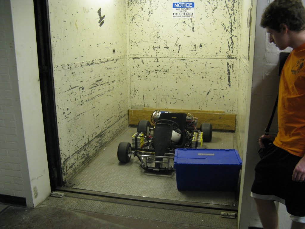
How did we ever do this without a freight elevator?
And lastly, some pictures that should indicate how seriously we are about getting it up and running:


Does anyone know how MOSFETs work??
No comments:
Post a Comment