Friday, November 4, 2011

Hey Shane, why haven't you been working on your motor controllers?

I haven't done much on any of my motor controller projects in a while. For example, DirectDrive hasn't been touched since the July update where it passed a 2.4kVA bench test. And I have yet to do anything other than theorize about sensorless FOC code. And that was so long ago that I would have to reread the post to remember what I was talking about. But now that the season of building and testing vehicles is winding down, and I have sworn off doing any demos, faires, expos, exhibitions, presentations, or showcases until the spring, I can actually have time to get back to motor controllers. For real this time.

First of all, even though I've been relatively pleased with the Kelly KBS36101 controllers on tinyKart, they are frustrating to work with. With the external Hall effect sensors perfectly positioned, the performance at 80A per motor is spectacular. But, if the sensors go out of timing even by just a little bit, the controllers cut out and you lose power to one or both sides. Also, they won't work at all at full current (100A) and they have issues at full speed. (The baseline KBS is only rated to 40,000erpm, which is about 75% of this motor's top speed.) Recently, with the changeover to SK3 motors, the controller bugs have just gotten buggier. So...

I pulled out its heart...
...and put it in a box.
If I'm gonna deal with buggy controllers, they might as well be my buggy controllers. DirectDrive was pretty much designed for tinyKart. If I were as hardcore as I was back in 2008 when we built Cap Kart, I would have put it on from the start. But I guess building the entire chassis was enough of a challenge and we did get quite a lot of use out of the Kelly controllers. Still, screw it, time for the complete power system overhaul.


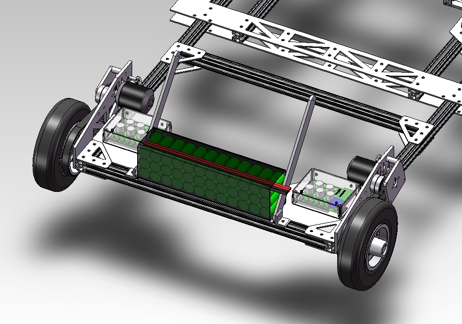
DirectDrive has yet to be tested under any real load, so by committing it to a vehicle, I am forced to solve any to-be-revealed bugs. I guess that means I should also buy more DirectFETs and solder paste, since things rarely go well on the first version of a motor controller. I've only built one so far, but I have enough parts for a second. The payoff will be:
  • More power. DirectDrive is sized for 200A peak at 48V. In this application, assuming it doesn't just outright blow up (it will), it should have no trouble pushing 100A peak at 40V.
  • Sinusoidal field-oriented control. I'm not sure this is directly advantageous on such high-speed, low-inductance motors. But the side effect of having complete control of motor timing in software is worth it. No more screwing around with sensor positioning.
  • Wireless data. I can get vehicle performance data off these controllers, and use the data to help debug failures. (As opposed to the Kelly controllers, where ***  ** is the universal indicator for every possible failure...)
  • Wireless throttle? It worked for Cap Kart.
  • Shedding weight. DirectDrive is a tiny bit lighter than the KBS.
For all that, the only cost is probably dozens of hours of troubleshooting...

You might also notice the new battery pack. I'm tired of worrying about LiPos and am willing to take a ~20% energy capacity cut for the peace-of-mind that comes with A123 LiFePO4 cells. But in order to match the power density of the LiPos, they will have to be m1-B cells. (The green ones, not the paper ones from that DeWalt Drill tree I found.) These have a lower internal resistance, such that a 6lb, 12S3P pack can put out bursts of 6-8kW.

But yeah, messing with tinyKart's Hall effect sensors has reminded me just how much of a pain in the ass it is. It would be really, really nice to never have to play the phase-and-sensor-musical-chairs-wiring-game ever again. I am still very convinced that vehicle-grade sensorless control is a possibility. In fact, we recently found proof:


That is a $28 shady eBay eBike controller, similar to the ones that bailed me out in Singapore. Except, it's sensorless. And the start-up doesn't suck. Unlike RC plane controllers, it ramps the output frequency and voltage gradually at start-up so that you get a smooth acceleration. It also does current (torque) control in both start-up and running modes. It's quite nice on Pneu Scooter and RazEr Revolution. But it's still dumb square wave drive, and it simply refuses to start ultra-low-resistance outrunners. However, it's proof that a smooth ramping start-up is achievable.

So, that will be my first task on the way to full sensorless field-oriented control. Start-up is regarded as the hard part of sensorless control, but for some reason I think it's easy. I will be aiming for a sinusoidal drive current with a ramping amplitude and frequency determined by some estimate of the system inertia. It may need locked-rotor detection or a way to reset and try again if it fails to achieve commutation. But I think it will be pretty easy, actually, compared to the rest of the project:

Once the speed is high enough (10%?), the fun begins. Unlike the $28 version, I will be going for full sinusoidal field-oriented control, with no direct measurement of back EMF. I'm sure this will keep me occupied in software for quite a while. It is my first big software project in a long time...and sadly I'm kind-of excited for it. So much so that I violated one of my long-standing software principles:

I split my build into multiple files. :/
I'll be implementing sensorless field-oriented control first on the 3ph 3.1, Pneu Scooter's controller. It's been totally fine ever since I replaced the FETs that died in Singapore. I'm still not 100% sure what the cause of that failure was, but since I've never seen it before or since, I will assume it was something specific (like bad sensor timing....) or just high ambient temperature and humidity. Once sensorless Pneu Scooter is up and running, I can think about porting it over to DirectDrive.

Let the season of motor controllers begin...

Friday, October 28, 2011

Strobe Attack

The bad thing about having tinyKart around is that we will just keep driving it until something breaks.


Besides drifting the tires off, the only reliability problem I've seen so far with tinyKart is the motors. Electromagnetically, the Turnigy SK-6374-170's are very good. But mechanically, they suck. We already had to replace the left motor at Maker Faire because the entire rotor was loose and would shift axially until the motor locked up. Last week, the right motor suffered the same fate.

Additionally, the outside rotors are out of balance and the sound like they are going to detonate at full speed (7,500rpm). The vibrations are so bad that the entire kart needs to be clamped to a table to do a no-load test, lest it resonate like the giant aluminum flexure it is. And I'm sure all that vibration would eventually lead to more problems.

tinyKart was originally designed with the larger "melon-class" 80mm motors in mind, but the 63mm "grapefruit-class" with KBS36101 controllers is a better match for its size, weight, and performance. When we built it over the summer, the SK-6374-170 was the only 63mm or 80mm motor in stock, so we didn't have much choice. (Well, okay, we could have dropped $360 on Hacker A60's...) But now there is a new line of inexpensive Hobby King motors called SK3, and there are quite a few 63mm ones:

SK-6374-170 (left) and SK3-6364-190 (right).
They look very nice, and the construction quality is definitely improved. The SK3 has a large radial bearing on the shaft side of the rotor, making it far less prone to shaking itself apart violently at high speeds. It should also help better-constrain the rotor axially. My only real problem with the SK3 63mm motors is that they are not actually 63mm:


The outer diameter is 59mm. The stator is proportionally smaller. And because of the can bearing, the active length is reduced as well. The shaft is also smaller: 8mm instead of 10mm. They don't look much different in the pictures but if you held one in each hand you'd clearly be able to tell that the SK3 is a shrunk-down model, probably to cut materials costs while still passing it off as a 63mm motor.

All of this I would be fine with if it was as good, electromagnetically, as the old SK. But the first indication that it is not is the line-to-line resistance: 37mΩ for the SK3-6364-190 as opposed to 23mΩ for the old SK-6374-170. Normally, it wouldn't be fair to compare a 190rpm/V motor to a 170rpm/V motor. But in my testing, the old SK actually was closer to 190rpm/V anyway, so they have virtually the same back EMF constant. So, for a given amount of current, you get the same torque from each, but the new SK3 generates 60% more heat.

Maybe it's not a big deal. After all, the comparable Hacker A60 is 59mm and 32mΩ. Even at 37mΩ, the power lost to winding resistance at 80A is only 237W per motor, or about 10% of the peak power input. If, with more robust motors, the speed can be increased past the 75% please-don't-blow-up limit its been at so far, the peak power might even go up. And tinyKart has never had motor overheating problems. So, it's worth a try. Swapping motors will mean changing the pulleys to 8mm bore, but that's easy. The bigger problem is the Hall effect sensors...


Because the can diameter is 4mm smaller, the sensors are now 2mm farther from the rotor can. They're already relying on the small amount of field leaking out of the side of the can, so every millimeter counts. It turns out they have no trouble picking up the field from the larger distance and I could still time the motor in the normal way. 

But, reverse sucks.

When timed correctly for forward commutation, the reverse is awful. I didn't recall this being the case on the old SK's, but a further test with them confirmed that forward and reverse have always been asymmetric. The extra distance between the sensors and the rotor can, and possibly a thicker rotor can on the SK3, seem to exaggerate the problem. I wasn't 100% sure it was a sensor problem, though. So, I went to borrow a strobotach from the Edgerton Center:

Borrowing a strobotach from the Edgerton Center is kind-of like borrowing an airplane from the Wright Brothers Museum...
This strobotach is an old-school box of vacuum tubes with a giant dial that can adjust the strobe rate. One way to use it is to point the strobe at something spinning at a constant rate and dial the knob until it appears to stop moving. Then, you can read the rpm off the dial. But, I was interested in using the external trigger, which flashes the strobe in response to an electronic signal. I tied this in to one of the Hall effect sensors. The signal bias is 54V for some reason that I'm sure has to do with the vacuum tubes, so I had to make a quick transistor trigger circuit so it would run off the 5V Hall effect signal.


To make a position indicator on the rotor, I passed a fixed current into all six permutations of phase wires and put a tick mark on a piece of yellow tape at whatever fixed position the most was held at by the current. I used three different color tick marks, for A, B, and C phase. There are seven ticks of each color around the motor, since there are seven pole pairs.

The strobe makes it very easy to see where the Hall effect sensor is firing, in forward and in reverse, as well as the physical effect of moving the sensor mount:


The strobe aliases with the video camera's frame rate a bit, but you can definitely see the tick marks. Here are still pictures of the forward and reverse case as well:

Forward.
Reverse.
I had already timed the motor to run properly in the forward direction. So, in forward, the Hall effect sensor (and the strobe) fire almost exactly on a fixed-current motor position (green). A long time ago I convinced myself that this should be the case. But, if it's firing on green in forward, it should be firing 180º electrical out of phase in reverse, or, somewhere about halfway between red and black. Instead, it's firing on the wrong side of black, about 70º away from where it should. The reversing problem is definitely a timing issue, then.

I tried a similar experiment with the old SK, for which the gap between the sensors and the rotor is much smaller, and the reverse mark was still offset from where it should be. But, it was better. Probably enough so that the SK would actually run in reverse, if not happily. I also tried making a flux-concentrating extension for the sensors:

i.e. I glued cap screw heads to the sensors.
This also brought the reverse mark closer to the correct position, but it still was offset by about 60º. I think the problem is due to the Hall effect sensor hysteresis (about 8mT for these sensors). If the field outside the can is weak enough that the total swing is only, say, +/-20mT, then the hysteresis will have a huge effect on the forward/reverse timing.

I could try getting the sensors themselves closer to the rotor, which I think will be better than gluing cap screw heads to them existing ones. I could also try more sensitive Hall effect IC's with a small hysteresis band. Of course, I would not want to have to make bunch of acrylic ones to test all this. Luckily...

Tuesday, October 25, 2011

Melon Checker: Now with more fruits.

I've updated my Hobby King large motor inventory checker:

http://web.mit.edu/scolton/www/aremelons.html

Previously it had only the three "melon"-class motors, so-called because at 80mm OD, they are roughly the size of melons. (So called by whom? What kind of melons? Not watermelons...) These motors haven't been in stock at Hobby King in quite a long time, though they are starting to pop up in other places.

But there are other large motor candidates that are interesting to keep track of, including the brand new shiny SK3 line, which is the new "grapefruit"-class of 63mm motors. Somewhat dissapointingly, the SK3-63xx motors are actually 59mm in outer diameter. (The old 63xx grapefruit-class motors were truly 63mm.)

That said, tinyKart's older-model SK-6374-170 motors are falling apart due to poor construction and lack of a large radial can bearing. (And unrelenting abuse...) I will try replacing them with SK3-6464-190's I bought for a potential tinyKart swap a while ago. They have a  can bearing and should be able to run to higher speeds without shaking themselves apart. They also weigh 1/3lb less, each. But, they have a higher resistance (37mΩ as opposed to 23mΩ), so they will generate more heat and/or less torque. Testing to come soon...

In the large motor category, there is also a durian class and a guava class that are relatively new and nicely-built. If you're interested in inexpensive RC plane motors that can be re-purposed into electric vehicle traction applications, this consolidated inventory list might help you choose.

Wednesday, October 19, 2011

Okay, tinyKart frightens me now.


So it turns out tinyKart was hiding something...


...and by something I mean about half its full power. I know I've had nothing but good things to say so far about tinyKart, but somehow I think I underestimated it. tinyKart. Kicks. Serious. Ass. We need to make more of these things right away and race them against each other.


tinyKart was the Edgerton Center Summer Engineering Workshop's 2011 project. It's an ultralight electric go-kart, something I've dreamed about ever since Cap Kart. The total weight is 55lbs, it fits in the trunk of a car, and it has a trigger throttle. We took it to Maker Faire NY a few weeks ago, and it was a lot of fun. 

But it seems this entire time it's been operating with at least one powered-back controller. The left side Kelly KBS36101 would give a "frequent reset" error and, at high sustained load, cut out entirely, leaving the kart with half power. The right side would also give errors occasionally, but rarely cut out. Then, I tried the parking garage climb and both sides cut out at full throttle. I was getting ready to ditch everything and put in my own controllers.

I guessed that the problem was bad sensor timing. I've seen it before on KBS controllers. The timing is off enough that the drive voltage and back EMF don't match up, leading to current spikes that trigger the controller's protective features. It's exaggerated by the low inductance of the brushless airplane motors. So, I went to carefully re-position the external Hall-effect sensors...


...or actually the entire sensor mount just disintegrated because I failed to remember that Loctite and plastic parts do not play nicely together. For now, I had no choice but to make a new one and forgo the Loctite, but for the future I am switching over to PCB-mounted sensors:


In addition to fixing the sensors in the correct positions and providing for up to 60º (electrical) of adjustment, the board also has a pair of jumpers which can be used to swap two sensor leads, for easy reversing. Much better than having to dig through the software, anyway. These are the first PCBs I've attempted with internal routing, in addition to the curved outside shape. It was a good opportunity to try out MyRO PCB, since Advanced Circuits does not allow internal routing on their $33 Each or Bare Bones deal. (Advanced Circuits' $33 Each deal does handle complex outside dimensions, though, as evidenced by the so-named 4pcb quadrotor.) I've dealt with MyRO before, and it seems okay. So I ordered six of these boards in a tab-routed panel...

...at least, I think I did.
The process I use for "timing" the motors is pretty simple. I set the throttle limit on the Kelly controllers to 30%, so that I can tune the sensors at a reasonable wheels-up speed without much frame vibration. Then, at max (30%) throttle, I move the sensor mount by hand within its 60º (electrical) of adjustable range until the current going into the controller is at a minimum. If the minimum is at an extreme of the adjustable range, I swap motor leads and/or reverse the direction of commutation and try again. 

Minimum current means the back EMF and drive voltage are as close to in-phase as possible. (At no load / assuming zero inductance, blah blah blah.) With the new acrylic sensor mounts, I did this quickly with my clamp meter, then reset the max throttle to 75% (because the controllers and motors may or may not explode above 40,000 electrical rpm.). 

And...well, a new tinyKart was born, apparently. One that is much more evil than the original one. It will happily give full power on both motors now, right up to the motor current limit (80A per side) or the battery input current limit (60A per side), or the maximum throttle (75%), whichever is lower. It accelerates as fast as Cap Kart and might even hit the same top speed if not for the throttle limit. No more play toy...it recorded a peak input power of 4.1kW on the hill climb. And the motors only eat about 200W each to heating at that power, so it's probably putting out very nearly 5hp now.

With the new, scarier tinyKart, I also took the opportunity to re-balance the two front disk brakes and change the steering ratio to give more travel on the steering wheel, and hence more mechanical advantage over the wheels. As if we had actually planned ahead, this only involved moving some pin joints to pre-drilled adjustment holes:

Drive link gets shorter by moving the ball joints closer to the steering column...

...and follower link gets longer by moving the pin joint away from the kingpin.

The length of the tie rods also changes, but that is adjustable by nuts on a threaded rod. I don't think it could have been any easier.

After that, we took it back to the parking garage (along with some other things) and the video above is the result. With 5hp available, narrow drive wheels, and low-traction parking garage concrete, it would happily lose grip coming out of turns, even while hitting the uphill slopes. That was a little surprising. But what I find amazing is that it actually happily re-finds grip as well. It does what I would expect a go-kart to do when I steer against a drift and adjust the power. This thing that we built with 80/20 and McMaster parts behaves the way I think it should, presumably from some experience driving real go-karts... I like it.

Sunday, October 9, 2011

Singapore Post

I was in Singapore again last week for the Singapore University of Technology and Design's first ever Open House.


When I went to Singapore last year, SUTD had just the two upper floors of a Chinese language school, mostly for administrative offices. Now, it has fully moved in to the interim campus, part of the ITE Dover Campus. We built up a small workshop ("the shed" or Gecko Works) at the interim interim campus, which has now been transplanted to a room at the interim campus:


It was cool to see the shop space I helped put together actually being used by future SUTD students and faculty to work on projects. I was expecting the interim campus to have a full shop, since it was formerly part of a technical institute, but it seems Gecko Works is still the primary fabrication space for SUTD. That makes our trip last year seem like a pretty good investment of time, actually.

As you can see in the above picture, Charles and I significantly increased the number of moving vehicles on campus, as usual. But in fact, some of the future SUTD students have been forming an Electric Vehicle Team of their own, using an electric bike we got from MKP Bikes last year as their first vehicle. It's been converted to a chopper bike, and now runs on a frightening amount of lithium polymer battery. You can see it towing half of the SUTD student population here:


Also featured in the video above are a fire ant-motivated top speed test of Pneu Scooter and Charles taking RazEr Revolution's name literally.

Pneu Scooter's officially-measured fire ant-induced top speed: 21mph.
Pneu Scooter actually took its very first test drive in Singapore last year. I finished building the frame and began testing on my 3ph v3.x line of controllers during my last trip. Unfortunately, the v3.0 controller had serious electrical noise issues, so I redesigned it when I got back and wound up with the v3.1, which has been ultra-reliable for almost a year now...

...and then two of them broke on this trip. I don't really know what happened since both times it was being ridden by someone other than myself. (Not that I would know what exactly caused the failure if I was riding it, but I could at least eliminate some possible causes.) My theories are:
  1. The ambient temperature in Singapore is just that much higher than it is in Boston, and the FETs failed due to thermal overload after basically racing it around all day.
  2. Since replacing the rear wheel a few weeks ago, the motor timing had shifted enough to cause commutation failure, leading to a destructive current spike.
I would weight theory #2 a bit more heavily since both controllers (the original and the spare) had the same phase fail. In any case, having burned through even my spare controller and having neglected to pack an extra IXYS module, I went back to MKP Bikes for Plan B: an off-the-shelf e-bike controller similar to the one I used in Singapore last time when my controller also failed. With that, I was able to get through the Open House. When I got back to Cambridge, I promptly changed the FETs on my controller:

Precision MOSFET removal tool.
All the gate drive was in working order, which is unusual after a FET failure. I re-timed the motor and have been riding it around with no issues, so I still have no idea what the problem was. I am going to pretend that nothing ever happened. But I did buy all the GWM100 IXYS modules remaining on the internet.

Scootering around at the Open House was not the only thing I did in Singapore for a week. Earlier, we visited a place called evHUB, which is a Singapore-based electric vehicle conversion and R&D house. They  have a somewhat hidden EV showroom/dealership with the name FSG Mobility Concepts, where I continued my trend of finding Tesla Roadsters scattered around outside the US.


In addition to the Tesla, FSG also carries the YikeBike. Rather than dedicate a paragraph of this post to describing the YikeBike, I'll just put in a video of us attempting to ride it:


I think the evHUB crew had an easier time learning how to handle Pneu Scooter than I had learning how to ride the YikeBike. Also the YikeBike is more expensive than Pneu Scooter by about the same ratio as the Tesla Roadster is to the YikeBike. So I'll stick with the kick scooters for now.

I also brought over 4pcb, my mini PCB quadrotor. It still doesn't fly spectacularly, but I wanted to bring it because I was meeting up with Ali S. to see his somewhat larger quadrotor in action...

Recursive quadrotors...
The exhibition hall actually turned out to be a perfectly reasonable place to fly a mini quadrotor and a perfectly suicidal place to test the one with 10" blades. For that reason, the mini one got a bit more air time. Here it is taking a few short hops:


It still needs work. After returning, I replaced the one weak motor and it at least hovers level now. But at some point in the near future I will replace the IMU with a different board. Not because I think it will necessarily handle the vibrations better, but because I am just sick of dealing with this one. And because Sparkfun doesn't make this one anymore.

I also got to visit most of my favorite Singaporean hobby shops and industrial centers. (I am such a bad tourist...) So overall, another successful trip to Singapore. I don't know how frequently I'll be going back, but I'm sort-of used to the climate and I seem to have a system for dealing with jet-lag. (I just sleep for the entire 25-hour set of flights.) Soon, there will be actual students and classes at SUTD, so maybe I'll go for an entire semester next year.

Because clearly this is my type of university.
For now, though, I have resolved to stop doing anything resembling a demo/expo/faire/whathaveyou for at least a few months. For one, I'm tired of answering misinformed technical questions from the slightly-more-tech-savvy-than-general public. I might just sound cranky but there's only so many times you can explain that MEMS rate sensors are not the same as flywheel gyroscopes without going crazy. Secondly, I am tired of having my vehicles turned into amusement park rides and then having to repair them after every event. And most importantly, I don't actually get any work done on new projects when I'm constantly exhibiting old ones. It's fun, but I need a break, so no more demos until at least IAP.

Now, what was I working on?...

Tuesday, September 20, 2011

Maker Faire NY 2011

Last weekend I went down to the World Maker Faire in New York, along with some of the other builder-types from MIT and the Summer Engineering Workshop crew. Needless to say, we were responsible for most of the rideable objects on our side of the Faire:


I've been to the Cambridge Mini Maker Faire twice, but this was my first experience with one of the three World Maker Faire events. While the Mini Maker Faire probably attracts a crowd of a few thousand, the World Maker Faire numbers must be in the several tens of thousands. First off, I was amazed that a handful of people actually knew me from my blog, so here's a shout-out to the people who came by my table to say hi. I'm not as famous as certain people, but it's cool to meet my blog readers in person.

Also present was Max H., who brought TOBL to show off, and most of the tinyKart crew. A large sampling of the MITERS builders came down from Cambridge as well to show off a pair of sound-reactive EL shutter shades, giant Tesla coil driver, 3D printer, battlebot, tankboard, hub motor kick scooter, eddy current clock, and rideable freakin' hexapod.

For my part, I decided that I would attempt to bring five projects. First, my three Maker Faire veterans, Pneu Scooter, Twitch, and SegStick. Additionally, I brought 4pcb, which turned out to be an attention-getter even though I did not even attempt to fly it. I would say that quadrotors are the new Segways - the current obsession of every random tech-savvy person. But in fact, Segways are still the new Segways. For some reason, no matter what else I bring, I can't escape the Segway people. Then again, I've said a few times that the quadrotor is just two Segways and a FIRST robot, so maybe it's all inherited from one parent class of silly self-stabilizing objects.

So before I get angry, Yes, it does have an angular rate sensor, commonly known as a "gyro" for historical reasons. No, there is no mechanical flywheel keeping it balanced. No, it does not use a Kalman filter. And yes, it runs just fine on an Arduino, and it doesn't even use that much of its processing power because the code is very, very simple...much simpler than you want to think.


And that's all I want to say about quadrotors and self-balancing platforms. But here are the Maker Faire recaps for the more interesting projects:

tinyKart:


That's tinyKart in the trunk of a Ford Fusion. I loaded it into the trunk myself in about 10 minutes. It involved taking out 12 cap screws and sliding the two halves apart, then flipping the front half over so that the steering wheel rested in the seat. The back half weighs less than 40lbs and the front half weighs less than 20lbs. There was even enough extra room in the trunk for Tyler's monster Tesla coil driver.


In terms of making an ultralight, ultra portable go-kart, I consider this trip a huge success. We like to make things that don't exist, and an ultralight electric go-kart is something new. There is the Razor Ground Force, which is the same weight (55lbs) as tinyKart but there really is no comparison. Which brings me to my next point:

tinyKart is absolutely freaking awesome as a go-kart. 

Just look what reverse did to this dude's hair...
We drove it all weekend and it is actually amazing to me that we built such a thing from scratch. It's a totally different experience from Cap Kart and most other go-karts I've driven, and it's more fun than any of them. "Sprightly" might be a good word. I really don't know. It darts around in ways that defy its narrow tires and flex-y frame. The acceleration is good too, despite the lack of more formidable brushless motors. The trigger throttle just makes it even more of a unique experience. And the brakes are so good that I worry about bending the steering wheel from the deceleration force. I really would not change a single thing about the mechanical design...it's pure win.

"If it's going to break, it's going to break now." -Max
It even does things it shouldn't, like off-roading. We took it on slippery grass and dirt, and it was even more fun than on asphalt. The flex-y frame doesn't mind at all and the 17mm aluminum wheel axles, which are probably the weakest link in the structural loop, survived both the shock load from bumps and side load from drifting.

Pretty much the only things that isn't 100% perfect are the controllers. Maybe I just have a high standard for motor control...well okay, I definitely do...but the Kelly controllers just aren't quite up to the task of driving full load into these motors. They cut out occasionally, leaving you with half power for a second or two. I'm learning the acceleration threshold that works, but the motors can handle more power so I feel the urge now to give tinyKart a set of controllers that can, too.

Pneu Scooter:

A few days before Maker Faire, Pneu Scooter got a flat rear tire. I knew it would happen eventually because the front tire got a flat about a month ago. Unfortunately, the 6" pneumatic casters are not conducive to easy tire/tube changes. I thought they would be, which was one of the motivators for using pneumatic tires in the first place, but as it turns out, barring special tooling, it's easier to change the entire wheel. So changing the rear wheel means taking apart the hub motor. But, really, Pneu Scooter has been ultra-reliable, so this is more like scheduled maintenance than a design flaw.

Could use a cleaning while I'm at it...
So I opened the motor for the first time since it was built. The process is pretty simple. The only tricky part is getting the three phase wires out, since they are soldered to connectors. To fit back through the bearing, they needed to be de-soldered and shoved back into the axle slot. Here are some pictures from the teardown, with everything dirty but intact:

Windings.
Outer spacer.
Dirty rotor.
Awesome adapter ring.
After taking off the adapter ring, I could get a good look at the rim and tire to see where the damage occurred. I suspected that the tire and tube had been punctured by screws that hold the ring onto the plastic rim. (The front tire suffered a similar failure.) Sure enough, I found a bunch of slashes like this:


I guess the screws were wearing through the tire and eventually the tube over time. The solution is so simple that I have no idea why I didn't do it in the first place.

Duhhhh...
So I put the motor back together with the shorter screws and Pneu Scooter was back up an running in less than three hours...


...which is great, because it actually came in really handy during Maker Faire. Not only was it the only one of my vehicles that I actually felt reasonably safe letting the annoying little kids ride, but it turned out to be the best way to get from the Citi Field parking lot to the Maker Faire itself. There were shuttle buses, but they were crowded and only took you about 60% of the distance anyway. So, I just took the scooter instead.

Twitch

Twitch also had some lingering wheel problems before Maker Faire. Specifically, the press fit holding the custom aluminum hubs to the plastic Vex omniwheels had failed on one wheel, making it hard to drive. It's happened before and I've resorted to epoxy for a quick fix, but I wanted to make a more permanent solution before the Faire. So, I manned up and got on the lathe...


...and then the mill...


... to turn out some new hubs that will actually bolt onto the wheel instead of relying on a press fit into flimsy plastic. The six-bolt pattern lines up with the spokes such that 1/4-20 screws rest against the inside surfaces to positively transmit torque to the wheel. I only put on one new hub for now, but I have the full set for when the remaining press fits fail. 

As I was doing this, though, some other problems revealed themselves. One of the linkages had a stripped-out hole, and one of the servos that drive the linkages was also damaged. I suspect both were symptoms of the wheels running into hard stops while the servo continues to drive the linkage. So far, I've only been calibrating the servos by hard-coding in soft-stop values, but they change every time I take the robot apart and put it back together.

Twitchguts, if you don't remember.
I decided that after replacing the servo and fixing the linkage, the best way to prevent this problem from happening again would be to just write the damn trim software the way it should be written.


Now the servos each have a software-settable minimum and maximum value. Through some coding trickery I was able to "or" the calibrate state with the normal drive states (forward, sideways, omnidirectional) so that you can trim the servo end positions while in any one of the states. This is useful since the servo maxima occur in the forward state and the minima occur in the sideways state. And just for extra software hacker cred, I save all the trims to a text file that automatically loads when the program starts up.

Twitch was, as usual, a constant source of entertainment that filled in the gaps well while the vehicles were charging. Part of the fun of Twitch is that nobody (or very few people) have ever seen a robot move the way it does. I am finally able to drive it in the way that it deserves, making smooth state changes and combining rotation and translation in ways that just look cool. It took a lot of practice, but I feel like Twitch is finally living up to its potential. And on that note I'll just leave this here...


Tuesday, September 13, 2011

The great XBee 57.6kbps mystery finally solved.

Ever since I started using the STM32F103 microcontroller, I've been hindered by the inability to wirelessly program the way I could with my old MSP430F2274 setup. Which sucks because that's the entire point of the wootstick (Wireless bOOTloading). The wootstick is the MCU board I've used on all my motor controllers:


The latest one, v2.0, has the STM32F103, an FTDI USB-to-UART converter, and an XBee Series 1 digital radio built on to a 3"x1" board with 2mm breakout headers. Ideally, it should:
  • Send and receive data over USB or over the XBee as a virtual COM port to a PC. Switching from USB to XBee wireless is seemless - no software modifications required on either side.
  • Be bootloader programmable through either the USB port or (with some configuration) the XBee radio. The latter option is the most useful to me, since it means the controller can be embedded in an enclosed system and still be programmed.
The USB interface works fine, but up to now, I've been able to get only half of the wireless functionality working. I can either wirelessly bootload or send and receive data over XBee, but not both. Changing from one state to the other requires reconfiguring the XBee, which is impossible if the controller is embedded in, idk, say, a scooter.

I decided I would solve this problem before moving forward on sensorless field-oriented control, or rather, that I would use it as an excuse for not making any progress for so long... I figured it would only take a day of messing around to figure out why exactly this was happening, I just hadn't actually sat down and done it up to now.

Then, as I was spending the last two weeks playing with the PCB quadrotor, I ran into almost exactly the same problem. I tried to set up the Arduino Mini on the quadrotor to be wirelessly programmable, so that I would not have to tether it to my computer every time I want to change the controller. But I found that if I set the radio to the baud rate required for the bootloader (57.6kbps, same as the STM32F103), I would get intermittent communication under radio control. Furthermore, the problem went away under USB control with the same baud rate, which suggested a problem specific to the XBee radios. And I've seen other online sources that suggest XBee trouble at 57.6kbps. So I decided to dig a little deeper.

Step one was to round up all my XBees, minus the two high-power transceivers that I have yet to get back from certain unscrupulous borrowers.
Step two was to find a real scope.
As much as I love the Tek 2445 analog scopes in MITERS and the Edgerton Center, I absolutely needed a digital scope to see what was going on at the bit level of the PC-to-XBee-to-microcontroller serial communication. So I went down to the mechatronics lab, which I now have access to since I am apparently the TA for a new course. (Have you heard?!) And there are 12 brand-new four-channel Agilent digital storage oscilloscopes with all kinds of fancy features. They can even save waveforms as .png images to a flash drive. (Something I did not find out in time for this post, as you'll soon see.)

Anyway, based on internet rumors, I suspected a problem with baud rate timing mismatch between the computer, XBee, and microcontroller. All are nominally set to 57.6kbps, but due to the limited clock frequency dividers on the XBee and the microcontroller, there is some error. First, the PC:


I zoomed way in on the first (start) bit of the transmission, something only possible with a nice set of working trigger and holdoff settings on the new scopes. The bit width is 17.34μs/b, the inverse of which is 57.67kbps. Within the error tolerance of the measurement, that's exactly correct. Next, the XBee:


A single bit on the XBee Tx pin was 17.00μs wide. This is 58.824kbps, which is what the internet suggests a XBee set to 57.6kbps actually is. The reason for this is because the XBee has a 16MHz crystal and an integer divider the produces the buad rate. If the integer divider is of the form 16MHz/(16*N), and N=17, then the exact baud rate is 58.824kbps. The next integer up, N=18, would yield 55.556kbps, which has a higher error than N=17. So the XBee uses N=17 assumes the PC can deal with the 2.1% error in baud rate, which it can.

Now here is where it gets interesting. The Arduino, when configured with Serial.begin(57600), showed up with a bit rate of 17.50μs. (Sorry, forget to take a picture of the scope...) This is 57.140kbps. It's consistent with an integer divider of the form 16MHz/(8*N) with N=35, and digging into the Arduino serial library source code suggests that this is in fact what happens. With an error of less than 1%, it's preferred over N=34, which would make it exactly equal to the XBee rate. 

But, the error on the XBee is in the opposite direction as the error on the Arduino. So the total error of an XBee talking to an Arduino at 57.600kbps nominal is close to 3%. This is flirting with the maximum error tolerance of the USART, according to the ATmega328 reference manual, page 193. (Seriously, RTFM, you will not find this information on www.arduino.cc.) When you factor in the +/-1% error tolerance of the ceramic resonator used to generate the Arduino's 16MHz clock, the chance for framing errors increases even more.

Why exactly it works in the bootloader but not during normal data transmission, I don't know. Maybe it has trouble picking up bytes that are adjacent to each other, or maybe the bootloader just has better software error checking to verify the program data is correct. In any case, I took the safe route and forced the Arduino baud rate to match the XBee baud rate exactly:

  Serial.begin(57600);
  UCSR0A |= (1 << U2X0);
  UBRR0L = 33;

Which, now that I look at it, should be the same as:

  Serial.begin(57600);
  UCSR0A &= ~(1 << U2X0);
  UBRR0L = 16;

It's 16MHz / [16 * (16 + 1)] instead of 16MHz / [8 * (33 + 1)]. (RTFM on page 179.) The latter is preferable because slow mode has a wider error band. Either way, it forces the Arduino to have a bit rate of 58.824kHz, matching the XBee. This made the RC control much happier, and the bootloader still works. (It should be independent of the user code.)

But that was all for the Arduino. To test the clock speed deviation theory on the STM32F103, I took out DirectDrive and brushed the dust off of it:

Wasn't I going to do something with this?
I checked the USART documentation for the STM32F103 against my code only to find that the USART clock divider has significantly more resolution. Instead of an integer clock speed divider of the form 16MHz/(16*N) it is essentially 16MHz/N, and I have N=278. (For some reason, it's not quite that simple, RTFM page 768.) But the result is that it should be (and is) running at 57.55kbps. The error between this and the XBee baud rate should be within tolerance of the USART.

Additionally, sending and receiving data works just fine on the STM32F103 at 57.6kbps with 8-N-1 configuration. Only when set to 8-E-1 (even parity bit, required by the bootloader) would the wireless data transmission stop working. But the bootloader worked fine on 8-E-1, with the XBees properly configured for even parity. So now I had at least narrowed it down to a problem involving the parity bit configuration.

Interestingly, I had unknowingly managed to avoid the problem over USB, set at 57.6kbps 8-N-1, because the FTDI chip would automatically reconfigure to 8-E-1 when using the bootloader, then switch back to 8-N-1 when running user code. Only because the XBee radios are have a fixed parity setting did the problem seem to be a wireless-only issue.

I think the theme of this post is Read The Fucking Manual because after only about 10 minutes of doing just that, I found the answer:

It's right there on page 791.
Essentially, by setting the PCE bit, I thought I was appending a single, even parity bit to the end of the data frame, making it 8-E-1. Instead, it was replacing the last data bit with the parity bit, making it 7-E-1, and screwing up the entire data protocol. Only by changing the word length to 9-bit by setting the M bit could I get 8-E-1. I should point out that no other microcontroller that I've used does it this way. Setting the parity enable bit appends a parity bit to the data frame on the ATmega328 and the MSP430F2274.

Well, with that sorted out, everything works properly now. The flash bootloader works over XBee and I can send and receive data at 57.6kbps, 8-E-1. Clearly the next thing to do is go back to working on sensorless control make MIDI scooter play Railgun.