 |
| I promise I will put it away soon... |
After some reasonable success with the new digital IMU, I decided to play around with the digital filters built into the L3G4200D 3-axis gyro to see if I could improve the performance a little more. (The accelerometer is already heavily-filtered by the complementary filter, so no need to focus much attention on that.)
In previous testing, I had determined that the gyro rate signals were incredibly noisy and that the source of the noise was not electrical but rather mechanical frame vibrations. This is a common problem and, according to many people, it can most often be solved by mounting the sensors with foam tape. For some reason, foam tape alone is not enough on this frame, so I have to resort to heavier filtering:
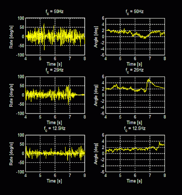
From top to bottom, the graphs represent digital low-pass filters (built into the gyro) with cutoff frequencies of 50Hz, 25Hz, and 12.5Hz. The left plots are the rate signals when the quadrotor is held level and the motors are run at full throttle. The right plots are the angle computed by the complementary filter.
Noise in the rate signal can cause trouble in two ways: (1) directly, by being amplified through the derivative (D) term in the control loop, and (2) indirectly, by causing random drift in the angle calculated by the complementary filter. I actually think the second problem is the bigger one, since the angle drift occurs on a long enough time scale that it doesn't get averaged out by the mechanical system. I noticed while flying that the quadrotor would drift a lot and sometimes quickly dart off in one direction, something that could be caused by the sharp jump in angle seen in the right-middle graph.
With heavier digital low-pass filtering, the rate signal noise is significantly reduced. The angle estimate is also more stable. The trade-off is dynamic performance. With a 12.5Hz low-pass filter, command inputs faster than that cannot be tracked. A 12.5Hz low-pass filter has a rise time of about 20ms. I tried flying with this filter and the improvement in static hovering ability greatly outweighs any decrease in response time. Here's some new video:
It doesn't drift as much and the random darting is significantly reduced, at least to the point where it can be controlled. It still lacks altitude control, so maintaining height is difficult. But the improvement just by tweaking the filters is pretty neat.
I also finally compiled the documentation for this project. It's certainly not a fully-tested and user-friendly kit, but if you want to make your own, here is the documentation folder:
4pcb_DOC.zip (1.38MB)
It's also on the project page. It contains:
- Full bill of materials
- EAGLE files
- Gerber board files
- Schematic
- Arduino project
- Executable control station GUI
- Control station GUI source (VB .NET)
- Picture showing mounting of IMU
The most important change from the original schematic is that the Sparkfun IMU, which has been discontinued, is not used. Instead, the Pololu minIMU-9 is externally wired into SDA, SCL, +5V and GND. Since the IMU needs to be creatively mounted on a ball of foam tape anyway, I did not include it in the board schematic. The power wiring to the motor control chips is also done externally, connecting to the pads near each chip. In a future version of the board I may clean all this up.


hI, I need to put AA=0.999 for my complementary filter and filter ACC to LPF at 5Hz...because my noise acc is a lot. You think can be a problem??
ReplyDeletealexzupo@libero.it