
Monday, August 31, 2009

Sunday, August 23, 2009
It Coexists.
I guess I'm not very good at this whole "documentation of incremental progress" thing, but anyway the B.W.D. Scooter is done and it's probably time to write up my build report. (The official documentation is now on the web, in our usual single-obnoxiously-long-page format.) This is merely my personal take on the project.
If you remember, this is round three of the Edgerton Center Summer Engineering Workshop, a unique educational program in which I get told what we are to build by a group of insane high school students. (To be fair, most of them aren't really in high school anymore, they're all off to college now to actually learn.) So maybe it's not an educational program; maybe it's more of an ad-hoc group with similar interests in things that move. Either way, good luck finding a better project team anywhere.
Oh, right, the scooter. Well, I wanted to build The Magscooter, a scooter that uses the Magmotor S28-150, a three horsepower motor famous for its utter combat-robot-propelling power in a light-weight package. Imagine that belt-driving a Razor scooter wheel. It would be the definition of overkill, and we could have built it in a matter of weeks. Except I was told that not only is that a lame idea, but also that I am unimaginative, boring, and risk-averse. So the idea for the B.W.D. scooter was born. The Summer Engineering Workshop crew decided to rip off Charles Guan and create a scooter with not one but two integrated wheel-hub-motor-things.
 Wheel-hub-motor-thing. (Charles Guan's Project RazEr)
It turns out that it isn't all that hard to build a motor. To get it inside the wheel, the name of the game is brushless. The stator, with coils of copper magnet wire, sits stationary inside the wheel. The rotor, with permanent magnets, spins around it, held in place by side plates with bearings. This "outrunner" configuration is common in computer fans, hard drives, and model airplane propeller drives. There is also a lot of online documentation on how to re-wind or otherwise build custom BLDC motors.
Except...what do fans, hard-drives, and airplane props have in common? They see their highest load at high speed. Direct-drive BLDC motors that spin up to N,000 RPM make total sense for these applications. A scooter (or other electric vehicle), on the other hand, needs low-end torque, and a lot of it. And with hub motors, there is no gear reduction.
Turns out there are two keys to getting low-end torque from a motor. One is good control, which I already spent some time ranting about. The other is squeezing as much Lorentz force (F=ILB) as possible out of the motor geometry. (Ok, it's not really Lorentz force when you have steel carrying flux...but whatever.) It boils down to a good deal of current (I), a relatively wide motor (L), and many large, strong magnets (B). We started with the magnets, opting for the 12-slot/14-pole "LRK" style that Charles used. That gives plenty of surface area for mangetic interaction, and has the added benefit of reduced cogging torque because of the fractional slot:pole ratio, something we might have learned if we had paid more attention in Monaco. (Seriously...there was actually a keynote presentation about it.) Armed with the basic idea, we generated a design:
 Don't you wish your CAD software could do that? (Render credit: Max H.)
Wow that looks really hard to make...even with six abrasive waterjets. But what we lack in Charles' extreme fabrication skillz, we make up for in the ability to get other people to give us nice things for free. Like, for example, laser-cut M19 steel laminations:
 Stators not to be used as ninja stars.
Except...what do fans, hard-drives, and airplane props have in common? They see their highest load at high speed. Direct-drive BLDC motors that spin up to N,000 RPM make total sense for these applications. A scooter (or other electric vehicle), on the other hand, needs low-end torque, and a lot of it. And with hub motors, there is no gear reduction.
Turns out there are two keys to getting low-end torque from a motor. One is good control, which I already spent some time ranting about. The other is squeezing as much Lorentz force (F=ILB) as possible out of the motor geometry. (Ok, it's not really Lorentz force when you have steel carrying flux...but whatever.) It boils down to a good deal of current (I), a relatively wide motor (L), and many large, strong magnets (B). We started with the magnets, opting for the 12-slot/14-pole "LRK" style that Charles used. That gives plenty of surface area for mangetic interaction, and has the added benefit of reduced cogging torque because of the fractional slot:pole ratio, something we might have learned if we had paid more attention in Monaco. (Seriously...there was actually a keynote presentation about it.) Armed with the basic idea, we generated a design:
 Don't you wish your CAD software could do that? (Render credit: Max H.)
 Stators not to be used as ninja stars.
These parts were generously donated by Proto Laminations, a company that specializes in producting low-quantity prototype motor laminations from electrical steel. The purpose for lamination is to reduce the circular eddy current that can flow in the steel as a result of the changing magnetic field. For us, the added benefit was the ability to design the motor exactly as we wanted. The biggest design feature this allowed were the small indents on the rotor for placing rectangular magnets. This saved us countless hours of aligning and gluing them in place.
That's not to say we didn't get to use the waterjet at all. Turns out winding magnet wire around sharp steel corners is not the ideal way to make a motor. Covering said corners with electrical tape also doesn't help much when you have to keep a lot of tension on the wire just to keep it wound tightly. Red fiberglass and abrasive waterjet to the rescue:
 Who says you can't cut fiberglass on the waterjet?
That's not to say we didn't get to use the waterjet at all. Turns out winding magnet wire around sharp steel corners is not the ideal way to make a motor. Covering said corners with electrical tape also doesn't help much when you have to keep a lot of tension on the wire just to keep it wound tightly. Red fiberglass and abrasive waterjet to the rescue:
 Who says you can't cut fiberglass on the waterjet?
These slightly oversized stator replicas prevent the wire from digging into the steel corners. They also look sick, and match our color scheme. But wait, they're inside the motor, right? So nobody will see them. Unless of course we already had planned to make the motor sides transparent. Seems stupid, right? Why waste all that flux out the sides and risk the entire structural integrity of the wheel for the ability to see inside? You'll see...
But first, the windings. How did we know how many windings to put? Too few and your torque will suffer...too many and the back EMF generated will limit your top speed. Too thin and the motor won't be able to carry enough current. Too thick and winding them will be very difficult. There are four ways to deal with this question, and we did all four:
 We made these?
But first, the windings. How did we know how many windings to put? Too few and your torque will suffer...too many and the back EMF generated will limit your top speed. Too thin and the motor won't be able to carry enough current. Too thick and winding them will be very difficult. There are four ways to deal with this question, and we did all four:
- Copy someone else. Charles put 25 turns per tooth. We decided to wind every other tooth...so we should have a bit more.
- Try to do math. Well, we tried.
- Simulate. FEMM to the rescue. Pretty...

- Just freaking build one. The only real unknown is the "geometry factor" that is defined by the shape of the motor and the placement of the magnets. Motors are forgiving. The chance of making one that just completely doesn't work at all is very slim. So we built one with a low number of turns, 30, and then measured its performance. Turns out it was not far from where we predicted, but we wanted a bit more torque and less speed. So, with the geometry factor solved for, all we had to do was adjust the number of turns accordingly and we would know exactly the specs of the second motor. Single iteration; the high torque motor got 45 turns.

 We made these?
Here's where anyone familiar with motors will criticize: Wow, even the high torque motor (left) isn't even half-full of windings. That could get so much more power with every tooth wound or with thicker wire. You try hand-winding a motor. But otherwise, I agree, it just looks weird. Most motors are packed full of copper wire. These could probably be two-horsepower motors if the winding density was better. But the math, simulation, and actual real-life test drives all confirm that these have plenty of torque for a scooter and they operate fairly efficiently, so the battery will last a good ways. Remember, more windings = more power, but the power still has to come from the batteries.
As for the efficiency hit, well I though this would be a problem too but it turns out that at low current (and by low I mean 20A), copper losses are small and interesting things start to happen to the efficiency curves. The benefits of brushless, low-speed, low-friction operation start to make even these hand-built motors seem like good alternatives to things like the Magmotor.
 Well now that doesn't seem bad at all.
As for the efficiency hit, well I though this would be a problem too but it turns out that at low current (and by low I mean 20A), copper losses are small and interesting things start to happen to the efficiency curves. The benefits of brushless, low-speed, low-friction operation start to make even these hand-built motors seem like good alternatives to things like the Magmotor.
 Well now that doesn't seem bad at all.
Okay, so the sparse windings don't really hurt much. What about the flux that leaks out those plastic sides? That must not be good. Well...since the stator is only 1" wide, centered in the rotor, I'd guess that the flux that counts is in that 1" band, where it is still quite straight. The flux leaking out the sides wouldn't be doing much other than short-circuiting to the other side of the magnet, even if the sides were steel. Not convinced? Still think something is being wasted? Okay, let's capture it and use it as a signal for the motor controller.
 External hall-effect sensors!?!???
 External hall-effect sensors!?!???
Yes, I wish we could say we planned this the whole way. Actually, we were originally going to use an optical encoder track. (Because the motor is brushless, the controller needs some way of knowing where the rotor is to control which coils are active.) But after noticing that the wheels had a tendency to pick up loose hardware off the floor, we though that perhaps there might be enough of a field coming through the sides to use hall-effect sensors. Many brushless motor have embedded sensors, but having them on the outside is actually extremely useful. You can find the right position very easily by rotating them with respect to the stator while testing the motor. You can also make minor tweaks to the torque/speed characteristic by rotating them.
So with the motors taken care of, we had to actually build the scooter itself in just about three weeks. Not a problem. Since there's no gearing or anything, it's really just a matter of making a frame with some forks to hold the two wheels. The deck is some folded 1/16" sheet aluminum. The rear fork is pretty straightforward:
 Bandsaw clamp forks.
So with the motors taken care of, we had to actually build the scooter itself in just about three weeks. Not a problem. Since there's no gearing or anything, it's really just a matter of making a frame with some forks to hold the two wheels. The deck is some folded 1/16" sheet aluminum. The rear fork is pretty straightforward:
 Bandsaw clamp forks.
The front was a bit trickier, since we decided to work with the existing Razor scooter handlebar. Since the wheel is significantly wider and larger in diameter than the original wheel, we had to add an offset fork:
 Front fork and steamroller wheel.
 Front fork and steamroller wheel.
That's it right? Oh wait the batteries! We acquired a pack of A123 26650 cells, totaling 33V and 4.4Ah. Interestingly, when laid flat, they have only about 30% more energy by volume than a lead-acid pack. But they weigh a good deal less and most importantly they can source immense amounts of power for their size thanks to extremely low internal resistance. Cramming them in the deck was interesting...
 Batteries in all the available space under the deck.
 Batteries in all the available space under the deck.
One thing we do pretty well is make things look good. That's where the carbon fiber deck and red LED trim lights come in:
 And there you have it...
 And there you have it...
So that's it. It's not without its flaws. The urethane is being held on by "Plastic Steel Steel Weld Epoxy," which didn't last long. (The rear wheel tread came off once already.) The front of the deck needs reinforcement. And the whole thing is in serious need of some more nylon lock nuts. The vibrations are killer, especially in the ongoing roadwork nightmare that is Cambridge. But overall, it is functional and fun to ride. It's lightest and most compact of our fleet (yes, it's a fleet now), so it will probably see the light of day a lot more.
What have I learned? Motors are forgiving. Controllers are not, but if you overdesign them they might survive. Vibration sucks. Vehicles that carry seven times their own weight are awesome. Scooters are fun to ride. Make two of everything. Most importantly, probably, do something fun with a good team and you really can't go wrong.
What have I learned? Motors are forgiving. Controllers are not, but if you overdesign them they might survive. Vibration sucks. Vehicles that carry seven times their own weight are awesome. Scooters are fun to ride. Make two of everything. Most importantly, probably, do something fun with a good team and you really can't go wrong.
Sunday, July 26, 2009
Silence of the Cows
I was just thinking about how boring it would be to have a website that just exhibits a bunch of working projects, no matter how cool those projects are. Not very many of my projects make it to a working state in one shot, but one that came frighteningly close is my 3-phase motor controller. Version 0.0 was built as a term project for 6.690/6.061 (Intro. to Electric Power Systems). It was built in a week and worked with no problems on a small (200W is small around these parts...) induction motor, running a simple V/f control. I commented then that it was only a matter of time before it got scaled up...

So I made it smaller. Scaling up doesn't always mean it has to be bigger. What I call v1.0 is just a tad over 80mm x 100mm x 40mm. (This is the maximum board size in the free version of Eagle...) It's got six IRFreakingBig3207 MOSFETs on board right underneath a tiny (60mm x 10mm) but strong fan. As usual, I have already gotten my fingers owned by said fan. The heat sinks are not that great, just slivers of aluminum soldered to the circuit board. (Yes, you can solder aluminum.) But based on my previous experience with these FETs, I sort-of expected that they could do the job.
 The job.
The job, by the way, is full torque control of a brushless DC motor built into the hub of a Razor scooter wheel, a la Charles Guan. It's the Summer Engineering Workshop '09 project, which means two things: 1) It will be cool. and 2) I will spend a lot of time making electronics for it. Sigh. Although unlike last year, we could actually buy a controller that does exactly what we want. Granted, this is pretty much the only one in existence and the manual refers to a color called "Reddle", which I suspect probably means orange, but it is still cheaper than making one. But when has that ever stopped me?
But wait, what about all those tiny RC plane controllers that can handle 100A? Well, first of all there aren't many that can run higher than 24V, and with these insane neodymium magnets the backEMF is going to be huge. But more importantly, they are not torque controlled. You set the throttle and they adjust the PWM to give you a proportion of the full voltage. This works fine for airplane propellors, which see increasing torque with increasing speed in a nice drag-based relationship. Electric vehicles, on the other hand, see max torque when they are sitting still. This means no forced-air cooling of the controller, and quite possibly if it is completely stalled two phases will take all of the load, so the current ratings would be much lower.
The key to torque control is the ability to measure and control current, which means putting a current sensor on the controller. In fact, it should mean putting TWO current sensors on the controller, since only two of three phases are active at any given time and you need at least two sensors to be guaranteed a measurement of an active phase. I manage with only one. I wish I could say it was clever design that allowed this, but instead it was just stupidity. I put the current sensor on the DC link...before the power gets inverted and sent to the motor.
 Oops.
Oops.
So there is mistake #1. I'm glad there was at least one...because otherwise I'd just have to write about how it works. The fix for mistake #1 is somewhat of a hack. In software, I can estimate the current going to the motor based on the PWM and the DC link current. There is a horrible divide-by-zero condition inherent in this, though. (Imagine the motor is spinning full speed and then the PWM goes to zero, shorting all the phases together.) So, something to think about for v2.0 is repositioning the current sensors to a place that makes sense.
But does that mean that v1.0 actually works without any wire hacks, any desoldering, any exploded FETs, any melted Zener diodes?! I think I would actually be sad if it did. Only load testing can tell. At 20A, no problems:
Even on a huge Etek motor, it effectively regulates the current in both directions. (Yes, it can do controlled regenerative braking.) This is actually a great demonstration of the torque control, because if you hooked up an RC controller to an Etek and went full throttle, there's a good chance it wouldn't survive, since it would apply the full voltage regardless of the N-hundred amps the Etek wants to draw. And 20A is about what we can put through the scooter motor before the windings start to heat up too much. But come on! I need to at least be competitive with the Kelly controller current ratings. Bring on the CIM-battle load test:
 Mmmmm...ex-FIRST equipment.
These are wonderful 1/2-horsepower CIM motors from an old FIRST Robotics kit, in a nice cast-aluminum gearbox. They are meant to turn with each other for double the torque, but I prefer to make them fight each other by hooking red to black, black to red, and driving them with a single phase of the 3ph controller. If a single phase can handle the load, three phases sharing it should have no problem. So this should make a great worst-case scenario test. Let's try 50A!

Uh oh! At anything above 30A, it seems the controller has a tendency to produce a sound that I can only describe as "mooing." Yes, like a cow. It still works, but some low-frequency noise is coming in somewhere that makes the motors sound like they are ready to be milked. I originally thought it was some digital instability introduced by my current sensor hack, but after changing the gains and seeing no difference, I concluded that it was a real hardware problem! Hooray! There is something wrong with the design that isn't just a "no big deal I'll fix it in version 2.0." I actually get to troubleshoot something significant and fix it!

Well, that was easy. The 15V DC/DC converter which powers...everything on the board...needs an input capacitor closer to its...input. I thought the main caps would be sufficient but since they are on the opposite side of the high-side bus bar, all their effort goes into keeping the MOSFETs happy and they can't really help the DC/DC all that much. In power electronics, where you put things is almost more important than what you put. I should probably know that by now. But at least I have something to write about now.
The rest of the load testing went as expected. 50A for 60 seconds no problem. 75A for 45 seconds and then a shower of sparks as the heat sink melted through the high side input line which happened to be resting on it.
 Not good.
A repeat of the 75A test almost made it to 60 seeconds, but then the MOSFETs started desoldering themselves. (They do that before they fail...amazingly.) So that's about the upper limit...for one phase. Call it 100A peak, 65A for one minute, 40A continuous. (I just made that up.) With all three phases running, I suspect this goes up at least by a factor of 1.5 or 2. Although at that point our scooter motor would be quite destroyed and our batteries would be dead.
So, the mooing has stopped, the controller works, and things look good for motor testing in the next week or so. But it wasn't easy. It shouldn't be. I hope it never is. Here is the v1.0 schematic and design files for anyone who might find it useful.

So I made it smaller. Scaling up doesn't always mean it has to be bigger. What I call v1.0 is just a tad over 80mm x 100mm x 40mm. (This is the maximum board size in the free version of Eagle...) It's got six IRFreakingBig3207 MOSFETs on board right underneath a tiny (60mm x 10mm) but strong fan. As usual, I have already gotten my fingers owned by said fan. The heat sinks are not that great, just slivers of aluminum soldered to the circuit board. (Yes, you can solder aluminum.) But based on my previous experience with these FETs, I sort-of expected that they could do the job.
 The job.
The job, by the way, is full torque control of a brushless DC motor built into the hub of a Razor scooter wheel, a la Charles Guan. It's the Summer Engineering Workshop '09 project, which means two things: 1) It will be cool. and 2) I will spend a lot of time making electronics for it. Sigh. Although unlike last year, we could actually buy a controller that does exactly what we want. Granted, this is pretty much the only one in existence and the manual refers to a color called "Reddle", which I suspect probably means orange, but it is still cheaper than making one. But when has that ever stopped me?
But wait, what about all those tiny RC plane controllers that can handle 100A? Well, first of all there aren't many that can run higher than 24V, and with these insane neodymium magnets the backEMF is going to be huge. But more importantly, they are not torque controlled. You set the throttle and they adjust the PWM to give you a proportion of the full voltage. This works fine for airplane propellors, which see increasing torque with increasing speed in a nice drag-based relationship. Electric vehicles, on the other hand, see max torque when they are sitting still. This means no forced-air cooling of the controller, and quite possibly if it is completely stalled two phases will take all of the load, so the current ratings would be much lower.
The key to torque control is the ability to measure and control current, which means putting a current sensor on the controller. In fact, it should mean putting TWO current sensors on the controller, since only two of three phases are active at any given time and you need at least two sensors to be guaranteed a measurement of an active phase. I manage with only one. I wish I could say it was clever design that allowed this, but instead it was just stupidity. I put the current sensor on the DC link...before the power gets inverted and sent to the motor.
 Oops.
Oops.So there is mistake #1. I'm glad there was at least one...because otherwise I'd just have to write about how it works. The fix for mistake #1 is somewhat of a hack. In software, I can estimate the current going to the motor based on the PWM and the DC link current. There is a horrible divide-by-zero condition inherent in this, though. (Imagine the motor is spinning full speed and then the PWM goes to zero, shorting all the phases together.) So, something to think about for v2.0 is repositioning the current sensors to a place that makes sense.
But does that mean that v1.0 actually works without any wire hacks, any desoldering, any exploded FETs, any melted Zener diodes?! I think I would actually be sad if it did. Only load testing can tell. At 20A, no problems:
Even on a huge Etek motor, it effectively regulates the current in both directions. (Yes, it can do controlled regenerative braking.) This is actually a great demonstration of the torque control, because if you hooked up an RC controller to an Etek and went full throttle, there's a good chance it wouldn't survive, since it would apply the full voltage regardless of the N-hundred amps the Etek wants to draw. And 20A is about what we can put through the scooter motor before the windings start to heat up too much. But come on! I need to at least be competitive with the Kelly controller current ratings. Bring on the CIM-battle load test:
 Mmmmm...ex-FIRST equipment.
These are wonderful 1/2-horsepower CIM motors from an old FIRST Robotics kit, in a nice cast-aluminum gearbox. They are meant to turn with each other for double the torque, but I prefer to make them fight each other by hooking red to black, black to red, and driving them with a single phase of the 3ph controller. If a single phase can handle the load, three phases sharing it should have no problem. So this should make a great worst-case scenario test. Let's try 50A!

Uh oh! At anything above 30A, it seems the controller has a tendency to produce a sound that I can only describe as "mooing." Yes, like a cow. It still works, but some low-frequency noise is coming in somewhere that makes the motors sound like they are ready to be milked. I originally thought it was some digital instability introduced by my current sensor hack, but after changing the gains and seeing no difference, I concluded that it was a real hardware problem! Hooray! There is something wrong with the design that isn't just a "no big deal I'll fix it in version 2.0." I actually get to troubleshoot something significant and fix it!

Well, that was easy. The 15V DC/DC converter which powers...everything on the board...needs an input capacitor closer to its...input. I thought the main caps would be sufficient but since they are on the opposite side of the high-side bus bar, all their effort goes into keeping the MOSFETs happy and they can't really help the DC/DC all that much. In power electronics, where you put things is almost more important than what you put. I should probably know that by now. But at least I have something to write about now.
The rest of the load testing went as expected. 50A for 60 seconds no problem. 75A for 45 seconds and then a shower of sparks as the heat sink melted through the high side input line which happened to be resting on it.
 Not good.
A repeat of the 75A test almost made it to 60 seeconds, but then the MOSFETs started desoldering themselves. (They do that before they fail...amazingly.) So that's about the upper limit...for one phase. Call it 100A peak, 65A for one minute, 40A continuous. (I just made that up.) With all three phases running, I suspect this goes up at least by a factor of 1.5 or 2. Although at that point our scooter motor would be quite destroyed and our batteries would be dead.
So, the mooing has stopped, the controller works, and things look good for motor testing in the next week or so. But it wasn't easy. It shouldn't be. I hope it never is. Here is the v1.0 schematic and design files for anyone who might find it useful.
Wednesday, July 1, 2009
The epic journey of the spinning disks of doom.
Well, maybe not epic, but at least humorous. The spinning disks of doom were five "steel" plates I ordered from Big Blue Saw because they were cheaper than material + machining time at MIT even though we have six abrasive waterjets. Go figure. I say "steel" because the first set I got was aluminum. I had actually figured out this mistake before they arrived because the shipping weight was off by exactly the ratio of densities. Anyway, I eventually got the steel plates and installed them for motor testing:
 DO NOT TRY THIS AT HOME...OR ANYWHERE.
This was an incredibly bad idea. 55lbs of steel dangling off the edge of a motor shaft with no other bearings and no enclosure is a disaster waiting to happen. It happened to be very well balanced due to the fact that the waterjet cuts the ID and OD at the same time, and it ran very quietly, but NO NO NO DO NOT DO IT. It stores as much energy as 500 lbs moving at 40mph. This makeshift inertial dynamometer provided some invaluable testing data for the kart regen system, and then I decided it must be destroyed. It was the most dangerous thing I've ever built, and I decided this while standing next to a 110F ultracapacitor on an electric go-kart...
So where do flywheels go to die? When I got involved with the MIT Electric Vehicle Team outreach project, they were looking to make a tabletop demonstration of regenerative braking. Sounds familiar. Turns out they had enough time to do it the right way...bearings, hubs, enclosure, etc. It was also much smaller...8" instead of 14" diameter disks. So, I gave them the plates and they produced a mini-flywheel out of the insides:
 Much more sane.
So that takes care of the donut holes, but then what do you do with a bunch of 1/4" steel donuts? Pretty useless, right? Not if you believe in conservation of usefulness. After looking around for a microwave transformer or something to smooth out some extremely high battery charging current, also for an EVT project, I remembered these donuts. Toroidal inductor core!
 Also surprisingly less dangerous than the previous usage.
Yes, I know this is not a great inductor, as a lot of field is wasted in the excessively-large steel ring. But according to some maths it is >200uH, which is good enough for the job. The job, btw, is insane-charging a motorcycle Li-Ion battery pack. (4-6C charge rates.) This will smooth out the 100A charge to about a 5A or 10A ripple current. Hopefully...
In any case, the spinning disks of doom have found new homes.
 DO NOT TRY THIS AT HOME...OR ANYWHERE.
This was an incredibly bad idea. 55lbs of steel dangling off the edge of a motor shaft with no other bearings and no enclosure is a disaster waiting to happen. It happened to be very well balanced due to the fact that the waterjet cuts the ID and OD at the same time, and it ran very quietly, but NO NO NO DO NOT DO IT. It stores as much energy as 500 lbs moving at 40mph. This makeshift inertial dynamometer provided some invaluable testing data for the kart regen system, and then I decided it must be destroyed. It was the most dangerous thing I've ever built, and I decided this while standing next to a 110F ultracapacitor on an electric go-kart...
So where do flywheels go to die? When I got involved with the MIT Electric Vehicle Team outreach project, they were looking to make a tabletop demonstration of regenerative braking. Sounds familiar. Turns out they had enough time to do it the right way...bearings, hubs, enclosure, etc. It was also much smaller...8" instead of 14" diameter disks. So, I gave them the plates and they produced a mini-flywheel out of the insides:
 Much more sane.
So that takes care of the donut holes, but then what do you do with a bunch of 1/4" steel donuts? Pretty useless, right? Not if you believe in conservation of usefulness. After looking around for a microwave transformer or something to smooth out some extremely high battery charging current, also for an EVT project, I remembered these donuts. Toroidal inductor core!
 Also surprisingly less dangerous than the previous usage.
Yes, I know this is not a great inductor, as a lot of field is wasted in the excessively-large steel ring. But according to some maths it is >200uH, which is good enough for the job. The job, btw, is insane-charging a motorcycle Li-Ion battery pack. (4-6C charge rates.) This will smooth out the 100A charge to about a 5A or 10A ripple current. Hopefully...
In any case, the spinning disks of doom have found new homes.
Thursday, June 18, 2009
Both Wheels Now.
It's time for a new summer project.
In case you haven't been following along, I advise the Edgerton Center Summer Engineering Workshop, which is a relatively ad-hoc group of MIT and HS students bent on producing some of the most unarguably cool vehicles on campus / in the world. It's part research, part education, and part fun, and anyone who has a problem with that can go away. Our fleet currently consists of the DIY Segway, a homemade version of Dean Kamen's self-balancing scooter, and the Cap Kart, a pretty sophisticated electric go-kart with a 110F ultracapacitor regen/boost.
 The DIY Segway (2007) and the Cap Kart (2008).
These vehicles, although certainly a lot of fun, are not really very practical. One is inherently unstable and the other weighs 350lbs and has a ground clearance of 3/4"; neither is a sort-of everyday ride. Inspired by this modified Razor scooter made by Charles Guan, we've decided to add a light vehicle to the fleet. I was originally thinking that a simple DC motor and belt drive with excessive amounts of torque would suffice, but apparently I'm boring and unimaginative. So instead, the team has shifted to a new design.
 Artist's rendition.
This could stand for "Both Wheel Drive" or "Brushless Wheel Drive" depending on who you ask. The idea is that if you're gonna put in the effort to make a custom in-wheel hub motor, you might as well make two. (Also, they are somewhat limited in torque production, so having two might help there.) Anyway, it will be ultra-compact and ultra-light. Some preliminary specs from our first design meetings:
Base: Razor Spark. Really we are only using the front folding / steering thrust bearing mechanism. The wheels, handlebar, and deck will be custom.
Motors: Completely custom in-wheel hub motors (x2). They'll be a bit bigger than normal razor scooter wheels, but not much. The space savings elsewhere will more than make up for it. Basing our design very closely on the one built and tested by Charles Guan (more details). It's a 12-slot, 14-pole brushless DC motor, sometimes called an LRK motor, which provides relatively high torque and low ripple due to the strange slot/pole number.
Deck: Custom aluminum with battery tray underneath.
Batteries: LiFePO4 2.3Ah, 3.3V A123 cells. Pack size TBD. (Mostly limited by space under the deck.)
Control: Well, it'll probably start off with cheap model airplace ESCs, but the ultimate goal is to have a real torque-based controller that can do regenerative braking. That will take some effort.
Much more to come...
In case you haven't been following along, I advise the Edgerton Center Summer Engineering Workshop, which is a relatively ad-hoc group of MIT and HS students bent on producing some of the most unarguably cool vehicles on campus / in the world. It's part research, part education, and part fun, and anyone who has a problem with that can go away. Our fleet currently consists of the DIY Segway, a homemade version of Dean Kamen's self-balancing scooter, and the Cap Kart, a pretty sophisticated electric go-kart with a 110F ultracapacitor regen/boost.
 The DIY Segway (2007) and the Cap Kart (2008).
These vehicles, although certainly a lot of fun, are not really very practical. One is inherently unstable and the other weighs 350lbs and has a ground clearance of 3/4"; neither is a sort-of everyday ride. Inspired by this modified Razor scooter made by Charles Guan, we've decided to add a light vehicle to the fleet. I was originally thinking that a simple DC motor and belt drive with excessive amounts of torque would suffice, but apparently I'm boring and unimaginative. So instead, the team has shifted to a new design.
Introducing
THE BWD SCOOTER
THE BWD SCOOTER
 Artist's rendition.
This could stand for "Both Wheel Drive" or "Brushless Wheel Drive" depending on who you ask. The idea is that if you're gonna put in the effort to make a custom in-wheel hub motor, you might as well make two. (Also, they are somewhat limited in torque production, so having two might help there.) Anyway, it will be ultra-compact and ultra-light. Some preliminary specs from our first design meetings:
Base: Razor Spark. Really we are only using the front folding / steering thrust bearing mechanism. The wheels, handlebar, and deck will be custom.
Motors: Completely custom in-wheel hub motors (x2). They'll be a bit bigger than normal razor scooter wheels, but not much. The space savings elsewhere will more than make up for it. Basing our design very closely on the one built and tested by Charles Guan (more details). It's a 12-slot, 14-pole brushless DC motor, sometimes called an LRK motor, which provides relatively high torque and low ripple due to the strange slot/pole number.
Deck: Custom aluminum with battery tray underneath.
Batteries: LiFePO4 2.3Ah, 3.3V A123 cells. Pack size TBD. (Mostly limited by space under the deck.)
Control: Well, it'll probably start off with cheap model airplace ESCs, but the ultimate goal is to have a real torque-based controller that can do regenerative braking. That will take some effort.
Much more to come...
Saturday, June 6, 2009
Design Table...err...Table Design
Alex Slocum teaches about how to make design tables in SolidWorks. I never really got it, so I decided to make a table design in SolidWorks instead. I've been wanting to design and build a cool-looking glass table for a while now. Sources of inspiration:
 2.009 Green Team Final Project, "Elika"
 80/20 Conference Table
 Here's the "before" shot. The corners were cut on a water jet.
 Sanding jig.
 Oooooh, pretty.
 Just before final assembly.
 All together, complete with $20 folding chairs. Now I have a place to eat my cereal in the morning!
 2.009 Green Team Final Project, "Elika"
 80/20 Conference Table
I wasn't really looking for something fancy. Just a small kitchen table for my "efficiency apartment" in Cambridge. A place to eat breakfast in the morning, or to work when my desk gets too boring and a need a new place to think. The idea probably would have stayed in my head for a while, if not for a generous donation of a slightly-used glass tabletop. With the heavy lifting done, all the way left was to design a cool aluminum frame. Here's the build, from start to finish:
 Like any good engineering project, I started in CAD. I drew up some cool-looking corner brackets that would also hold the glass, which sits on rubber bumpers, in place.
 Like any good engineering project, I started in CAD. I drew up some cool-looking corner brackets that would also hold the glass, which sits on rubber bumpers, in place.
 Here's the "before" shot. The corners were cut on a water jet.
 Sanding jig.
 Oooooh, pretty.
 Just before final assembly.
 All together, complete with $20 folding chairs. Now I have a place to eat my cereal in the morning!
Tuesday, May 12, 2009
Three Phases of Fun
2.007 is over. For once in my life, I actually don't have any strong opinions on the matter. Everything went as well as could be expected, with roughly the same ratio of working robots to...functionally challenged...robots as usual. I've been doing this class in some form or another since 2006. Although I've all but forgotten what it's like to be a student in this famous course (for a simultaneously hilarious and tragic account from someone with nothing to prove, read this), I am feeling like I need a break from it.
Good thing there are so many other distractions available at the end of the semester. Like finals (lol) and term projects. I'm taking my first ever legitimate electrical engineering course (and actually enjoying it) this year, Introduction to Electric Power Systems, 6.690. It's more focused on grid and transmission topics, but there is a short burst of electric machines (read: MOTERS!) analysis toward the end. So I figured nobody would mind if I squeeze in a term project on motor control, since that's what I seem to do well these days. So, the 3phAC controller is born:
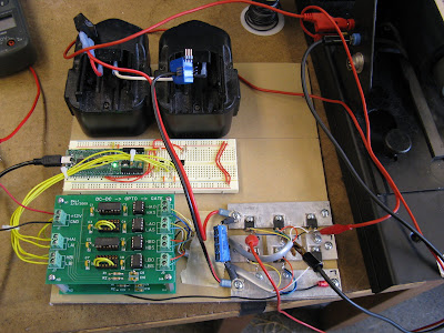 Wait a minute...that looks familiar.
Good thing there are so many other distractions available at the end of the semester. Like finals (lol) and term projects. I'm taking my first ever legitimate electrical engineering course (and actually enjoying it) this year, Introduction to Electric Power Systems, 6.690. It's more focused on grid and transmission topics, but there is a short burst of electric machines (read: MOTERS!) analysis toward the end. So I figured nobody would mind if I squeeze in a term project on motor control, since that's what I seem to do well these days. So, the 3phAC controller is born:
 Wait a minute...that looks familiar.
For those of you who are saying, "Gee, Shane, that looks an awful lot like every other motor controller you've built recently, it's got the same parts and the same hack way of mounting transistor to heat sinks that double as bus bars, and the same controller even," I say, "Of course." (Okay, nobody probably even knows what I'm talking about.) But the point is, there isn't much difference, from a hardware standpoint, between a three-phase inverter and a half-bridge like this one. It's just...three. And since I already have a good, working, modular, scalable hardware solution for this, why not use it?
In any case, the interesting part of AC motor control is the...well, the control. You need to generate three PWMs instead of the usual one. And the values of each need to be updated at the switching frequency (16,000 times a second) to push through a sine table. (Forget doing actual trig on a microcontroller.) So that means a lot of crazy interrupt work. It really does push the Wootstick 1.1, a "special" 16-bit MSP430-based development board, to its limit in terms of event timing.
In any case, it works, and in typical Shane-style I put in a nice Visual Basic interface to show the sensor values for voltage and current, as well as the derived phase angle, which I find interesting but nobody else probably cares about. And most astonishingly, it worked on the first try. It was a scarily easy project, well-planned and done on time. That's right, no MOSFETs were harmed in the making of this project. Video:
Forget all the Course 6 stuff I learned...it just sounds really cool. It's very clean. Just like its bigger cousin (third clip). It can already handle about 1kW, but if you know me, you know it's probably only a matter of time before it gets scaled-up.....
For the full project write-up, click here.
In any case, the interesting part of AC motor control is the...well, the control. You need to generate three PWMs instead of the usual one. And the values of each need to be updated at the switching frequency (16,000 times a second) to push through a sine table. (Forget doing actual trig on a microcontroller.) So that means a lot of crazy interrupt work. It really does push the Wootstick 1.1, a "special" 16-bit MSP430-based development board, to its limit in terms of event timing.
In any case, it works, and in typical Shane-style I put in a nice Visual Basic interface to show the sensor values for voltage and current, as well as the derived phase angle, which I find interesting but nobody else probably cares about. And most astonishingly, it worked on the first try. It was a scarily easy project, well-planned and done on time. That's right, no MOSFETs were harmed in the making of this project. Video:
Forget all the Course 6 stuff I learned...it just sounds really cool. It's very clean. Just like its bigger cousin (third clip). It can already handle about 1kW, but if you know me, you know it's probably only a matter of time before it gets scaled-up.....
For the full project write-up, click here.
Subscribe to:
Posts (Atom)