Tuesday, March 8, 2011

Pneu Scooter: Sensorboard v2

Hrm, all this excitement about snow scooters that don't really work when it turns out that my other electric kick scooter has done a pretty good job this winter. Except it gets really, really dirty:

Ugh.

Especially now that the two-to-three-foot mountains of snow on the side of the road have started to melt, the combination of dirty snow, road salt, and sand has become a bit of a problem. You'd think corrosion or electrical failure would have taken out Pneu Scooter by now. But in fact the only issue I've had is somebody beasting it up and down the hallway so hard that the fuse blew, taking out some critical controller hardware with it. Or some critical controller hardware blew, taking out the fuse with it.

In either case, I essentially had to replace half the active components on the controller, and the IXYS MOSFET brick. One current sensor and all? the gate drivers also ate it. After I rebuilt the controller, things seemed to be working except for one very odd new symptom: For the first 30 seconds or so of riding, one or more of the Hall effect sensors would produce sporadic faults that caused the rotor position estimator to fail and the controller to "click". 

This didn't seem like the microcontroller reset problem that I solved a while back, more like simple sensor faults. My hunch is that the same transient that killed everything else also messed with one or more sensors. And the fact that the problem consistently fixed itself after about 30 seconds of riding a) made me fairly sure it was the type of problem that I couldn't fix using deterministic troubleshooting procedures b) made me not really care. But, in preparation for the Friday Energy Showcase of the MIT Energy Conference, I decided to finally replace the sensors.

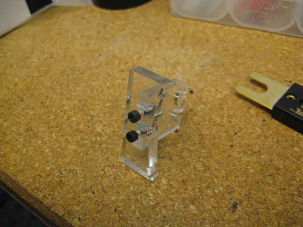
Step one was to laser cut a new sensor mount: 


The original sensor mount was made from polycarbonate and I cut the 2.5"-radius inner surface with a giant boring head in the mill. Lacking the courage and time to attempt this again, I opted for the wimpy solution of just throwing files at the laser cutter. The downside is that the first metallic object large enough to get jammed between the sensors and the wheel may just crack the acrylic right off. But the upside is that I can now put little sensor alignment features right on the part, saving me some careful measuring and gluing.

Also, t-nuts.

+ sensors + wiring + Amazing Goop =


Maybe the sensors will also be more protected from dirt and debris now that they are recessed into the plastic and potted with goop. If not, I can just hit print a few more times on the laser cutter and make a bunch of spares. Replacing individual sensors is virtually impossible, but having entire spare boards seems like a good idea given how fragile the sensors seem to be. I've also switched to the simpler, cheaper, and hopefully more reliable ATS177 Hall effect sensor.

Here's how it fits in with the wheel:


The sense magnet strip has held up pretty well. It definitely needs to be cleaned frequently, because it picks up magnetic dirt and debris off the ground, but overall it's not a bad solution for making a sensored motor without the commitment of internal sensors. As a reminder, the rubber strip magnet I used is McMaster P/N 3651K4. Some day soon I will revisit sensorless control, or hybrid control that only uses sensors at low speed. (3ph v4.0???). But for now, things are at least back to a working state.

Here's Pneu Scooter and RazEr rEVolution at the Energy Showcase:


"Does it generate electricity?"
- No, it consumes it.

"Are you selling them?"
- No.

"Do you have a business strategy?"
- No.

"Is it really saving energy if it replaces walking?"
- No.

"Do you have a card?"
- No.

Wednesday, February 23, 2011

Snow Scooter: 40 hours of work, 15 seconds of fame.


There's the 15 seconds of fame out of the way, now the 40 hours of work:

Last week, it was nearly 60ºF and the Cambridge permafrost and giant piles of snow all melted away. But they were pretty disgusting anyway, by this point. On Friday, I saw that there was a chance of a fresh coating of snow for Monday. And since I don't know what the rest of the spring will bring, I decided I might only have one chance to produce some marginally functional snow scooter. And as you can see from the video, it is exactly that: marginally functional. Or it was, for 15 seconds, until it sucked up a pebble and destroyed the left side motor. Here's how it all went down:

I finished the rear drive module a couple weeks ago, but because of me being an idiot issues with the front meta-bearing, the front drive module was left hanging. Also, the front drive module contains the Victor 883107-7 controller boxes, which needed to be water-resistant. I couldn't use t-nuts, so I had to drill and tap everything. To speed up this process, I marked all the holes in place through their matching clearance holes on other parts. Then, this:


It's actually not too bad when you have a depth setting and can just drill to a mark every time. Blind tapping sucks, but I recently invested in some nice new 4-40 plug and bottoming taps so I felt like I was putting them to good use. One problem is that, even without t-nuts, the tabs and slots still leave gaps, which are exaggerated by the taper of the waterjet. So despite everything, I still needed to seal the inside of the controller boxes with Goop to the best of my abilities:


To the controllers themselves, I added a 1/4" aluminum heat transfer plate to get heat off the bottom copper plane and into the scooter chassis, which is itself cooled by snow. In between the plate and the copper, a thin sheet of silicone thermal transfer pad provides electrical insulation while still conducting heat off the board. The board sits on 1/4" nylon standoffs (also for isolation). Here's the board in place:


I used 14AWG overcooked pasta wire from Hobby King, which turned out to be very necessary since I didn't leave much room at all for the power wiring to squeeze past the edge of the controller board. Only the absurd flexibility of this high-strand-count wire made it possible to get power to the bottom of the board. You can also see the motor wire exit strategy in that picture. Here's a closer look:


The wire runs down the body of the motor, between two of the metabearing bearings, and out of the pulley assembly through a pair of slots in the center rail. Again, only possible thanks to the magic of high-stand-count wire. Wiring the controllers was relatively easy. The controller boxes have Deans connector ports for interfacing to the outside world (battery, motors). Here's the overall layout:


A quick bench test at this point confirmed that both controllers were indeed still operational and that the front metabearing, which I violently bent back into something resembling a circle, was not totally destroyed. That's all the proof I needed to move on to the fun part, which was cutting and splicing the timing belt tank tracks. After calculating the desired track length, I cut the 2" wide timing belt (McMaster 7959K32) into two such lengths and prepared to join them into continuous belts.

One thing I learned accidentally when building my 2.007 robot way back when is that regular old cyanoacrylate (Super Glue) works disturbingly well for bonding rubber belts. I even tried commercial products advertised as rubber adhesives, but CA worked better than those, too. So I didn't bother with other adhesives this time. But in order to make a very strong bond, the CA joint needs to act in shear. This means a lap joint, and the best way I could think of to do this without increasing the maximum belt thickness was as such:


Speaking of my 2.007 robot, I found the missing tank tread and cut it up to make the rubber strips needed for the lap joint:

Poor robot.

One tread dies so that another may live:


These are both about 29.75" in unstretched length. Thanks to the giant compression springs, the pulleys should keep the belts in tension at around 25-50lbf each. I have enough room to remove one more tooth from each belt if necessary, and the tension in that case would be over 50lbf each.

Before final assembly, I made a Y-splitter for both the battery power and the throttle signal, so that one signal controls both motors. One of the goals that had to be dropped in order to meet the snow deadline was differential steering, where each controller gets a separate throttle signal and can drive the motors with different torques. The belts are so close together that I don't know how much net steering torque this would actually contribute, but it's an interesting idea that I want to try at some point. Here are the Y-cables passing through the open space between the two drive modules:


At this point, I was ready to put the belt on. Since the springs together push with upwards of 100lbf, I needed a way to hold them while slipping the belts on from the side:

Large clamp to the rescue.

The belt goes on first, then the front and rear side panels. I also made some quick bogie wheels out of 1" LDPE stock:


These take up much of the normal force on the treads, keeping them from rubbing on the bottom covers of the controller boxes. However, in the video you can see that the pulleys tend to slip a lot. Without the normal force of the tread against the drive pulley, it was hard to get enough torque transmitted. Possible solutions include more tension and sandpaper or other friction coating on the drive pulleys.

And here it is all together:


"Wait a minute. Did you just steal Pneu Scooter's front fork and attach it to snow scooter?!"

Yes. I'll give it back. But it was already snowing at this point so I had to get something on there. It's supposed to be a ski or a ski/wheel combo but for now I thought just a wheel would be fine.

I had some trouble with the belt getting sucked into one side's drive pulley. The problem seemed to be a small offset at the glue joint that was riding up on the rim of the pulley every so often and getting jammed between the pulley and the deck. The solution was to just turn the belt around, so that the small offset would move try to climb the more forgiving inboard pulley rim rather than the sharp outboard rim. If that made no sense...well just trust me.

After that, I borrowed a 19.8V FusionPack from Matthew and went outside...


And, well, you already saw what happened there. I guess the immediate cause of failure was a pebble...


...which got sucked into the thin gap between the tread and the deck, jamming the left side and burning out the (already heavily stressed) motor. The other obvious flaw was the lack of adequate friction between the pulley and the belt, which was not unforeseen and will need to be addressed. With all the weight on the bogie wheels, the pulleys prefer to just slip instead of driving the track. I think this can be easily solved. 

The more fundamental flaw is the debris protection and the fact that the motors are being run with no concern at all for overload conditions. I was sort-of imagining that the snow would cool them off, but the pulleys actually keep snow and water out decently enough that motor heating is now a problem. As for the debris, I just need some kind of brush to keep rocks and stuff out of that gap, I think.

Some parts of the design worked well, though. The metabearings did fine, even the one I mashed on the 20-ton press by accident. Overall, the 540-motor into Banebots gearbox seems to be a good solution, I just need to find the right 540 motor. Perhaps it's time to seriously consider going brushless...

Sunday, February 13, 2011

2.007 / mini4WDbot

Spring semester in MIT Mechanical Engineering means only one thing: 2.007. I'm sure there are other things going on, but this is the only one that matters. (As a TA, I may be biased.) What is 2.007? It's a class called Design and Manufacturing I. It's the original contest-based hands-on mechanical design class at MIT (back when it was numbered 2.70) and it spawned FIRST Robotics, which basically means that a huge fraction of the current and future engineering workforce can trace its roots back to the idea behind this class.

This is certainly true for me - my engineering endeavors started in FIRST when I was in high school. So by the time I got to 2.007, it was familiar territory. If anything, it wasn't challenging enough. I built this:

You can tell it's been neglected. Where is the other tank tread?!

This was back in the days where you got four gearmotors, and four levers on a panel to control them, and that was it. I elected to use only three motors: two for drive and one for the roller on the front that could suck up and spit out the contest balls. The tank treads were basically designed to last 45 seconds, which was, conveniently, the length of each match. This relatively brute-force approach was good enough to place 4th out of 120, mostly because I just learned how to drive it really well. But I don't think it stretched my mechanical or robot-building skills very much.

Part of the problem is that the kit of parts was very crude. Now, kits include a wide selection of servos and gearmotors (that actually work), as well as a user-programmable microcontroller board, so the design space is much bigger. But more than that, I think, was that even though I knew how to play the game and win, I didn't really know how to design at that point.

So how do you design? Well, as one possible data point, here's what the professors in charge of this class have come up with as an example:


This is the "director's cut." The original ending, in which the poor stair-climbing robot never quite worked right, was deemed too sad. But I kinda liked it better, since it is definitely more realistic. If you're setting out on a new design project, keep this in mind:
Failure is always an option. -Adam Savage
So yeah, you start out with the best of intentions and a very clear plan. Even so, you still wind up with a twitchy, shedding pile of parts that can be loosely classified as "robot." I think this is actually a very important learning experience that makes you realize that getting the right answer on every problem set you've ever done in no way prepares you for design. The trick is to learn enough from each failure to do substantially better the next time.

But that's not a very positive message. Design shouldn't be all about failure. It should involve other things, like inspiration and creativity. I contend that my 2.007 robot was neither particularly creative nor inspired. It kinda just was. It was "designed" to accomplish a narrow task efficiently and then fall apart return its borrowed entropy reduction resources to the world (kinda like a FIRST robot...). If you want to see something more interesting, have a look at this:


Now here's a robot that was not particularly good at accomplishing a given task. (And I don't just mean because it was destroyed by reverse polarity the day before the contest, as Charles outlines in his own 2.007 Manifesto, a must-read.) But you could literally spend hours staring at this and still not have seen all the design that went into it. In fact, I probably learned more about building robots by looking at it for 30 minutes than I did in all of 2.007. (Then again, I already started with an understanding of the basics.) 

So I guess that's the inspiration part... If you want to be good at design, go stare at things for hours and really process how and why they are the way they are. Another example of this is Twitch, Jr., which I built after staring at one YouTube video for like two years. For me at least, it's very hard to be creative from scratch. It's much easier to look at something that exists and start manipulating the interesting variables from there. After doing that for a long time, I think, you can generate ideas from scratch.

Anyway, that's all background motivation to explain why it is that I spend so much time working on 2.007 stuff during the Spring (at the expense of some of my own projects, classes, Quals, etc.). This year's game is awesome and the kit is one of the most capable ever. Thanks to some excellent EE work by Max, you can even control your robot with an iPhone now...

So, we have all this cool new stuff and I felt a bit left out with all the "simple cars" running around on the second week of class. Also, I really dislike the continuous rotation servos with cantilevered wheels, which seems to be the default drive option now. (If you know me, you know I'm all about the drivetrain...I don't really care what goes on top of it.) So, I set out to build a more drive-centric minibot base that is (more or less) 2.007 kit legal.


Okay, so you only get at most three gearmotors in the kit. But thanks to the wide aspect ratio, it would drive and turn just fine with just two diagonal wheels driven. BTW, if you want to know how to figure out if your robot will turn, read this. Also you don't get bearings in the kit. But in the interest of demonstrating good engineering practice, I've included them on the outside of the side rails. Also, I wanted to drive it off the roof (the model roof, not the real roof) and have it land upside down and keep driving.

The drive is based on four (or two, if you want to be kit-legal) Vigor BO-P5 40:1 gearmotors. We get these at some huge discount from China and, I must say, I really, really like them. The reason I like them is because they use the most creative planetary gear arrangement I have ever seen. Here's what the inside looks like:

Whaaaaa?

So, something fishy is clearly going on. In general, a two-stage 40:1 planetary gearbox would be hard to produce. Normally, that would take three stages, unless the sun gear was tiny, which it isn't in this case. So what is this? Best I can tell, it is called a differential planetary gearbox. (Not to be confused with a planetary differential.) The ring gear of the second stage is the output, and a difference in the number of teeth between the first and second stage ring gears produces a high reduction ratio in one stage. This bears some resemblance to harmonic-drive gearing, but in nice non-flexy planetary form.

So, the first stage is just a regular planetary reduction, with a 12T sun gear and a 45T ring gear. This gives a first stage reduction of 1+45/12 = 4.75:1. Two sets of 16T planets of different pitches are connected to each other in one planet carrier. The second stage ring is 51T. The ratio of the second stage is 51/6, where 6 = 51-45. Every time the planet carrier goes around once, the 51T second stage ring moves 6 teeth. So, the total ratio is 51/6*(4.75) = 40.375. It works just as well for the higher ratio 120:1 BO-P6 motor, though obviously with different numbers. 120:1 in two stages! Is that not the coolest thing you've ever seen?

Gearbox porn aside, I opted for the 40:1 and 2-5/8" standard servo wheels for a top speed of about 2fps, which is slow in most robot contests but relatively fast for 2.007. I figured it would have a ton of torque and be very controllable, though. Also, there is no other option. These can be hacked to remove the second stage entirely, but a 4.75:1, 20fps robot would not have enough torque to do things like..turn or maybe even move.

I have class at 8AM on Thursday morning, so I decided that I would spend all of Wednesday night building this.


Really, there are only two unique parts that require thought. The side rails are made from kit 1/16"-wall 1"x1" aluminum extrusion. Originally, I designed simple 1/2" wide slots, but then later I realized that, even though there were no interferences in the final state, I couldn't actually assemble it without having wider 7/8" slots where the wheel hubs were. The wheel hubs are made from kit 1" Delrin round stock, turned down and tapped for a 4-40 bolt pattern:


The Delrin hubs fit on the motor shaft and also into the outer bearings...

...like so.

Here's what the robot looks like assembled, circa 3AM:


The base is an 8"x8"x1/4" ABS sheet with rectangular cutouts for the wheels. The motors are face-mounted into the inside of the side rails using 2-56 screws. Amazingly, it is possible to screw the motor on with the wheel and hub in place. The allen wrench fits through the matching hole on the outside of the rail, through small opening in the wheel, just barely past the hub, and to the motor mounting hole.

I assure you this was intentional...

And here it is circa 7AM, wired and ready to go:


It's powered by a cute 7.4V 500mAh LiPo from HobbyKing (kit legal). The controller is...well it's something I don't want to talk about. The motors are driven by four Vigor VS-11 servo guts. The VS-11 is the massive 1/4-scale servo that Twitch uses to brute force its linkages around, and is also 2.007 kit legal. Turns out you can rip the ~2A motor controller out of them and it's still cheaper than anything else you can buy to do the same job.

You might notice it's missing the wheel-mounting screws in the above picture. If I'm to be perfectly honest, I first tried some adhesive solutions but of course they failed miserably and I had to go back and add screws later.

And there you have it, mini4WDbot in under 24 hours. I don't know why I wanted one, but now that I have it I can't stop playing with it. It's just immensely fun to drive. It can drive upside down. It can handle a bit of payload. It can be controlled by radio receivers, a USB gamepad controller, or maybe someday an iPhone. Why have I not built any general utility minibots before?!

Wednesday, February 2, 2011

Snow Scooter: Why don't I have one?


That's what Cambridge looks like right now. We've had a blizzard a week for about the entire month of January, and February started with, oddly enough, more snow. So, there are now 2-3 foot high snow walls bounding every street and sidewalk with another 0-8" of fresh snow/ice/slush depending on the day of the week. The good news is that it probably won't melt until April now, but the bad news is that Quals have set me back about a month on completing the Snow Scooter.

In the last mechanical update from early January, I had just finished all four pulleys and the two drive-side end caps. The gearbox fit nicely in the drive side, but the motor terminals were going to interfere with the end caps on the idler side, so they got a bit of a re-design:


To accommodate the motor terminals and wiring, the idler side end caps are now dished out with a 2" ID. This allows plenty of room for 12-gauge wire soldered to the terminals and routed along the side of the motor to the wire exit slots in the center of the drive module. However, since the end cap wall thickness is now so small, my original plan of pressing a 1/2" steel shaft into the end cap to interface with the side plate bearing was no longer an option. Instead, the 1/2" shaft feature had to be integrated into the end cap:


Nothing too difficult here, since the idler side end cap does not need to transmit torque. (At least, not in any of the Plan A configurations of the Snow Scooter...) Since I had already bored out two disks for these end caps, I had to start from scratch with new stock. Minor setback, but I could think of no other way to clear the longer RS-550 motors. Here's what the rear drive module looks like with the newly-machined idler side end cap in place:

Totally Enclosed, Snow Cooled.

After the initial pulley-making blitz, I switched over to being an EE for a while and designed my own 4-quadrant 50A motor controllers so that I don't have to drop $300 on Victor 883s for this thing. As of the last update, I had only put one together. So, now that Quals are over, I assembled the second one. Since this would not be a Shane Colton project if there weren't some unforeseen motor controller issues, the high side drive on the second controller was dropping out. 

I know from a few years of experience that the HCPL-3120's have a pretty unforgiving UVLO of about 11V. So, I bumped the gate drive supply voltage up to about 14.75V (from 13.5V) and doubled the size of the bootstrap capacitors (to 2μF). This took care of the problem. Since the MITERS electronics bench was fully occupied, I decided to set up a Self-Sufficient Remote Electronics Outpost consisting of my nice soldering iron, 24V/32A power supply, and the immensely useful Sparkfun Pocket DSO.

Is it sad that I own better lab equipment than I have access to anywhere on campus?

The controllers are all set for now, so I turned my attention to assembling, or at least prepping for assembly, the pile of waterjet-cut panels that make up the deck and drive modules. Why, you ask, does one have to prepare waterjet-cut tab and slot panels for assembly? Well, I haven't yet mastered the art of tab/slot/t-nut assemblies yet, so my tabs and slots didn't quite fit together as-cut. Mainly, the tapered edges left by the waterjet make one side of the slot too narrow (or one side of the tab too wide, if you prefer). This can mostly be avoided by offsetting the tab or slot geometry enough to clear even at the narrowest (widest) points. Or, if you happen to own your own waterjet, just fiddling with the toolpath offset itself.

But, as I am but a novice, I just did ideal zero-gap tabs and slots. I also didn't bother so much with t-nuts, since I want some portions of the snow scooter to be waterproof anyway. The drive modules themselves fit together nicely, with just a bit of belt sanding to reduce the width of the tabs enough to fit the tapered slots.


The front drive module is fixed to the deck, while the rear is able to slide forwards and backwards. Two large compression springs will get stuffed in between the two drive modules to keep the belts tensioned. The motor controllers are mounted in the waterproof section of the front drive module, the part hat looks like (and is) a metal box.

Although the side panels fit together with minimal effort, the part that really screwed me over was the long swordfish-looking center panel. Slots with metal on all four sides are much harder to stuff tabs into than ones with only three borders. I knew this would be a problem, and decided that the best way to solve it was with a 20-ton hydraulic press...


...as it turns out, this was not a very good idea. After pressing the center panel into the deck, I realized how stupid it was to do so, given the giant hole through which the motor fits in the front drive module. Pressing on this hole deformed the entire metabearing structure on which the front pulleys run. So, all the careful work I did ensuring a concentric bolt pattern for the mini bearings was pretty much undone. I found that no amount of force applied in any reasonable direction would push the bearings back enough such that the pulley would fit.

That doesn't explain the giant crack. Actually, I did that on purpose. It's a trick I've used before to fix circular bolt patterns that just don't quite line up no matter how hard I try. The idea is that by removing a small strip of material (hopefully somewhere that isn't structural) the remainder of the ring becomes flexible enough to force into place. How exactly this happens is a different story.

So, I think I can salvage the front metabearing. The next step will be a bunch of mill operations for boring out bearing holes and making reliefs for the belt to ensure that it clears the bottom of the deck. Then, final assembly! Now that classes and 2.007 have started up again, progress will be sporadic. But I guess sporadic is better than non-existent, which was the case for the last month. Even if it only lasts for one YouTube video, there will be a snow scooter in the near future.

Wednesday, January 26, 2011

MechE Quails: More Field-Oriented Control

What is a quail? It's like a mixture of quals and fail.

What is a qual? It's like a mixture of...I'm not sure. It's the Mechanical Engineering (Course II) department's bi-annual doctoral qualifying examination. It's a three-day test consisting of:
  • Day 1: Up to three 1-hour written examinations in three subjects of your choosing. Examples: System Dynamics and Control, Machine Elements and System Design, Manufacturing, Thermodynamics and Heat Transfer, Optics. I chose the first three.
  • Day 2: Three 40-minute oral examinations in the same subjects. (20 minutes of reading, 20 minutes of Q&A.) The audience is 3-7 professors in that field.
  • Day 3: A 45 minute presentation on past or present research. (20 minutes of presenting, 25 minutes of Q&A.) Also 3-7 professors in the field of your choosing.
To pass, you must satisfy the professors on at least two of the three subjects, and the research presentation. And you win...well I'm not sure what you win. It's not a dissertation; no degree is awarded at the end of the process. It's more like a mid-term. If you lose, you get a second chance in a few months. If you lose twice, you get kicked out.

This is Try #1 for me. I figure now is the best time to give an honest reaction since I'm done with the testing but haven't yet gotten the results. One reason I thought I would burn a blog post on this is that people tend to Freak The Fuck Out (FTFO) about this test and maybe I can persuade future grad students that it's not really advantageous to do so. The other reason is to try to excuse myself for not doing any work on the snow scooter in the past few weeks. (Not that there hasn't been snow. Cambridge is expecting 8-12" more tonight...)

Anyway, my advice to future quals takers (besides don't FTFO) is to use Try #1 as a test probe. Part of the stress is the uncertainty and mystery of the quals process, which, by the way, is intentionally hyped by both the department and by past test-takers. But they do give you two chances, so you can map the process for yourself and that alone is worth the effort even if you don't pass on the first try. You might, for example, learn that you instantly become stupid on a topic you know well just by walking into a room full of seven controls profs, like I did on the orals. Now if I fail, I know I need to work on that. (Either not becoming instantly stupider, or having the transition still leave me enough phase margin to answer simple questions.)

According to the G.A.M.E. surveys (which were the only things that made me FTFO, briefly) from the past five years, survey responders spent on average 300 hours studying and had, on average, an 80% success rate on their first try. I've never studied 300 hours for anything in my life (including Quals Try #1...and my odds of passing are much lower than 80%) so I can't even really relate to what that means. I would much rather be doing something else. If necessary, would I suck it up and put in the hours on Try #2? Probably. But for Try #1...I don't think so. (Well, as experience shows, clearly not...) Too much other stuff to be working on. Like 2.007, which will have the best game in a loooong time, I promise.

One thing I was mildly excited about was the research presentation. I've been wanting to get feedback from professors (or experts) on my field-oriented control stuff. (Yes, I'm writing about motor control again.) So, against the advice of pretty much everybody, I presented to the controls group. These profs are infamous for tearing people apart, which they did on my oral subject test, and most would not be familiar with me or my work. Kind-of a high-risk strategy, for quals, but I really wanted feedback from that group, even if the feedback is: "Go away." 

So, we'll see how that went. My initial reaction is positive - I didn't get torn apart (that I was aware of...one prof insisted that this has all been done already in the 80's) and I nailed some Technical Triva. In some sense, though, I got very lucky with who was on my panel, but I won't name any specific names. I would say 75% odds of passing, which is much better than my subject tests. I'd put those at about 40%. Any takers? (Is gambling on quals unethical?)

Anyway, the other outcome of all this is that you get yet another exceedingly technical PowerPoint presentation on the modified Synchronous Current Regulator!

Yaaaaay. 70 more where that came from.

(I assume there is no harm in posting a quals presentation...)


This one supersedes my previous PowerPoint on the topic, which is apparently a big hit on Google. It's got more data, this time from Pneu Scooter, better analysis and simulation, and most importantly, much shinier figures. It's all theory, though. If you're interested more in the implementation details, including the controller hardware development, this massive, unedited, neglected, out-dated document is the best I've managed. I promise I will bring it up to date with v3.1 some day soon.

If you're like I was not long ago and have some idea about motor control but not quite enough to jump right in to Field Oriented Control, then you should first check out James Mevey's Awesome Thesis of Awesomeness. Pretty much everything I know about modeling brushless motors and controllers came from that. It's also a review of basically every reference on the topic.

Anyway, that's it for quals...for now. I'll post the results in a comment tomorrow when I find out, for anyone who took me up on those odds... In the meantime I'm going to go design a motor controller.

Monday, January 10, 2011

Victor 883107-7

Okay, so I know I said that one of the best things about building a brushed DC motor-based snow scooter was that for just this once I do not have to design a motor controller for the project...


...well I did anyway.

Honestly, if I had two Victor 883's lying around, I would use those. But I don't, and I'm not spending $300 on something I can make from scratch for less than that. I am done being a slave to IFI/Vex absurd pricing because they have no competition in their power-to-volume ratio. I can stuff MOSFETs into a small space too. In fact, it's what I do in my spare time anyway. The challenge:
  1. Using the same footprint as a Victor 883, make a MOSFET H-bridge controller that can handle 48V and 75A continuous.
  2. Run either on standard RC input or 0-5V analog throttle. Retain isolation between logic and power ground. (The Victors are optically isolated at the signal input.) 
  3. Be less than $140, including board printing and components.
I took my inspiration from this:


The last time I wanted to directly rip off the footprint of an existing MOSFET and make my own cheaper, more easily serviced version was on the Cap Kart. The kart had just finished a week of blowing up giant MOSFET bricks from IXYS and I decided that if it were going to blow things up, they might as well be cheap and user-serviceable. It never blew this one up.

Here is the smaller H-bridge version, which I call the Victor 883107-7:

What's that blue thing?

The name comes from the monster IRFS3107-7 MOSFETs. In the world of MOSFETs, the IRFS3107-7 reigns supreme. If the IRF1405 is a high-end sports car, the IRFS3107-7 is the supercar that shouldn't rightfully exist. It has such massive current handling capability that the D2Pak surface mount package sprouted four extra legs to handle the  source current. Let me put this another way: 0-gauge copper wire, which is the same diameter as this MOSFET, isn't rated for as much current.

Of course the 260A current rating is if you put the drain tab on an infinite heatsink held at a constant 25ºC blah blah blah. It can switch 75A no problem. With two FETs conducting in the H-bridge at any given time, the power dissipation from FET conduction at 75A is: 2*(75A)²*(2.1mΩ)=24W. There are also switching losses, but if I do the gate drive right, the power loss should be dominated by the conduction.

That's still a considerable amount of heat to get off the board. With only one square inch of on-board copper plane for sinking and natural convection, AN-994 suggests a thermal resistance of about 20ºC/W for a D2Pak. Since I'd have two sharing the load and have almost two square inches of copper, this gets split in half. But, my FETs would still be toast at anything above about 50A. (Still, 50A with no external heat sink...)

This is why I opted for bare boards with no soldermask. The heat transfer path is from the MOSFET drain tab to the board top copper layer, through a crapload of vias to the bottom copper layer, through thin silicone padding for isolation, and into an aluminum heat sink.

Heat transfer zone.

Normally, I would then need to worry about keeping the aluminum heat sink cool with some kind of fan. But for the most part my heat sinks are semi-infinite blocks of scooter/go-kart/robot chassis. And, as an added bonus, this one will employ direct 0ºC phase-change cooling (by virtue of being totally covered in snow). Hell, if the road's been salted, I might even try out eutectic cooling...

So I'm confident the 3107-7 won't fail under load, but unlike the Cap Kart's controller, this one has to have on-board logic. And the finally-resolved electrical noise issues of the 3ph 3.1 brushless controller are still fresh in my nightmares. I decided to take the safe way out, importing the completely isolated gate drive solution from the Cap Kart onto this board.

I do still love the IRS21844 gate drivers, but I just don't trust them quite as much as the optically-coupled HCPL-3120 when very high currents are required. It just gives me peace-of-mind to know that my microcontroller and logic are driving the equivalent of four LEDs, and are not in any way electrically connnected to the power circuit.

The original modular, isolated half-bridge from the Cap Kart went a step further by using floating 15V supplies everywhere. The benefit here was that both the gate drive supply and the logic supply were isolated from the power circuit, and from each other. Also, by providing a floating 15V supply for the high side drive, it could be held on at 100% throttle. But, the floating supplies are really freaking expensive. In this newer version, I've opted to use just one floating supply (DCR021205) to isolate the logic's 5V, a trick a stole from the latest 3ph 3.1 upgrade. As for the gate drive, for the first time, I'm trying out bootstrapping with the optocoupled gate drivers:


Diode D4 charges the high side's bootstrap capacitor C6 while the low side is on. Then, when the high side needs to turn on, C6 charges the MOSFET gate while D4 blocks the reverse voltage. This is a pretty common trick for gate drive, and I'm really not sure why I never considered it for the optocoupled gate drivers. The only downside is that you can't get 100% throttle. The low side must be switched on in order for the bootstrap capacitor to recharge. But 95% throttle should be possible.

There's also a bit of a game to play to make sure that the high side gate driver does not go into under voltage lock-out (UVLO). The HCPL's will shut down at 11V. There's a bit of a voltage drop between the high side supply and the bootstrap capacitor because of the Schottky diode. There's also a bit of a drop on the other side because of the voltage drop across the low-side FET. Then, the capacitor loses some voltage as it charges up the MOSFET gate. And finally, it loses some more as it slowly drains through the gate's pull-down resistor. So, forget about using a 12V gate drive supply. 15V is a much better bet. Unfortunately, this means the controller won't run on a 12V battery...oh well.

My favorite thing about the optocoupled gate drive solution is how PWM dead-time is generated. Dead-time is required between turning off one FET and turning on the other. This ensures that two adjacent FETs are not on at the same time, which would short the power supply and cause instant destruction. Here, the optocoupler LEDs are wired in anti-parallel, so that they can't physically be on at the same time. Additionally, an RC filter on the input ensures that it takes some time to switch from 1.5V to -1.5V, turning one LED off and then the other on. The details of how to size the passives for a given dead-time are in the original write-up. Here's what the dead-time looks like in action:


Because these are such massive FETs, they take a good microsecond to turn on and off with 30-ohm gate resistors. I could push harder, since the gate drivers themselves can source/sink as much as 2A peak. But, as I found out in one of my many other controller troubleshooting sessions, slowing down the gate drive a little can sometimes help clean up noise. I chose a capacitor (C10 above) to set the dead-time to 1.5μs, which is what you see above. 

Aside from the fact that I soldered four out of six diodes in backwards the first time, the controller so far seems to work. I've only tested on the bench supply, but it was able to drive about 25A before alligator clips started melting. Once I get it hooked up properly to a battery, I'll be able to really load test it. 

Here's what it looks like side-by-side with a Victor 883:

"But, you said you made yet another controller because you didn't have any Victor 883s."

This one's not mine, okay? I borrowed it for the photo. Hopefully, it will just work and I can plop two of them into the snow scooter to run at 18V-ish. But in general, I'd be glad to have a Victor alternative for other projects as well. If it survives some more abuse testing, I'll post the design files so you can try it out yourself. For now, here's the full schematic:

(Click for full resolution image.)

Oh, and it runs on an Arduino. Did I forget to mention that? My bad.

Wednesday, January 5, 2011

MEMS / Snow Scooter / Panzerkitten / Thing

Cambridge got its first dumping of snow, about two feet of it. And even though it's already mostly melted or trucked away, the pressure's on to create what I call the Micro Electrical-Maniacal Snowmachine, or MEMS for short. (Just so I bait and switch more common search hits like "MIT MEMS"?) Or maybe, as I was thinking yesterday, I should call it Panzerkitten. After all, it is a small, cute, harmless tank tread vehicle.

Thank you, Charles, for the illustration... You can go back to building unnecessarily dangerous and impractical competing vehicles now.

But then again, the seed for this name, "Panzerketten," seems to refer to jewelery that resembles tank tracks, not tank tracks themselves as the literal translation offered by Google would suggest? So it might not actually make any sense. I'll probably just keep calling it "snow scooter" or "the thing" anyway, so it doesn't really matter. If you have a strong opinion, let me know...

Anyway, I got the first batch of waterjet-cut parts for the thing from Big Blue Saw. (I've grown out of the phase where I try to negotiate with the on-campus shop staff about waterjet fees. Plus this way, anyone can make a snow scooter!) For budgetary reasons, I started with just the center plates, which are where all the action happens:


The front (swordfish) plate is like the spine of the scooter, giving the deck some rigidity as well as supporting the front drive module. The drive modules are probably the most interesting part of this build, and I'm trying some new tricks with them to mount the gearmotors inside the track pulleys. To facilitate this, I start with four stainless steel bearings on each side of the center plate:

Pictured: about $40 of stainless hardware. :(

These four bearings form a metabearing on which the pulley itself rides. The pulley is just an aluminum tube with a lip and a metabearing race machined in it on one side. The pulleys are hollow so that the motor and gearbox fit inside them.


Metabearing race.

Copy-paste three more times.


You can really see how the metabearing works in this last picture. The four small bearings ride around in the race cut out on the inside of the pulley, and the result is a lot more space efficient than one giant ring bearing. It only works because the loads are low: the treads get maybe 2/3 of the gross vehicle weight, so maybe 100lbs, and that's spread out across four metabearings on the center plate, four regular bearings on the side plates, and the bogie wheels. The last picture also shows the exit strategy for the two motor leads. The only way to get them out is through slots in the center plate, since there will be spinning pulley and tank tread everywhere else.

The pulleys also get end caps. So far, I've only managed to work out the details of the drive end caps, the ones on the gearbox side. The idler end caps will need to be redesigned to accommodate the longer 550 motors I have planned. As it is, there is virtually no room for wiring. In the mean time, I made two drive caps, complete with 1/2" keyed bore:


They're pressed into the pulleys with Loctite 609, since they transmit torque to the tracks. The small raised edge around the bore is for spacing the pulley out a bit from the side plate's bearing. Both the pulley and the end cap are tapered a little to help keep the track from snagging or trying to jump off. Speaking of tracks, here's where it starts to look real:

What do you normally use 2" wide timing belt for?

I made all these parts while waiting for my Beanbots gearmotors. Beanbots gearboxes occupy a very special place in my mind. On the one hand, they used to make some pretty crappy gearboxes. They lacked proper alignment features, had miserable axial tolerances, tore the shit out of their brass gearteeth, and stripped out the low-carbon output carriers. But this was like...back in 2007. I spent so much time reverse-engineering these gearboxes that I have a spare carrier plate I made out of tool steel on my key chain.

My bad luck charm.

Now, though, they are very well-made. Steel gears, hardened carrier plates, axial spacers, and alignment features other than through-bolts are all standard. Everything is tight, the backlash is minimal, and they run smooth, all for a fraction of what you'd pay for precision planetary gearboxes. Totally legit. It's almost like a totally different company...

...almost.

After I geased my grearboxes, I popped one into the rear center plate to check the fit:


I spec'ed 8-32 bolts to attach the gearbox to the center plate, when in fact the regular gearbox screws are 6-32. But since I had to drill out the tapped holes in the gearbox anyway, that was no big deal. The 8-32s clear everything just fine. With the two pulleys in place, it disappears:


Except for the motor length, there were no clearance issues and it runs smoothly. With the stock RS550 motor, 12V gives 1,000rpm no load at the pulley. That's 9mph at the ground. At 18V, 13mph. The next test will probably be to see how much torque this drive puts out. If it's more than adequate, I can trade back for a little more speed by going to 16:1 gearboxes, changing to a faster 550 motor, or both. If the torque is merely adequate, I'll probably have to live with the 10mph top speed. If the torque is inadequate, well then I'm screwed.

Before I make that call, though, there are more non-trivial tasks to accomplish. The idler pulley end caps need to be redesigned to handle the longer motor. I need a way to join the belt and to make sure I can get it on and off easily. I need the side plates, the ski, and another Razor A3 to sacrifice. And I need controllers. Speaking of which......well this post is too long already so I'll hold off on that.