Sunday, November 17, 2013

tinyKart Black: New peak power and 50m runs.

Now that tinyKart has reached a sort-of mechanical steady state (albeit still with two different motors...), it was finally time to take advantage of the new Kelly KBS48121 controllers with high-speed firmware that should allow it to reach up to 120A peak per side, more than it's ever been capable of before. It certainly felt like it had more acceleration, but I decided to re-quantify it using the two metrics I have from when the original kart iteration was operating a full capacity: 50m standing-start time and total input power.

But first, some new fuses:

Mini ANL (a.k.a. MIDI) fuses!
Up until now, I've used only a single 100A fuse on the battery input side, limiting the battery current using the Kelly controllers. But this restricts the acceleration at high speeds (combination of high motor current and high PWM duty cycle). So I got some of these colorful MIDI fuses with ratings up to 150A. This fuse style, although only rated to 32V, has one of the best current-to-size ratios available for small vehicles. tinyKart's battery is 40V, so I'm pushing their rating a little bit, but I've at least seen them blow before when I reversed a Kelly controller input line and have some confidence that they will clear enough space to not arc over. It's hard to find fuses with intermediate voltage ratings (above automotive voltages, but below line voltages), so these will have to do.

Armed with new fuses, I did a new 50m test. 50m standing-start is a standard I got from the e-Kart competition, an electric go-kart challenge based in France. It's like a 1/4-mile drag race but scaled to a relevant distance for go-karts. Typical times are anywhere from 4-7s. There are some runs at the start of this video that I took when I visited the competition in 2009:


tinyKart has previously done a timed 50m run in 6.5s at the 2012 2.007 EV Section event. Even back then it was reaching top speed (right around 30mph) well before the end of the run. So, the total time is made up of one part constant acceleration and one part constant velocity. The top speed hasn't changed much with tinyKart: Black edition. It might have gained a tiny bit since there's no need to derate the Kelly controllers with high speed firmware. But the batteries and motor back-EMF constant haven't changed. 

So most of the gians are in acceleration. In the previous run, both sides were limited to 80% current in order to keep the KBS36100 non-high-speed Kelly controllers happy. Now with 120A and 100% available (higher PWM frequency, less current ripple, no need to leave a margin), the acceleration is significantly increased, approaching 0.5g with an average-weight driver, I believe. The new 50m time, as a result, is down to 5.95s.

At 0.5g, top speed (assuming 31mph) is reached in 2.83s. So most of the time is spent at cruising speed. This suggests there could be some optimization in terms of gear ratio to improve the time even more, but I don't really care about it other than on a relative scale to see how the new components are doing.

The next test to redo was input power, measured using dual in-line Watt meters. Dual because they are only rated for 130A and I expected to be a bit over that. Also, one for each Kelly controller lets me compare the two motors. (Yes, it also might give a slightly higher than true reading, since they are peak-recording devices and the two sides might not reach peak power at exactly the same time.) Anyway, the test is simple: floor it and see what the peak powers are.

Previously, the highest recorded by tinyKart was 4.1kW during a garage climb run. Now, on level ground, it hit a peak of 4.76kW, with an evenly-matched and dubiously synchronous 2.38kW per side:


It's not proportionally higher based on peak current, but that's probably explained by several factors:
  1. This test was on level ground. The previous one was going up hill. Theoretically it shouldn't matter - current control is current control. But if there is any ramping / slew rate limiting on the throttle (there for sure is) or a mostly-integral current control method (on the Kelly controller), it makes a difference.

  2. Similarly, higher acceleration will cause an integral current controller to be chasing a moving target, so it will never quite reach full current. The faster the acceleration, the more the steady-state error. I have the current control at its fastest setting in the Kelly controller, but it's uncertain how fast that actually is.

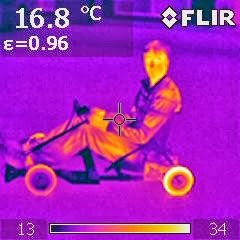
  3. The batteries are starting to show their age. The per-cell internal resistance seems to be at about 10-11mΩ now, compared to 6mΩ for new M1-B cells. One pack (not the one used for this test) also has a particularly bad cell group, as confirmed by the thermal camera:

    Luckily, it's the end cell group, so it should be easy to repair.
    Even the good pack is showing a bit more voltage sag though, which limits the peak power.

  4. As is often the case in Seattle, the ground was a bit damp and leafy. After a few minutes of testing, it became impossible to get any more peak power readings:

I'm pretty sure the previous iteration could not do this quite as dramatically.

4.75kW input should equate to something like 4.15kW output measured at the motor shaft, assuming approximately 100A per motor at peak power and a motor resistance of around 29mΩ. This is ignoring speed-dependent losses, both in the motor and in the belt drive and tires. The actual maximum power reaching the ground leaves could be somewhere in the 3.5-4.0kW range, depending on all those things.

In any case, I'm not one to try cramming even more power into tinyKart. It's already doing more than it was designed for by a good margin, and the power feels perfect for its size and handling. So I will probably just replace the bad cells in the battery pack, prep a second Alien Power Systems motor as a back-up for the EMP, put on the snow tires, and prepare for winter.

Saturday, October 12, 2013

tinyKart Black: Alien Power

Well, shortly after the last test drive, the remaining Turnigy SK6374-170 shed its entire rotor can:

See the gap between the end cap and the rotor can?
I didn't expect this motor to last very long considering the history of tinyKart with these motors. I even remarked in the very first tinyKart build post that they are not the most well-constructed motors. The interface length between the can and the end cap looks to be no more than 2mm. I don't remember if any of the other original SKs failed exactly this way or if their entire rotor assembly shifted axially, but the end result was the same: the rotor can grinds on the face plate.

By this time, though, I had three new motors from Alien Power System ready and waiting. I decided to only replace the broken SK, since the EMP 6374-200 with the custom shaft on the left side drive still seems to be holding up. The Alien Power System 6374-170 is similar to the SK in construction (no can bearing, no radial screws), but since Alien Power System specializes in electric long boards, I was counting on the motors being somewhat more suitable for EV duty.

One other consequence of being a purpose-built EV motor is that the shaft has a nice 3mm keyway for transmitting torque. (RC airplane motors typically transmit torque to a propeller through a hub mounted to the end cap of the rotor.) This means no milling/grinding set screw flats. In fact, no modification is required at all; the motors become drop-in replacements. Of course, now the pulley needs a matching keyway.


I picked up a 3mm keyway broach and 10mm bushing from McMaster for about $60. (It will probably come in handy for other projects as well, as long as I don't lose it like all my other keyway broaches.) The broaching force is low enough that it can be done on a small 1T arbor press. There was just enough material inside the pulley hub to give a full-depth keyway without cutting into the pulley itself, and the broach was able to make it through both hub sides with no problems.


The key interface length is only about 0.5in, but math doesn't lie so it should be able to handle the full torque. Installation was no problem:

Fits the new color scheme as well...
The keyed motor shaft ends about halfway through the pulley, so I'm using a leftover piece of 10mm shaft to span from the other side of the pulley to the outside bearing plate (and a bit further, since I'm too lazy to cut it.) This might offer more radial offset tolerance than the single machined long-shaft with three bearings (two in the motor and one on the outer bearing plate).

The sensor timing was easy, which means there's plenty of magnetic flux available outside the rotor can. (I wonder how much more torque per amp you could get with a steel flux jacket around the entire rotor...) The no-load current seems very good (lack of a large can bearing helps here) and the motor sounds good. There's definitely can resonance, but it's not as sharp of a hollow ringing resonance sound as the SK. So that might bode well for the structural integrity of the rotor at high speeds.

Time for test driving:


Ryan, Dave, and I are apparently too careful to be good test drivers, so I've taken to handing it off to other coworkers (Zack and other-Ryann) who are less emotionally attached to the machine. Other-Ryann, who did the hot lap, is also an experienced racing kart driver, so that helps. Other-Ryann's test laps were done on the following settings:

Left Side EMP 6374-200: 
Current Limit: 75% (90A, 4.3Nm, 43lbf) 
Voltage Limit: 80% (31.7V, 6340rpm, 33.5mph)

Right Side APS 6374-170:
Current Limit: 65% (78A, 4.4Nm, 44lbf)
Voltage Limit: 93% (36.8V, 6260rpm, 33.1mph)

Lacking any telemetry (one thing I do miss from Cap Kart), I don't know how often, if at all, the limits were hit. But after three or four laps at nearly full speed, things still came back relatively cool. Borrowed the FLIR camera from work to see how cool:


Turns out you can rent them at Home Depot as well for about $50, too. And of course if you just need spot measurements, IR temp guns are dirt cheap. (There must be a way to turn one of these into a crude imager with some optics, right?)


It's not surprising, given the way tinyKart drives, that the rear tires came back hottest, about 30ºC above ambient. You can see the Alien Power System motor stayed relatively cool, only about 20ºC above ambient. (Although the stator is where most of the heat is generated, so looking at the rotor only gives a lagging indication of motor temperature.) The belt was only a bit warm as well. The Kelly controller barely seemed to notice that it was being used.

Since it survived other-Ryann's thrashing, I turned up the current on both sides for the next day of testing (backwardly, the first part of the video, with Dave and Zack driving and a shoe cameo by me):

Left Side EMP 6374-200: 
Current Limit: 85% (102A, 4.9Nm, 48lbf) 
Voltage Limit: 80% (31.7V, 6340rpm, 33.5mph)

Right Side APS 6374-170:
Current Limit: 72% (86A, 4.9Nm, 48lbf)
Voltage Limit: 93% (36.8V, 6260rpm, 33.1mph)

This makes it a bit higher torque than tinyKart's ever seen before. Closing in on 100lbf of traction, which is about 0.5g, depending on driver weight (certainly in Zack's case...). After the Friday evening test session things are still holding together. No apparently movement of the rotor can on the Alien Power System motor and the keyway seems to be working well. The EMP motor shaft is also still hanging in there, apparently.

I couldn't really feel much of a difference with the slightly higher torque settings. It could be that the throttle control program running on the Arduino that is taped to the back of the seat is starting to limit the current. There's a filter built in to it to clean up and smooth out the RC car trigger analog input. I'll have to dig into the code and see what the filter settings are. It would also be useful to get some kind of AC current reading on the motors to know if they are actually hitting the Kelly controller current limits.

So far the Alien Power System motor seems like a win. If (when) the custom shaft on the EMP motor breaks, I will install a second Alien motor. At that point, with matched motors and keyed shafts on both sides, and with the high-speed Kelly firmware, the current and torque should be able to go up to 100%...and then we find the next weakest link.

Friday, October 4, 2013

tinyKart Black: Some Nightkarting and 4WD Thought Experimenting

Now that  tinyKart is back in action, I've rediscovered the fun of running it around the parking garage lot late at night when nobody's around. I feel like the new paint job is more fitting for some night karting as well.


New venue, new test drivers: Zack driving, with Mitch providing chase lighting?

It's still running a mismatched motor pair, with an EMP 6374-200rpm/V motor on the left rear drive and a Turnigy SK6374-170rpm/V motor on the right rear drive. I attempted to balance out the torque and speed ratios using the maximum current and speed (voltage) settings in the Kelly controllers, with the left side at 75% current (90A) and 80% speed (32V) and the right side at 60% current (72A) and 93% speed (37V). Not that I think you would feel the mismatch anyway.

One thing that you do notice when poorly matched are the disk brakes. tinyKart has only front wheel braking, so if the braking forces are not well-balanced, it will pull the steering to one side. It was for this reason that we used this recumbent tricycle dual brake lever, which pulls both cables with equal force. Equal cable tension doesn't exactly equate to equal braking force, though, due to different amounts of travel in the brake calipers themselves and different friction in the cable housings. 

So after a half hour or so of trial-and-error tweaking and almost crashing into curbs, the brakes were balanced. When they are working properly, they are quite good. (The 160mm disks might be a bit overkill.) I do want to get the rear drive regenerative braking working too, though; not for more braking force, primarily, but for taking some traction load off the front wheels so they can do a better job of steering into a turn. tinyKart does have a considerable braking understeer, though it's usually complemented by a tiny amount of power-on oversteer, as demonstated in the video above.

I don't plan to leave the kart in its current mismatched-motor state for long. The left motor shaft could suffer the same fate as the former right motor shaft at any moment and the new right motor is transmitting torque through the feeblest of set screw flats at the moment. As a result I haven't been able to use the new Kelly controllers to their full potential yet. Time for a motor upgrade.


These are a new flavor of grapefruit-class motor from Alien Power System. With Leaders Hobby gone and HobbyKing switched over to the 59mm SK3 63xx motors, this is one of the only places I've found that still carries true 63mm outer diameter motors. And for a reasonable price, although still 50% or so more expensive than Leaders Hobby was. They do not have a can bearing, which means they might very well resonate themselves to death at high speeds like tinyKart's original SKs. But beggars can't be choosers. If I found a dodo bird walking around I wouldn't be like, "Damn, it doesn't fly."

They are well-constructed:

Nice double-sided magnet retaining provisions and seemingly good epoxying.
Clean and dense windings with no loose strands.
Total weight is just under 800g and the line-to-line resistance is 29mΩ. All good specs for a 170rpm/V motor. (I haven't confirmed the Kv just yet, but even if it comes up a little higher I would not be disappointed.) And maybe the most interesting feature:

A keyed 10mm shaft!
These motors are purpose-designed for electric long boards, so they provide an actual torque-transmitting feature on the motor shaft: a 3mm keyway! This makes my adventures in custom long-shaft machining and set screw escalation moot, I think. A quick FEA check on the aluminum pulley hub convinced me that even a short 3mm key should be okay for transmitting the full motor torque (6.7Nm at 120A).

Safety factor of about 4.
My mind has trouble accepting this result so I will probably also use the set screws I spent so much time on. But at least I don't need to machine a custom shaft for these motors. I can go back to using a separate idler shaft sticking out of the other side of the pulley to go to the outside bearing plate.

I should be able to get the new motors on and re-time the sensors this weekend. But in the mean time my mind became occupied with an interesting hypothetical test.

4WD Upgrade Feasibility

A long time ago, before the design for tinyKart was underway, I had designed the rear drive modules. (In fact, all the pictures of tinyKart have a prefix of "dm" for drive module instead of "tk" for tinyKart, since the media folder was inherited from this parent project...) The drive module was pretty simple: a motor (almost any face-mountable motor) mounted to a plate, belt drive, a tensioner, and a cantilevered scooter wheel on a custom 17mm aluminum shaft. But back then I didn't design it as a rear drive...I designed it as a steerable drive module for something like a giant Twitch.

Anyway, the drive modules' design got re-purposed for tinyKart's rear wheel drive. But recently I started thinking about whether it could have worked on the front wheels too. The conclusion I came to was, mostly, no. At least, not with disk brakes. The belt drive itself could work, but the brake disks would move to the outside and that would require significantly more structure to mount the caliper.

So, looking for any way to put the drive and brakes on the same side of the wheel, I sketched this up:

Drive Mod v2.0?


Starting from tinyKart's existing front wheel modules, I made only two very minor changes. First, I added a 75-tooth, Module 1, 8mm face-width gear to the brake disk hub. I originally thought of having it replace the hub entirely, but the hub is threaded for interfacing to the wheel rim and it's easier to simply pocket out the gear and fix it on top of the hub:

Pocketing out the gear saves a lot of weight too.
The diameter of this gear is limited by the brake caliper moutning. A gear ratio of 75:18 would match the rear drive pretty well, although there's no reason why they have to match.

Second, I replaced the normal brake caliper mount with an extended brake/motor mount that also holds an intermediate idler gear for achieving frame clearance for the motor.

Shown with the brake disk hidden.
My mind keeps coming up with reasons to dislike this spur-gear design, and then eliminating them almost as quickly. It's a fun game to play:

Spur gears? Really?
Yes. Belt will not fit in the small gap between the disk and the caliper mounting plate. Any other solution would involve lengthening the spindle shaft, which as all sorts of nasty side effects, or a complete redesign. (Either putting drive and brake on opposite sides, or something something even more drastic like a live shaft design.) Chain would work, but  it would be tough to install. Also, I have an deep-set aversion to chain drives after many years in FIRST robotics. I got some inspiration from this drivetrain for an Eco-marathon car I saw in Singapore:


But they are noisy!
Well so are chains and square-wave-drive BLDC controllers.

But the idler gear is stupid and inefficient. It looks like a 2.007 robot drive train.
The efficiency hit is negligible, compared to direct gear drive. It's certainly no worse than a belt drive. Chain might be more efficient but I kinda doubt it.

Such a thin gear can't handle that much torque.
It can, I did the math. Module 1 gears (shown in CAD) are borderline. But for sure Mod 1.5 or an equivalently beefy inch gear with the same face width would work. That's also assuming full motor torque, same as the rear drive. That's certainly not necessary and probably not even desirable, for other considerations such as battery life. A 40/60 or 33/67 front/rear torque split could work just fine.

The motor shaft isn't doubly-supported. It will break, or deflect so much that the gears will go out of mesh.
It does pain me to leave the shaft unsupported, but the maths don't lie:

Safety factor of 2 at 120A torque. Guess where it would break if it did....
Max deflection is 0.02mm.
Safety factor of 2 on the shaft is based on 1020 steel. I don't actually know what the shaft is made of, and the dynamic loading could in theory go higher than 2x static. But I did not model in the gear hub which will spread some of the bending moment closer in to the root of the shaft. And again the front does not need to run 120A torque, see above.

But the idler gear will for sure need to be doubly-supported. It can't have a 10mm steel shaft.
At first I thought the idler gear was safe because the forces on it would be balanced. But this is only true of the separation forces. The torque-transmitting forces actually add up and put even more bending load on this gear's shaft. But, the idler gear could potentially be on a dead shaft that is screwed directly into the mounting plate. So the moment arm will be much smaller than that of the motor shaft. This method would involve putting bearings in the idler gear itself. The details of this are TBD.

What about the aluminum plate? That could bend enough to un-mesh the gears.
True. I state without proof that it can be designed and engineered not to, even if the current CAD placeholder would.

It's impossible to assemble.
It was. There would be no way to put the motor pinion on from the outside. So instead I made a slot in the mounting plate into which the pre-pinioned motor slides. Then, it may take some specially-modified right angle hex wrenches to secure the motor in place. But it's no longer physically impossible.

So yeah, I started out very skeptical of the spur gear drive mod, but now I'm fairly convinced it would work. The appeal is that it can be tested on tinyKart with very little modification. That doesn't mean I'll actually do it - the cost and weight of two more motors and controllers isn't really justified. Also, the power to run the front wheels has to come from somewhere. The choices are either shorter battery life, more battery weight, or less rear wheel power. So for now it remains a thought experiment.

Though it would be an interesting proof of concept for future vehicle projects.........

Tuesday, September 24, 2013

tinyKart Black

tinyKart is back, in black:


The last time I saw tinyKart in one piece was almost a year ago at Maker Faire NY 2012, where it was torn apart in the name of impromptu power wheels racing, including 50 or so rain-soaked endurance laps after it had already lost an entire side worth of drive and brakes in two crashes. To be fair, it was already beat up from a couple years of abuse, off-roading, snow rallying, more snow rallying, and parking garage climbing.

It was certainly not built with this in mind.
I'm actually amazed it lasted as long as it did. It was originally designed as an ultralight go-kart, one that was not a burden to move around and that took advantage of modern electric motor and battery technology instead of loading up on lead, copper, and steel like certain other go-karts. It more than fulfilled its mission in that it was not only as light and portable as envisioned, but also more powerful and fun to drive than we thought it might be given the weight compromises.

If anything, it's weight-saving tradeoffs became secret advantages: chassis flex from the aluminum extrusion frame helps keep all four wheels in contact with the ground; narrow tires match the weight and power to give it a nice, predictable traction envelope. The result was that, somewhat to my surprise, I actually wound up liking the way it drove a lot more than Cap Kart, which was more of a no-nonsense, high-power, infinite traction machine. And unlike Cap Kart, we could take it out whenever we wanted since it serves as its own hand truck.

So I was sad to see it broken and in pieces for so long. Though, it did make it easier to package for shipping to Seattle when I moved out in this direction:

Picture frame box? You mean go-kart box?
Anyway, it's been a long, slow process putting it back together. Mostly because every time I would strip down another layer, I would discover another problem. It essentially came to breaking down the entire kart and rebuilding it from scratch, replacing parts as needed. And since I would have it down to atomic pieces anyway, why not paint it? Except I suck at painting things so pretty much the only color I could pull off would be flat black. Turns out to be a pretty good color anyway.

But first, an assessment of the post-Maker Faire 2012 (and indeed two year sum total) damage that it stared with:
Bent front frame plates, bent front-right spindle shaft, necessitating brake caliper removal.
Bent front frame on the other side. We were originally thinking of leaving these corners off...glad we didn't.
Bent spindle shaft and steering linkage.


As I stripped parts off, I found more and more damage:

Drive pulleys essentially destroyed. One belt had changed itself from a toothed belt to a flat belt with help from a corner of the motor mount.
The set screws had eaten away most of the motor shaft circumference...
This is a good example of the general state of all the hardware.
So in the spring when I first attempted to quickly put the kart back together, I decided instead to take it even more apart:


Every single piece of hardware was removed. Even parts that had come as a whole (the motors) were disassembled to be cleaned and fixed. While I had the kart in a state of maximum entropy and while the weather was nice, I sanded, cleaned, primed, and painted every flat piece of aluminum. That process alone took a week.

Main front frame plates, unbent and sanded to a shiny finish.
Multirotor-assisted drying of special extra-nasty aluminum etching primer.
At this point it's been reduced to a box of parts plus some plates and 80/20 extrusions.
I rebuilt the front half of the kart first, since it had taken the most mechanical damage. Plates were mostly salvaged and the bent spindle shaft was simply refaced, sacrificing a tiny bit of length to recover a flat and perpendicular end surface. The damaged steering linkage was easy enough to replace, and I also took the opportunity to replace the steering thrust bearings and just about every piece of hardware.

A good look at the internal structure of the front half of tinyKart.
Finishing off the sandwich.
Refitting the steering column. The bowl of Rusted Flakes breakfast cereal that is the old hardware.
Half the steering linkage rebuilt, and starting to lay out the rear frame.
Maybe the second-biggest and first-most-futile task of the rebuild was fixing the EMP 6374-200 motors. (I would link to them, but they no longer exist since Leaders Hobby has dissolved and Hobby King/Turnigy has moved on to the less-satisfying SK3 line.) The first step was actually taking the motor apart, no easy task when the shaft is so mangled:


Then, I machined entirely new shafts for the motors out of 1566 carbon steel. I decided to make the shafts long enough to fit entirely through the drive pulley to the second, outrigger bearing. In the previous iteration, a second idler shaft was used on the outside of the drive pulley to complete the structural loop. The planned advantage of the longer shaft was so I could have four total set screw engagement points, two on each side of the pulley, to help torque transfer.

New shafts (left two) vs. old shaft (right).
New shafts also required new drive pulleys. I made them using the same trick of upgrading the hub of a standard Stock Drive Products HTD pulley.


The process involves carefully boring out the stock pulley to be a tight interference fit (0.002" diameter undersized) for the 10mm prop adapters that come with the motors. I luckily happened to find four more prop adapters to use for this round of pulleys. One gets pressed into each side of each pulley, with a healthy dose of Loctite 609 to aid the press fit. The result is a much beefier pulley hub that I modify even more by drilling out the 4mm set screw holes and re-tapping for 10-32 set screws.

New megabeef pulley (left) vs. wimpy old pulley (right).
Original SDP/SI pulley set screw (left) vs. prop adapter set screw (center) vs. my set screw (right).
I hoped that the combination of larger and more set screws would help improve torque transfer and stop the gradual mangling of the drive shaft that happens when you routinely run an RC airplane motor at peak torque into an inertial load. It turned out to be a moot point, which I will get to in just a moment, but first the remainder of the drive module reassembly:

The new shafts were pressed and Loctite 609'ed into the rotor cans. Probably a bad decision, in retrospect.
Anti-giant-prop-shooting-off clip added to the motor. I wish I had considered how little I need this, given the many other ways the shaft is constrained axially.
And two completed long-shaft motors, ready to re-install.
The eccentric roller tensioner is one of my favorite parts of tinyKart.
Back in place with the new pulley. The long shaft passes all the way through the outside bearing now.
I also took this opportunity to upgrade the Kelly controllers from 2x KBS36101 (36V/100A) to 2x KBS48121S (48V/120A) with high-speed firmware. Even though 100A is plenty for this kart, it was hard to achieve that number with the KBS36101 and these motors. My complete guess as to how the Kelly controllers handle current, purely based on experimental evidence, is that they perform average current control but have an additional overcurrent protection at some margin of safety higher than the maximum rated current. The addition protection will cause errors and sometimes controller shutdowns if current peaks exceed the hard-coded current limits. So, to keep the current spikes below these limits, I would have to set the maximum controlled current to about 80% (80A).

The problem is compounded by two factors: Surface permanent magnet brushless motors are about the worst-case scenario for current control, since they have very low resistance and inductance. (Okay, coreless motors are worse.) Small variations in PWM will cause large, quick changes in current. External Hall effect sensors also need to be very carefully timed or they will trip commutation in the wrong place and cause excessive current spikes. Timing the sensors was an arduous task with the KBS36101, but in order to even get to 80% of the rated current without tripping faults it was necessary to be very accurate on the timing.

The new controllers have several advantages that help keep the overcurrent faults under control. They have a bit more current overhead (120A maximum rated current vs. 100A), so if the hard-coded overcurrent fault scales proportionally, so will the controlled current limit I can achieve. But it's also the high-speed firmware version of the controller. Although it's not documented on the Kelly website, the myth is that the high speed firmware also has 32kHz PWM instead of the normal 16kHz. Higher PWM frequency means lower current ripple. If the average current is being controlled, lower current ripple could very well keep the peak currents from tripping the overcurrent limits on these low-inductance motors. Or so my thinking goes...

I left some racing stripes of bare aluminum for heat sinking the new controllers.
And after a bit of sensor timing, the left rear drive is back in action.
To further optimize the sensor timing, I drilled a set of alternate sensor board mounting holes 60edeg ahead of the existing holes:


The sensor boards have slots that allow 60edeg of adjustment already. Rotating the three power wires going to the motor gives a 120edeg shift. So that covers three alternating 60edeg segments of the possible sensor position. To get the other three slices, I had been playing games with reversing sensor and phase wires that I was never quite sure were working. By adding a new set of holes 60edeg offset from the existing holes, I am guaranteed an easy way to find the proper forwarding timing.

Pretty much the only thing from tinyKart that has survived without needing any care at all were the 12S3P A123 B456 26650 battery packs. This is how I found them after a year of sitting on a shelf unattended:

I wouldn't be surprised if that was the exact voltage they were at the day after Maker Faire NY 2012.
After fine-tuning the timing on each side and charging up the battery, it was time for the first tinyKart test drive in almost 12 months:

I think of tinyKart as a nocturnal vehicle, a little bit.
It survived it's first half-torque (60A each side) test drive with no problems, so I decided to go for 75% torque (90A each side) the next day. Then, disaster:


The brand new motor shaft that I machine fractured right at the retaining ring groove after only a few minutes of driving. I don't think the failure was entirely due to the slight increase in torque from the previous implementation of tinyKart. Such a clean break is more likely a brittle fatigue failure caused by misalignment of the inner and outer bearings, now that the single shaft passes through both. There could be other factors as well:
  • The retaining ring groove was deeper than that of the stock shaft.

  • The groove was cut with a rather high SFM. It could have work-hardened the outer layer at the bottom of the groove, which is the most important part for torque transmission.
  • The new shaft material may be harder and more brittle than the stock shaft. It didn't seem that way, but I don't have a hardness tester to confirm.
In any case, it's the first time I've seen a motor shaft fail this way. It broke during some particularly hard cornering, so it could also have to do with shock loading coming back through the belt. This was I think the only time in my life that I was hoping it was a sheared set screw or mangled flat.

All hope was not lost, however. While digging through my box of random motors, I found this:


I left most of my large motors in Massachusetts, but this one somehow made it through to the west coast with me. We bought four of these original SK6374-170's back when tinyKart was nothing more than a CAD model. The other three have been chewed up and spit out by tinyKart already. They are the predecessors to the SK3 line, and are actually 63mm in diameter with a 10mm shaft. They do not have rotor can bearings and the overall build quality is not as good as the EMP motors or the SK3s. But, they are smaller and lighter than the EMPs, they have less drag, and they're a bit more powerful (thanks to an extremely low resistance of 23mΩ line-to-line).

Not expecting it to be a permanent solution, I quickly patched the last of the SKs in to the right rear drive using the old method, an idler shaft to the outside bearing, coupled by the drive pulley itself. This leaves only the two set screw flats for torque transmission, but that's no worse than old tinyKart. Because the motor Kv ratings are different, I set the maximum speeds proportionally in the Kelly software so it would not tend to "pull" at full speed. (I don't think you'd feel it, but the motors would start to fight each other and waste power.)

I'm happy to report that even on mismatched motors and restricted to 75% torque, new tinyKart is every bit as fun as it used to be. Since this is Seattle, initial test driving would not be complete without a little bit of wet surface testing. (I know, I know, the new paint job...it won't last long anyway.) Joining me for testing on the first day of fall, just after an afternoon storm, was none other than Ryan Archer of RC airplane fame, who happened to be in town.

HI RYAN

We both took it relatively easy (read: only a little bit of sliding induced), since the kart is running on one motor that tinyKart's already eaten three of and another with a shaft that's likely to break at any moment. I've preemptively ordered three new motors from a cool site that I just found called Alien Power System. They have a lot of RC stuff that is useful on small EVs, including dual brushless ESCs with reverse. Their 63mm motors don't appear to have can bearings, but beggers can't be choosers in this post-Turnigy-Grapefruit-post-Leaders-Hobby world of 63mm motor scarcity. One thing that do mention is keyed shafts. Not sure if this is optional or included...guess I'll find out. It would be nice to solve the torque transmission problem once and for all.

But for now, tinyKart is running again. I managed to sneak it in just before the end of summer. It performs as well as ever, and is looking way better than it ever has. I'll leave off with some glamour shots of the new paint job before I totally destroy it:

Vertical storage configuraiton takes up very little space at the shop.