Tuesday, November 23, 2010

Pneu Scooter Test Drive Data / 3ph v3.1 / New Project Teaser...

Building your own custom motor controller suuuuuuuuuuuuuucks, but it means I get free wireless data acquisition on my vehicles. I use XBee 2.4GHz transceivers to stream out things like battery voltage, motor current, speed, etc. to a waiting laptop which displays it in real time and/or records it.

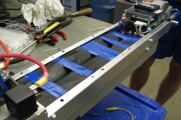
An XBee radio on the 3ph HD.

Even though I made an utter mess of the HD in the last post, the data acquisition works fine. And it's not unbearably cold outside yet, so I wanted to do a short test-drive with the patched-up controller before it's too late. Minor problem: The controller sits inside the aluminum deck Faraday cage and the transmitter range with the on-chip antenna was terrible. This is easily solved by using a little external antenna flap thing that I got from Digi-Key, which attaches to the version of the XBee with U.FL connector and comes up through the back of the deck:


Other minor problem: the receiving program needs to be running on a laptop. This is why I need a fanless netbook, but for now I figured it's cold enough that I can run my laptop, closed, in my backpack, fans pointed upward. (I have an abusive relationship with my laptops...

Mobile wireless link established, and awake during daylight hours for pretty much the first time since returning from Singapore, I went for my first on-campus test-drive:

The Nordschleife, not to be confused with the Ostschleife.


Here's some raw current and speed data from the first 1/3 of this run:

What does it mean?

Raw data is raw, but here are some whole-trip statistics:
  • Trip Distance (measured): 2.1 mi
  • Capacity Used: 1.17 - 1.39 Ah
  • Energy Used: 38.6 - 45.9 Wh
  • Efficiency: 18.6-22.0 Wh/mi
  • Peak Power In: 543 W
  • Peak Power Out: 375 W (est.)
  • Top Speed: 14 mph
These are very nice numbers. The variance in energy use estimate is due to slightly different integrals from the DC current sensors and the AC current sensors. I tend to trust the AC current sensors a bit more, and they're giving a worst-case estimate on par with RazEr's 25Wh/mi, so let's go with that. I won't even bother converting that to mpge because the value is absurd. 

These efficiency numbers give the scooter a best-case range of about 6 miles, though I would expect something more like 4-5 miles for a reasonable SOC range. Not bad for two DeWalt drill batteries. The lithium-polymer pack I had in Singapore (two of these) would have extended the range to about 7-8 miles without adding any weight.

I also did a few more controlled tests. First, a no-load test confirms 1,520rpm at 33V. That's a Kv of 46rpm/V, or a Kt of 0.21Nm/A, right on target. This corresponds to a ground speed of 27mph, but friction and drag will always load down the top speed. I would estimate that the loaded top-speed of this scooter is about 20mph, and I will confirm this when I have mechanical brakes. ;)

I also repeated a test from the early days of my field-oriented control adventures: a launch with and without d-axis/phase control. Here's the original explanation: Part 1 and Part 2. Here's Pneu Scooter without d-axis control:


The controller here can't adjust the phase of the sine waves driving the coils, only their amplitude. As speed increases, the motor's inductance causes current to lag onto the d-axis. To keep a steady q-axis current (torque-producing current at right angles to the rotor flux), it must increase the overall magnitude of the current to accommodate for the lag.

Here's the launch again, with d-axis control on:


Now the phase of the driving sine waves is unlocked, and as the speed increases it is feedback-controlled to keep the d-axis current at zero. In this case, about 17º of phase advance is required at 12mph. The total current magnitude stays steady and equal to the q-axis current. Nothing new here, just more demonstration of the modified synchronous current regulator at work.

Next order of business: Go back and make some of the 3ph HD hacks permanent in a new minor version of the controller, the 3ph 3.1. Here's the board:


It looks...pretty much identical to the last one. I moved the DC/DC converter to the bottom of the board, even though the capacitors technically don't clear vertically. They're only off by about 0.4mm, and I can use some gap-filling silicone padding to space out the MOSFET brick a bit more if necessary. That frees up tons of space for moving the analog RC filters right next to the microcontroller pins and adding a crapload of capacitance everywhere, two things that helped get the HD in working order.

The biggest change is the addition of an isolated 5V logic supply, in the form of a DCR021205. These are similar to the isolated supplies I use on the higher-current controllers to feed the gate drivers, but these convert from 12V to a regulated and isolated 5V. The interesting thing is that the logic can't float arbitrarily: the IRS21844 gate drivers allow only a +/-5V level shift between logic and power ground. And the battery voltage measurement needs some kind of reference, since I'm not using analog isolators. But in theory, no current should flow from power ground to logic ground without going through the DCR02. You can see how I dealt with this problem here:

If you see what I did, shut up.

If this quasi-isolated logic supply doesn't fix the problem, then I would be forced to go back to something more drastic like optically-isolated gate drive. But since the HD is working pretty decently now with just the addition of a 10Ω resistor between logic and power ground, I think this will do the trick. Though I would like to be able to turn the peak current up to about 60A if this cleans up the noise significantly. Look for an update in a few weeks when I get the new boards.

And before I forget, a New Project Teaser for you to guess on:

+7959K32

Thursday, November 18, 2010

Pneu Scooter v1.0: Stealth Mode

I'm back from Singapore and jet-lagged as hell, which means plenty of off-hours work and blog-post-writing.

After three days (nights, whatever) of troubleshooting, Pneu Scooter and the 3ph HD controller have been reunited:


This is the controller configuration for which the scooter was designed, so it fits perfectly under the deck, behind the LiFePO4 battery pack and fuse. In Singapore, I ran into two flavors of trouble with the controller: the current sensor signals were mostly noise and the microcontroller would spontaneously jump out of valid code execution, resulting in a hiccup when the watchdog timer forced a reset. Both were load-dependent phenomena, likely caused by power/signal interference. 

This board isn't as nicely isolated as the higher-power controllers I've built; there are no optocouplers or isolated DC/DC supplies. Everything runs on a common ground, though I did my best to avoid ground loops and keep the power and signal sections as separate as possible. In a later board revision, I will explore some options of explicitly isolating the logic power. For now, though, I broke out the box of capacitors and started adding them wherever I thought some extra filtering might help:


The interesting structure on the left is a row of 10nF ceramic capacitors acting as local filters for the current sensor analog signals. This was the solution I explored in the last post for cleaning up the current signals. It did the trick nicely, and so I'll integrate them onto the next revision of this board. With the current sensors back to a reliable state, I had no trouble implementing the field-oriented current control algorithm that I've come to love. If you missed that part of my life, here's a summary.

Unfortunately, the current sensor fix didn't eliminate the spontaneous resets. These seem to be caused by the processor losing its place in the code. It's not completely shutting down; sometimes the PWM peripheral keeps running in the background. The STM32F103 has a wonderful trick whereby it can tell you what the cause of the most recent reset was (page 109 of 1072 in the FM). Using this, I confirmed that the hiccups are watchdog timer resets, and if it comes down to it, I can actually handle the problem with a clever software fix, as outlined in AN1015.

Fixing a hardware problem in software isn't beneath me, but I first wanted to exhaust all other options. I tried increasing the size and quantity of local bypass capacitors on the signal board. Adding a bunch of 4.7uF ceramic caps to power pins seemed to help, but didn't completely eliminate the problem. I was also only running 20A at the time, and the end goal for this controller and motor is 40A or more peak for hill climbing. To test at higher loads, I added 1mΩ resistors in parallel with the ACS714 current sensors.


These resistors effectively increase the range of the sensor (normally +/-30A) by halving the amount of current that actually flows through it. This is a more compact solution, I find, than using larger current sensors. At 40A drive current, the hiccups came back in full force. I tried other small tricks like setting all unused pins to ground and selectively disabling non-critical features. But nothing seemed to make a significant difference.

The breakthrough was a trick that I learned from...actually I have no idea when or where I learned it. Some time ago, I started naming my ground nets differently to keep them separate in my head and in the schematic. There's the physical connection to the negative battery terminal, which is power ground. Ideally, all of the motor's return current goes this way. There's a gate drive ground, which in many cases is the same as power ground. And there's the logic ground, which should be kept as clean as possible. I connect them all with zero-ohm resistors so that I know they are tied together at one and only one place.


That is...unless there are unintended couplings in ICs or on the board or in free space or whatever. The trick is to quasi-isolate the three grounds by changing the zero-ohm resistors to 10Ω. There's nothing special about this value; it's just the largest resistance that results in less than 1/10W dissipation with 100mA flowing through it. (That's about how much the gate drive and logic draw, most of which goes straight into the XBee transmitter.) The extra bit of resistance, combined with the bypass capacitors on each power supply, creates an RC filter that suppresses high-frequency power transients.

This relatively minor change brought the hiccup frequency down from "every time you throttle past 50%" to "every once in a while at full throttle" at 40A. So, it didn't completely solve the problem but it definitely hints at a path to a complete solution: total isolation of the logic supply. While I explore this option for a board revision, though, the current solution is very ridable. With the sine-wave drive engaged, the scooter is virtually silent. It's actually not unbearably cold yet in Cambridge, so I'll be able to test drive it outside this week and take some performance data. For now, though, here's some video at our favorite indoor vehicle test facility:

Friday, November 12, 2010

Singapore Wrap-Up, Pneu Scooter v1.-1 Test Drive

Wow, somehow an entire month has passed since I started my SUTD visit. Singapore, while incredibly hot and humid every day, is actually a very nice country to stay in for an extended period of time. The food is inexpensive and good, the traffic is light, public transportation is clean and effective, and there are plenty of places to find stuff.

...stuff which inevitably winds up at Gecko Works.

If I am allowed one complaint (besides the one that everyone will have, which is the incessant humidity), I would say I strongly dislike the nature of retail. Namely, shuffling sideways through crowds in the impossibly narrow aisles of a tiny shop trying to find something, and then having to ask how much everything costs (pretty much giving away that I am a foreigner with no likely sense of a fair price). The concept that you can tell me whatever price you want to tell me, and then tell the next person that comes in something completely different, is not appealing at all.

Anyway, my flight out is in eight hours and I'll be returning to Cambridge, MA, where it is the same temperature in F as it is here in C. That means very little in the way of outdoor scooter testing is going to occur for the next few months, so I had to get at least one test ride in while I'm here! There's just one tiny problem - you know, the one that is basically the feeder for 90% of my blog posts - the one that is never really solved: Motor Controller Issues.

I'll get back to those, but as I remind myself that Pneu Scooter is more than just a vehicle for testing one particular controller, I feel obligated to put more emphasis on its completion, minus one custom part. So I will designate this the build summary and maiden voyage of Pneu Scooter Version 1.-1:


The principle new technology for me in this project was a new flavor of custom-made miniature hub motor built into the side of a pneumatic wheel, which will provide a much more cushy ride than the 80A urethane bricks on BWD or even a normal Razor scooter wheel. The trick is avoiding the valve stem, since miniature hub motors need every millimeter of radius they can get to produce sufficient torque. The solution here, which comes with the added benefit of minimal wheel modification, is to simply offset the hub motor onto the side opposite the valve stem.

Like so.

Ok, so it's not as elegant and compact as the ultra-miniature hub motor from RazEr, but it's easy to make and the ride is wonderful. And it uses up the leftover custom stator laminations laser-cut by Proto Laminations for BWD. And, I got to try out a new technique that I've been ranting about for a while: making the can out of stacked waterjet-cut plates with magnet-aligning grooves. I classify that as a total win, especially for thin-profile motors where only a few plates are necessary.

I also got a chance to cancel some of the bad juju of BWD's handlebar mount with a much beefier front-end solution:

In total I used about 6" of my 20' of aluminum.

Here's the fully-assembled vehicle right out front of Gecko Works:


I like the simple, square look and the fact that it is stealthy enough to pass for a regular Razor scoo-wait what the fuck is that lump on the back of the deck?

Laaaaaaaaaaame.

Yes, it's one of those cheesy electric bike controllers that I found in plastic bags at the e-bike store. Yes, it's lame and noisy. (You can hear it buzzing away in the video, occasionally drowned out by the crane-mounted jackhammer that's been demolishing half of Singapore for the last week or so.) Yes, it totally ruins the stealthy look of the scooter. Yes, I should be capable of producing a working brushless motor controller by now. Yes, I am a failure.

Actually, I did manage to do a lot of independent troubleshooting by moving the 3ph HD controller over to an electric bike. Decoupling the electrical and mechanical tasks was a good idea, since it allowed me to finish the scooter mechanicals while simultaneously testing the controller on a known-to-be-functional vehicle. What I discovered were two (possibly related) problems that I need to solve:
  1. The current sensors readings are garbage. The DC sensor reading is clean, but totally incorrect. The two phase current sensors are just noise. Well, not just noise, but I'll get to that. Since I rely on the current sensors for field-oriented control, this is generally bad.
  2. The microcontroller will occasionally jump out of valid code and/or lock up, forcing a watchdog timer reset. This results in a momentary loss of torque. It's definitely load-dependent, meaning it could very well be caused by some kind of induced noise from the power side. (As a side note, I found a great reference in ST Application Note AN1015 on how to make EMC-robust software.)
One thing we don't have at Gecko Works is an oscilloscope. So, getting a clean picture of the current sensor signals noise was not an option. But, I generally suspected PWM-induced noise, and after taking a look at the sensor data, I remembered a trick I learned from this Prof in 2.671, the only undergraduate class with notes that, time and time again, I actually find myself going back to use. The clue was that the sensor data, with the wheel locked so that all current should be DC, still appeared to be periodic:


It looks as though the current is oscillating at exactly 5Hz. However, nothing at all in the system is happening at 5Hz, so this doesn't make sense. And random white noise would not show up as neatly periodic. The trick is that it's actually aliasing of a higher frequency noise source, namely the PWM. I was 99% sure of this because of the details: The data is transmitted at a frequency of 20Hz. Nyquist says that the highest frequency you can record at 20Hz is 10Hz. 20Hz will look like 0Hz (this make sense). 11Hz will look like 9Hz (this requires a bit more thought). 15Hz will look like 5Hz. In fact, (10n+5)Hz for any integer n will look like 5Hz. The PWM frequency is 15,625Hz. Since the PWM and the data transmission are created from the same clock source, it makes total sense that the PWM noise appears as an aliased signal in the current sensors.

The extra 1% of certainty: By changing the PWM frequency to 15,564Hz I can test this theory. Sure enough:


It's a little harder to see, since 4 doesn't go evenly into 10, but the period is now 4Hz, which is what 15,564Hz should fold down to, given a 20Hz sample rate. Case closed, it's PWM noise. Who needs an oscilloscope?!

After spending about 10 seconds looking at the board schematic and layout, I realized why my current sensor signals are mostly noise. I included an RC filter at the output of each sensor, but with R=10kΩ and C=1.5nF, it ain't filtering 16kHz. I honestly have no idea why I chose 1.5nF...it very well could have been a typo. The other, possibly larger problem (since the motor's own inductance should filter the current a great deal more than is reflected in the data) is where I put the capacitors. In power circuits, where you put things is probably even more important than what you put. In this case, I put the capacitors near to the current sensors, leaving a long stretch of high-impedance trace antenna going right under the MOSFETs:


I'll have to fix this in a later board revision. For now, adding (properly sized) capacitors right at the STM32 breakout pins seems to do the trick. A 10nF at the pin reading the Phase C current sensor revealed a beautiful and accurate current signal behind all that noise:


So for now, I should be able to solder some capacitor sculptures onto this board to make it work. That may not be the end of the troubleshooting, but at least it will be one large part taken care of. It'll be much easier to proceed when I can trust the sensor data. 

Ah, more electrical troubleshooting. Something to look forward to when I get back... :-/

Saturday, November 6, 2010

Gecko Works, Stuff@SG, Pneu Scooter MechE

I'm just about at week 3.14 of my visit to SUTD, where one of my tasks is to help set up an interim interim workshop. The interim campus, with its Pappalardo Lab-sized fabrication facility, won't be open until April. In the mean time, we are in a workshop known as "the shed". No, seriously. Since "the shed" is not a very inspiring workshop name, we've renamed it Gecko Works. (Because the surrounding area has an abundance of geckos. And not the friendly type that try to sell you car insurance. More like the type that jump out of the toilet when you flush it.)

As of last post, Gecko Works was pretty empty. Since then, workbenches and about half of the tools have arrived. A virtual Gecko Tour:

Welcome to the SUTD interim interim shop facility.

 Here is a sample of the workbenches. This one is patiently awaiting welders.

The "What the fuck is all that noise?" table. 

 Cuttin', drillin', tappin'.

Baby arbor press is very cute. Perfect for baby wheels.

At this point, we're just lacking the Heavy Machinery: MIG and TIG welders, benchtop CNC mill and lathe. Odds of it arriving before we leave: slim. Oh well. At least we got the basics laid out. There's also a 3D printer, though it hasn't been moved down from the main SUTD offices yet. Hopefully, this will be more than just a six-month temporary shop. The goal is that it will be a prototype for a "fabrication cell" that can be copy-pasted into the interim and final campus. It's small enough that each team in a project-based class could get their own cell in which to work and store their hardware.

My in-between-other-things task has been to go around the country (it's not that big) looking for good places to buy commonly-needed engineering supplies. For anyone who happens to be in Singapore looking for stuff, here's a running list of places I've found to be convenient and legitimate sources of the types of stuff I typically need: Stuff@SG. My only warning: Do not go to Sim Lim Square.

Don't go here.

Go to Sim Lim Tower:

Go here.

They are not the same thing. Sim Lim Square is like if you took Radio Shack and made it six floors. Six floors of bullshit consumer electronics stores with two electrical supply stores hidden on floors 2 and 6. (If you expand Radio Shack to six floors, these would be analogous to the poorly-stocked bins of resistors.) But if you didn't know that Sim Lim Tower exists right across the street, and is full of real electrical hardware stores, you could easily be fooled into thinking that Sim Lim Square is the right place. Not saying that happened to me......just be warned.

Supply chain in place and tools at the ready, I decided to spend Saturday pretending that I'm a MechE for once instead of working on motor controllers. To make sure I don't revert to EE ways (and to keep the aluminum chips out of it), I moved my controller off of Pneu Scooter and onto the first official SUTD electric vehicle:

Who says electric bikes are dorky?

It's got a 36V, 46-pole (O_o) hub motor that I can use for independently beating the software bugs out of this damn controller, or blowing it up. I'd be happy with either outcome. But more on that in a later post. While I have unFETtered access to Pneu Scooter, it's time to face an old demon: mounting a Razor scooter handlebar rigidly to a custom deck. BWD had serious problems because it had only thin sheet metal flanges for mounting stuff. Even with the equivalent of a two-piece clamp holding the front together, it still makes creaky noises when you step on it and the handlebar never quite returns to the same place when you fold it up. Clearly this experience calls for a degree of overcompensation on Pneu Scooter.

METAL.

From the 20 feet of 5"x1/4" aluminum I bought, this is what I needed. Ten 4-40 screws into the 0.26" side walls of the u-channel should do the trick. A few more in the front may also come later, depending on how thoroughly I feel like erasing the impending failure-feeling associated with BWD's handlebar mount from my subconscious. Mounting provisions taken care of, I couldn't resist taking it for a quick unpowered spin in the parking lot, so I put the Razor handlebar on with the original wheel:

Odd...

It looks silly, but it coasts nicely enough. Only the slightest bit of noticeable drag from the motor at normal kick speeds. This is good, because if the controller fails or the battery runs out, it's nice to be able to unplug it and kick your way back home.

The last piece of the puzzle is the front fork. I thought this would be moderately difficult to modify. Not so. The Razor A3 comes with a shock-absorbing hinged front fork, as opposed to the welded solid Razor Spark front fork we used on BWD. This one comes apart with one screw, leaving two nice mounting surfaces for a custom job:


The normal fork fits flush to the inside surface of those flanges. Turns out if I instead fit a custom fork to the outside surfaces, the width is perfect for clearing the 6"x1.25" pneumatic wheels. I whipped up the necessary plate geometries out of some more of my infinite 1/4" bar stock.


It's still missing the spacer that bumps up against the rubber shock absorber. And yes, it is being held together with drill bits. I don't have the proper screws and will have to make a trip to Homely Hardware on Monday so I can finish this off. But aside from that, there are no obstacles remaining in the mechanical path to completion. Which means I'll be back working on software or something soon...


Monday, November 1, 2010

Pneu Scooter: Singapore Edition

Sorry for the cliffhanger ending to the Can I Finish Pneu Scooter in Three Weeks quintilogy. The truth is, I probably never had a chance, but if I didn't try then I wouldn't have made any progress until basically winter break. Instead, I got most of it done and decided at the last minute to stuff the whole thing into my suitcase (which was still only 47lbs) and take it to Singapore.

Oh yeah, I'm in Singapore!

I'm here on a month-long visit to the Singapore University of Technology and Design (Established in collaboration with MIT). If you're familiar with Singapore's universities...well, you've probably still never heard of SUTD. It's a brand new endeavor; an attempt to build a university focused on design, in a broad sense. The first entering freshman class will be in 2012, at an interim campus until the shiny new campus near the airport is completed. For now, though, we're at the interim interim campus, the third and fourth floor of a primary school.

I'm actually staying at NUS, since SUTD doesn't have any student housing yet. One of the first things we did was check out the NUS electric vehicle workshop:


The frame in the foreground is a work-in-progress three-wheel, two-seat, road-worthy electric vehicle. The two bubbly-looking cars in the background competed in the Shell Eco-marathon, and the one on the left (I think) won the Asia competition in Kuala Lumpur.

I should warn you that I am the worst tourist ever. Most of my pictures are of workshops, parts, stores, aluminum, or some combination of those nouns, such as "aluminum stores." Here is my one and only touristy picture from the entire trip so far:

And it's not even a good picture.

I mentioned that the SUTD interim interim campus is the third and fourth floor of a primary school. For obvious safety reasons, primary schools don't have fabrication equipment, so one of our tasks here is to create an interim interim shop. That is, a prototype of a "fabrication cell," a more-or-less self-contained design and fabrication space with modern rapid prototyping tools as well as the standard set of hand and power tools. The space in question was introduced to us as "the shed," which I thought was a little odd.

Oh, now I get it.

The shed, or as I've started calling it, Gecko Works, is a great place to escape from the faculty offices and actually do some hands-on work. Or at least, it will be, once we stock it with the essential machine tools. For now, it at least has tables, desks, an assortment of hand tools, and most importantly, air-con. In the weeks to come, we will be setting up a benchtop CNC mill and lathe, MIG and TIG welders, a drill press, horizontal and vertical bandsaws, grinders and sanders, and various other small tools. This is my first experience with actually outfitting a shop space from scratch, so I'm having fun.

Shop space is one component of making stuff. Another is parts (and raw materials). I figured the best way to get motivated to find parts and raw materials sources in Singapore would be to intentionally leave a few of the critical pieces I would need to finish Pneu Scooter in Cambridge. Actually, I just forgot a lot of stuff. So, some of the last two weeks has been spent tracking down good places to get stuff.

First of all, Hobby King still works in Singapore. In fact, it might work better, since much of their shipments pass through Singapore anyway on their way to the US. This takes care of things like radios, brushless motors, ESCs, wire, and of course, cheap lithium-polymer batteries. It was those that I was particularly after, since airline regulations (justifiably) prohibit me from traveling with homemade lithium-ion battery packs. So, I ordered up some of the "long" Turnigy batteries that I've been eying for scooter use ever since they were released.


At 111Wh (22.2V @ 5Ah) and $51.26 each, these batteries represent one of the best values on the market ($462/kWh). If only lithium polymer didn't have such dramatic failure modes, I would totally use these for everything. And they fit so nicely into Pneu Scooter's battery bay. Maybe some day I will overcome my fear of fiery death and use these permanently.

I also neglected to bring any polarized connectors with me, but luckily Singapore has at least two serious RC hobby stores, Rotor Hobby and Singapore Hobby Supplies. Don't expect Hobby King-like deals, though; the prices are on-par with what you would pay at a hobby store in the US (i.e. really freaking overpriced).

During my random scouting, I also stumbled upon an electric bike store. Since Singapore is closer to the source of mysterious Chinese brushless e-bike controllers, I should not have been surprised to find some in little baggies here:

I almost don't want to know what's inside.

In the same general area, I also found a very good, if oddly-named, hardware store:


And there's the (in)famous Sim Lim Square electronics tower, full of pushy salespeople trying to sell you mobile phones. It's kinda like a really big Radio Shack. Buried in there, though, are some decent electronics supply shops, where I was able to get soldering equipment, connectors, etc.

In fact, the only thing that I find sorely, horribly, frustratingly missing is a place to buy raw freaking material in small quantities. We are so totally spoiled by McMaster-Carr and Online Metals in the US that I haven't ever really considered where I would go to find aluminum chunks elsewhere. The concept of web stores in general is lacking here. Mostly, you go to a tiny shop with aisles just big enough to shuffle sideways through and annoy the owner until you get what you want. I actually found a shop like this specifically for aluminum:

It was closed...

I was seeking some 1/4" thick plate from which to make the part of Pneu Scooter that attaches the Razor scooter neck to the custom deck. You know, the bane of BWD. I wanted serious overkill plate stock this time, instead of sheet metal. I went back to Teck Cheong Aluminum during business hours to find that they would only sell aluminum in standard-length stock, i.e. 20-foot bars. So, I did what any reasonable person would do...

I accidentally the whole aluminum bar.

Pound for pound (all 30 of them), it's actually a very reasonable deal @ $1.81/lb. Compare this to the nearest product at Online Metals ($3.25/lb) or McMaster ($6.42/lb). Only, you have to buy enough aluminum to last through the next two zombie apocalypses. Oh well.

Back to Pneu Scooter.

Before I get to finishing the front fork and building my aluminum fortress, though, there were some lingering controller issues to be worked out. And even before that, some battery wiring. I decided to try something new: a precharging circuit for the controller. I am a bit tired of arc eroding my connectors (BWD's first connector had almost no metal left when I replaced it). The problem is that extremely high discharge 10-12S battery packs and oversized bus capacitors on the controller lead to major inrush current. There are all sorts of tricks for limiting inrush current, but precharging the capacitors through a resistor is one I'm familiar with from the Cap Kart.

Rather than putting a bulky contactor on the scooter, I opted for a two-connector system. They share the same positive lead, but one has a negative lead which passes through a 47Ω power resistor:

The precharge resistor.

The resistor is sized so that the precharge circuit can actually power-up the logic stuff (microcontroller, XBee radio) but it would have an unpleasant time trying to drive the motor. I found a wonderful back-to-back configuration for the Deans connectors that made wiring very simple, which you can see on the right-hand side of this photo with the controller, fuse, and precharge circuit:


The order of operations for power-up would be to plug in the precharge connector, followed shortly by the main connector. It's not necessarily user-friendly, but it will limit progressive connector destruction. In the process of wiring everything up, I came up with a simple plan for waterproofing which will probably have to wait until I'm back in Cambridge. 

Here's the part where I complain about motor controllers and how they are impossibly frustrating to build and how I should just buy one, and then realize that the ones I could buy for a reasonable price all suck in one way or another and that I am simply doomed to troubleshooting my hardware because it's still ultimately more effective. (Sound familiar? I went through the same cycle with BWD's 3ph Duo, which ultimately became a fairly reliable controller. I probably just need to stop complaining and accept the fact that hardware will cut you.)

The problem I was having back in Cambridge was that the program on the STM32 chip would spontaneously stop running, but the PWM peripheral would keep going with its last state. This is particularly bad for a brushless motor, since it just locks the drive up. At speed, this would be disastrous for both human and hardware. To take care of the safety aspect, I added a watchdog timer that resets everything if the control loop fails to run. This doesn't really address the root of the problem, just the symptom. 

As it turns out, much of the problem went away simply by actually setting the Hall effect sensor timing properly. (It was left in a state of "close enough" before, which was actually almost 45º off.) I still don't think this solves the problem, but it does point to possible avenues of further exploration. Is it sensor glitching? Is it the speed estimator? Do I need to add some more error handling? All possibilities. For now, it at least runs up to full speed and survives the less-frequent watchdog resets without destroying itself:

MIT Tech TV

The motor itself seems quite capable and efficient. At 33V, 100% throttle, with the timing set correctly for sinusoidal commutation, it only draws 1A no-load. Also, the external Hall effect sensors seem to be doing their job quite nicely, despite the imprecisely-cut magnet strips. In general, the subsystems all seem to be working well. 

I'm hoping the remaining problems are pure software, and not some horrible hardware-triggered software glitch. Even so, it'll take a few more controller tests and tweaks before I'm confident enough to road test it.  But, I do plan to keep working on it a bit here for the simple reason that, unlike Cambridge in November, it's hot here and I can actually ride it outside....maybe.