In its original design, TinyCross used four identical Alien Power System 6374 170rpm/V brushless motors. But with the weight distribution being heavily biased to the rear, it really makes more sense to use larger motors there. I had seen some examples of electric power steering motors that might be suitable, so I did some eBay exploration to see what was available. I settled on a Hyundai part (56300F2200) that looked common enough that I could always find spares:
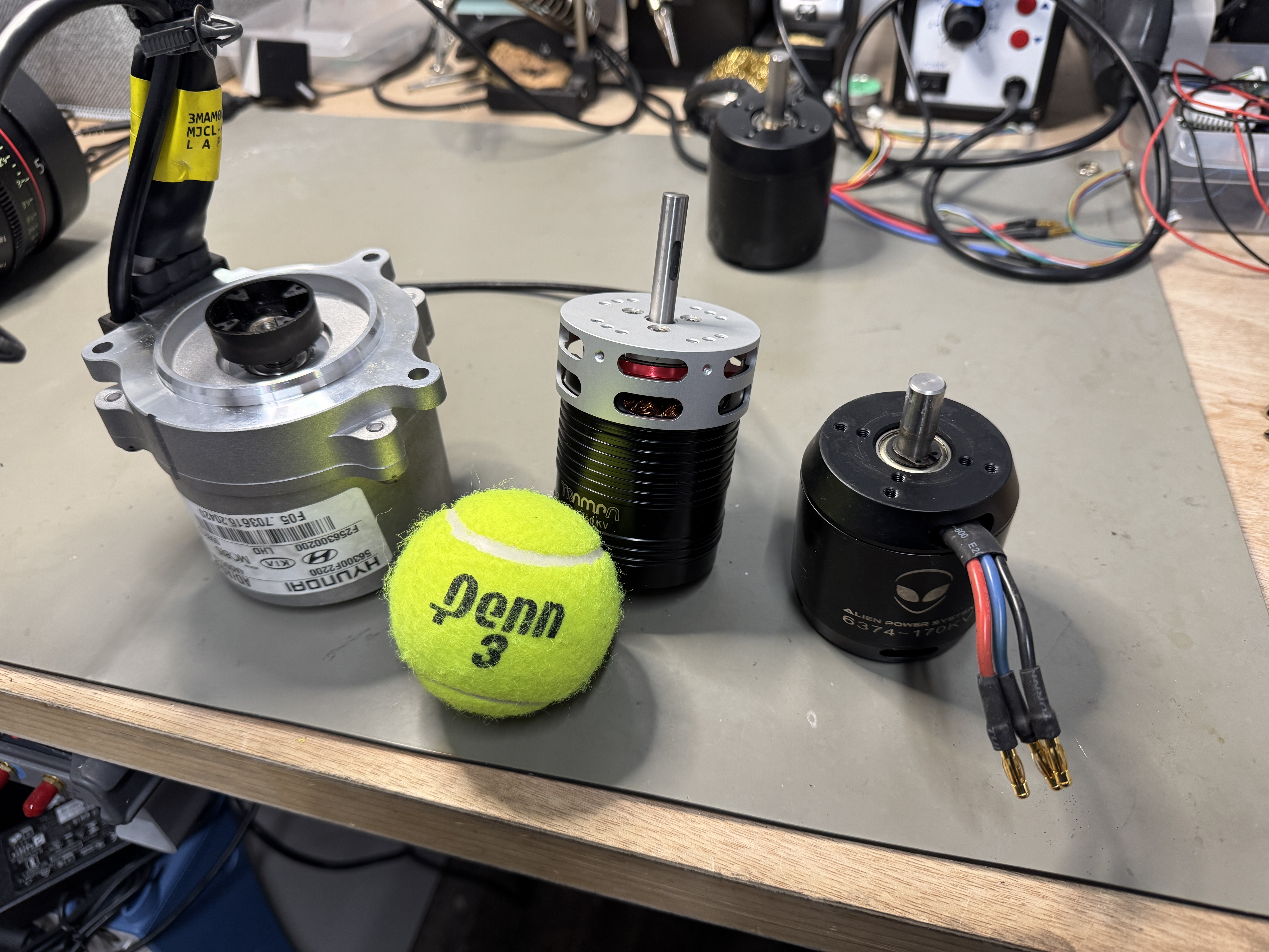 |
| Hyundai EPS Motor (left), Trampa 6376 (middle), APS 6374 (right) |
I was surprised to find that the torque constant (and thus rpm/V) of the Hyundai EPS motor was actually very similar to the APS 6374 170KV, meaning it could just drop into the design with the same gear ratio. The main difference is that the EPS motor is a 6-pole inrunner instead of a 14-pole outrunner. This makes it easier to get heat off of the stator winding. The resistance is also much lower, and the wire gauge going in suggests it can probably handle even more than the 100A peak I've been running in the rear. But the extra performance overhead comes at a price...it's big!
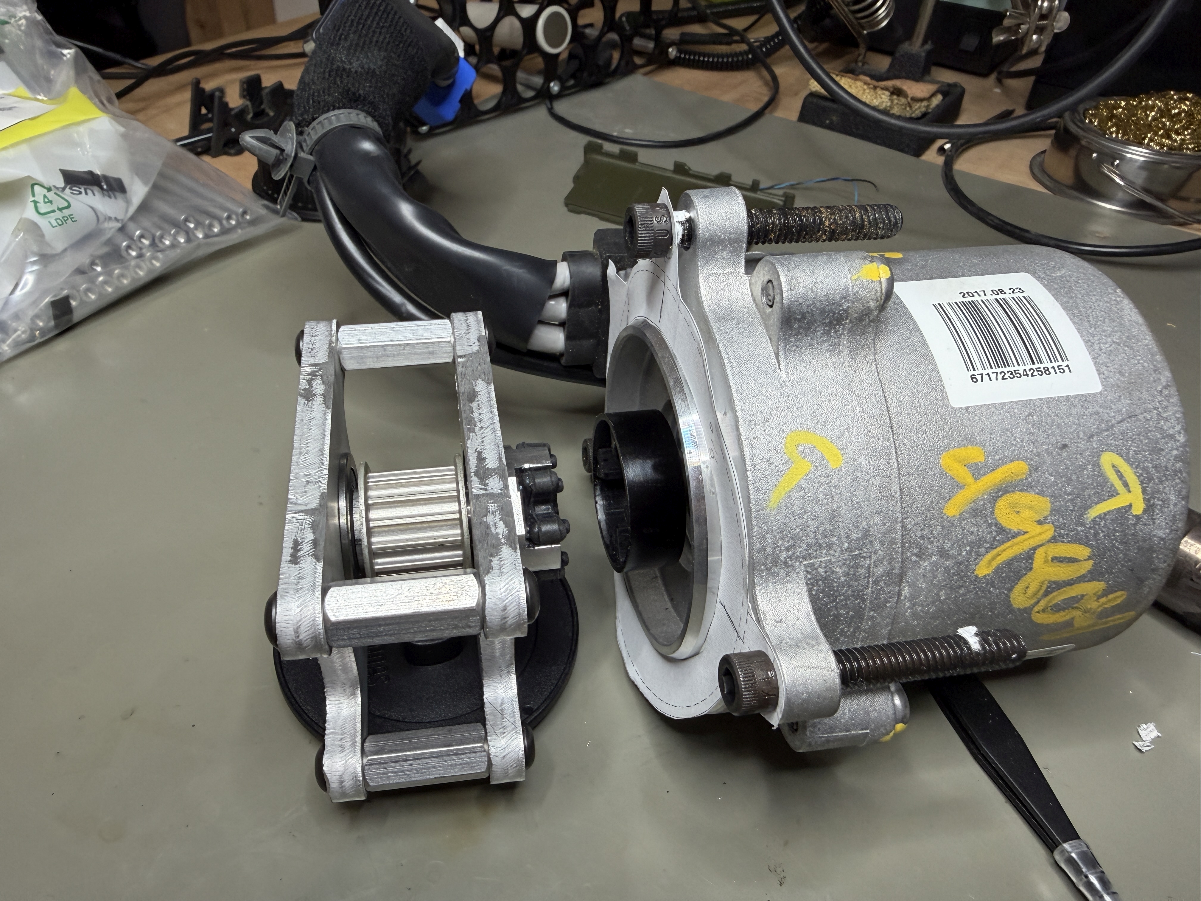
Although this motor is relatively small in the context of automotive electric power steering, it's still a lot larger than the APS 6374. It weighs almost 2kg with the wire harness still attached, compared to 0.68kg for the APS. It also has a diameter of 88mm and a bolt circle of 109mm, so it would be a tight fit into a drive quadrant designed for a 63mm outrunner with a face mount. The hardest part, though, would be adapting the coupler to TinyCross's drive pulley without increasing the width of the existing design. The original shaft adapter for the APS 6374 used a clamp and key to secure the drive pulley to the 10mm motor shaft:
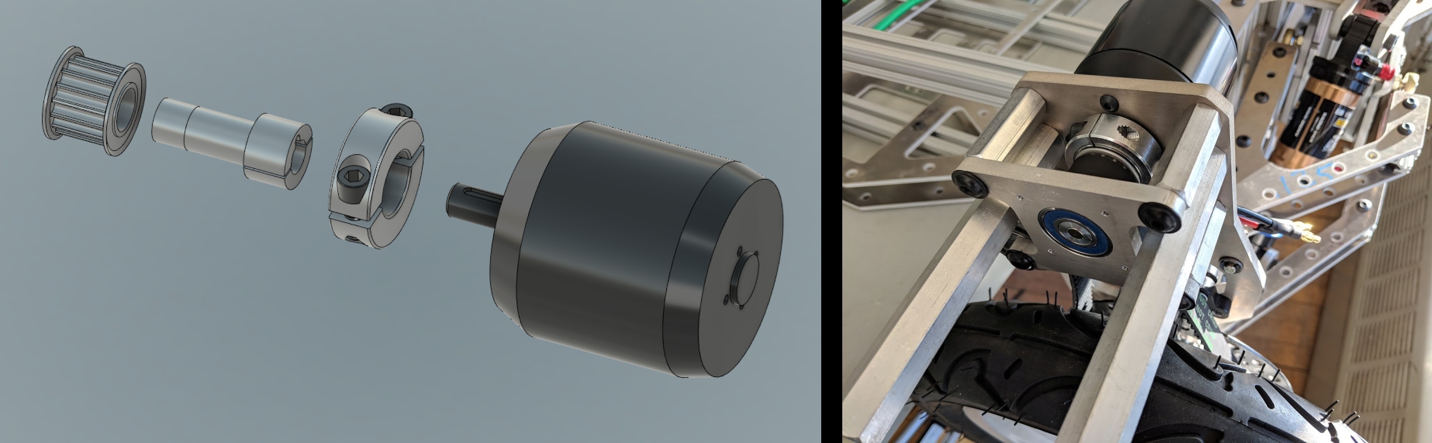
But the Hyundai EPS motor has a large plastic coupling-half pressed onto a short spline shaft, intended to interface to a mating part with a flexible rubber coupler. So, unlike the old design, the drive shaft can't use the motor's bearing as one of its supports. I would need to add both another bearing and the mating coupling-half to the pulley shaft, without changing the belt location.
I played with this in CAD for a while and determined that it would probably require moving the motor mounting plane inboard to make more room for the new drive shaft. That was more work than I wanted to do at the time, so I put the project aside for a few months. But luckily when I came back to it, I drew up this evil thing instead:
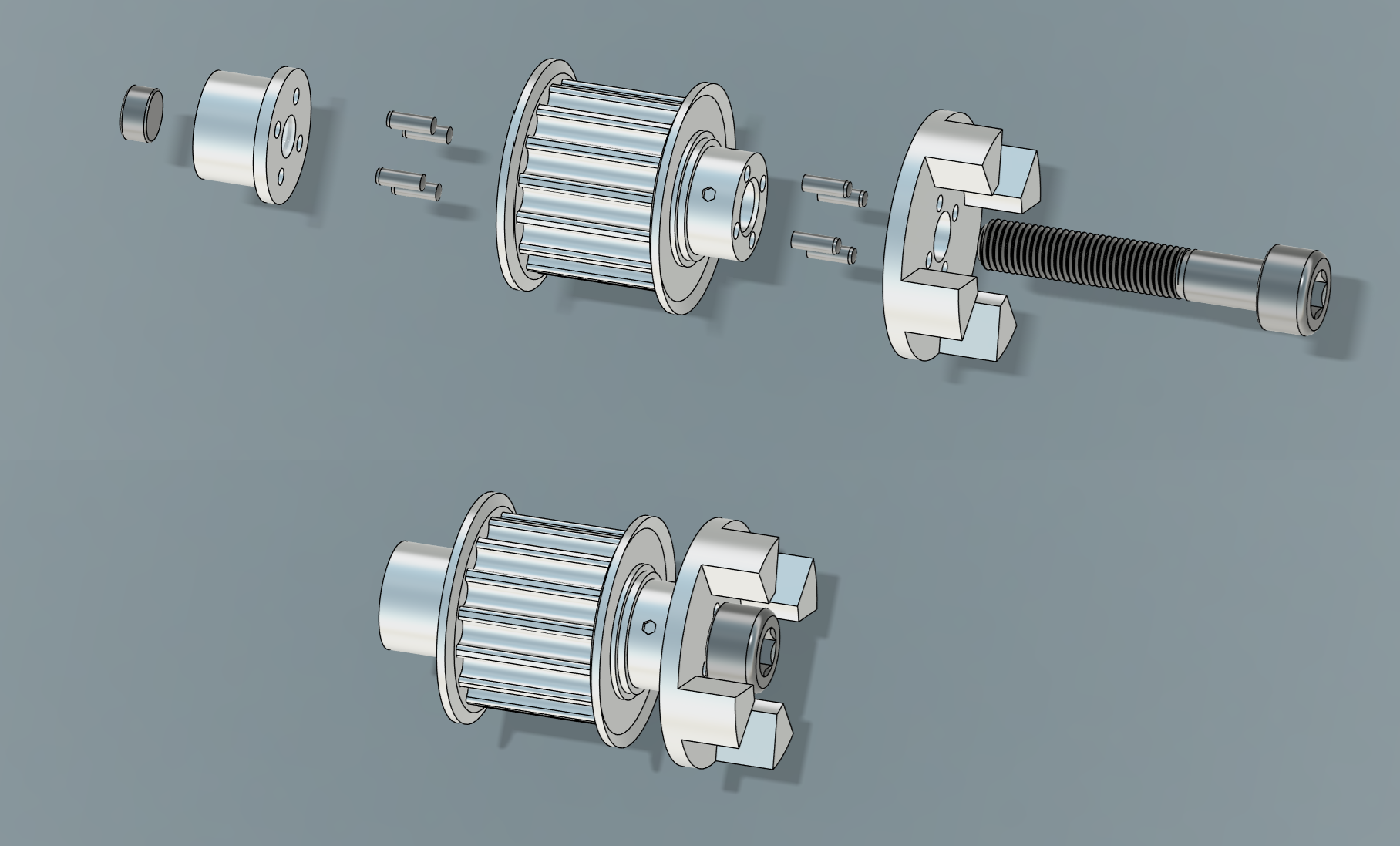
This is part of a long tradition of unholy drive shaft couplings going all the way back to Cap Kart for which I couldn't really tell you what material path is actually transmitting the torque. Is it the friction from the 6mm bolt clamping three pieces together? Or is it the shear pins? Or do the pins just keep the 6mm bolt from unthreading? Is some of the torque going through the bolt itself?? I could probably dig through an old textbook or simulate it to figure it out, but I like the mystery. Most importantly, it allows for an additional R8 bearing to fit between the pulley and the coupler, just barely, without shifting the motor mounting plane or the belt position:
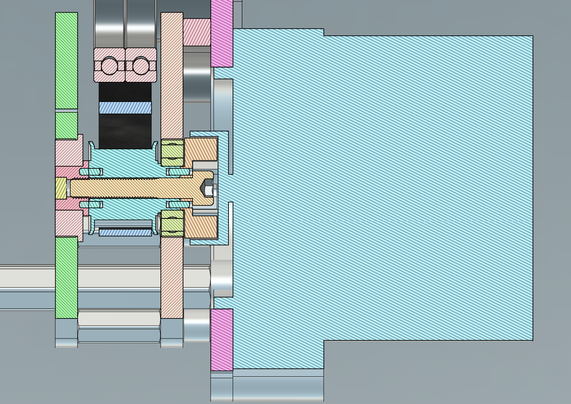
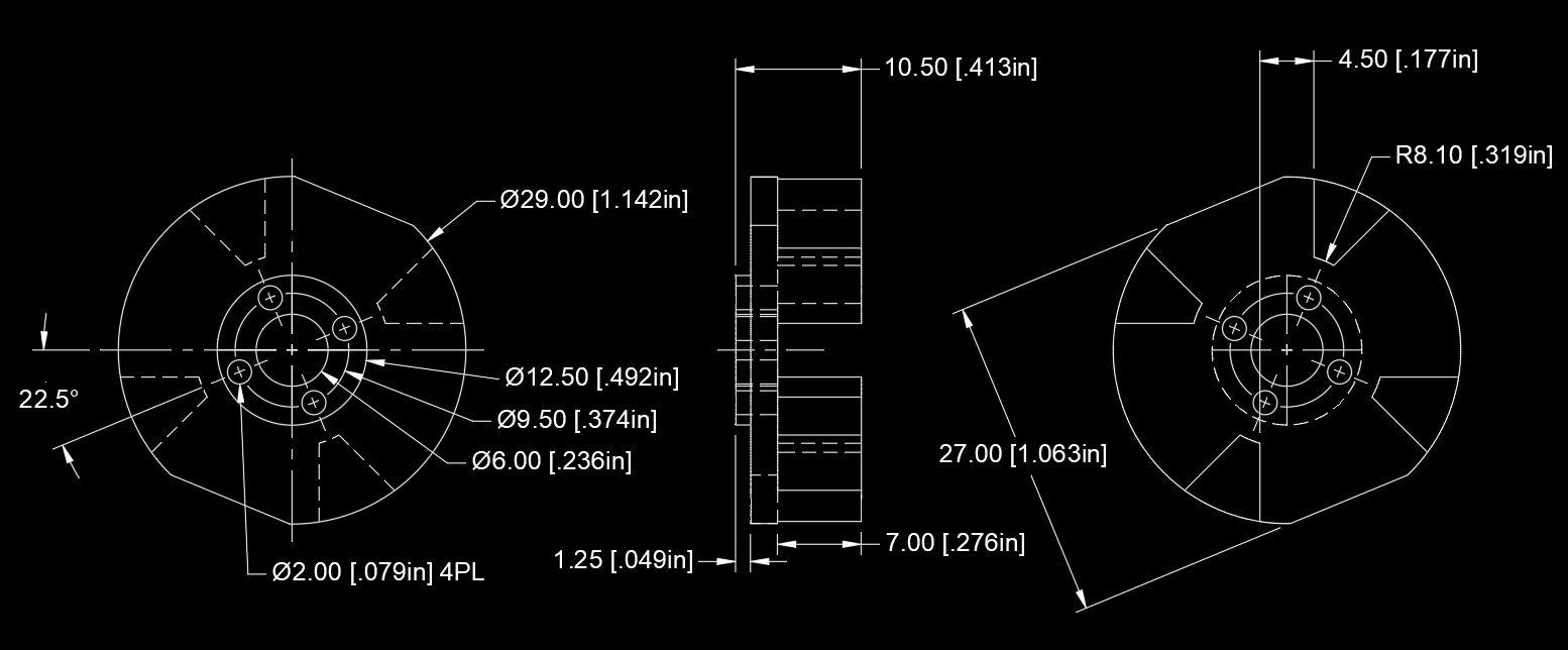
There is 1mm of clearance between the pulley flange and the new bearing, and 0.33mm of clearance between the bearing and the coupler. It's an absurd packaging and I love it. It's also reasonably easy to machine. The coupler looks like it has some complex angles, but it's really just 4.5mm-width straight cuts along 45º radials:
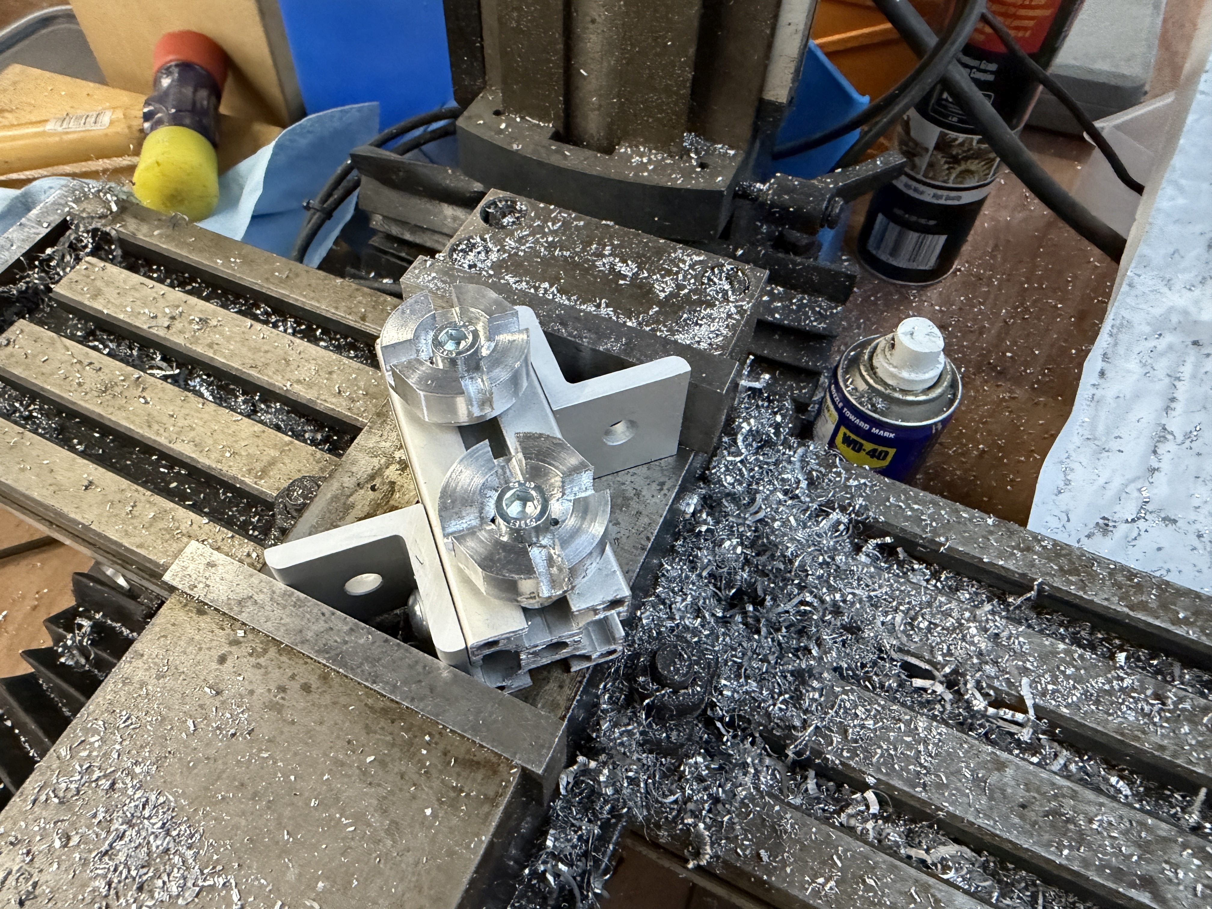
That makes it possible to do on a manual mill, at least with some amount of janky 45º fixturing:
And with that, the normal rubber couplings fit right in:
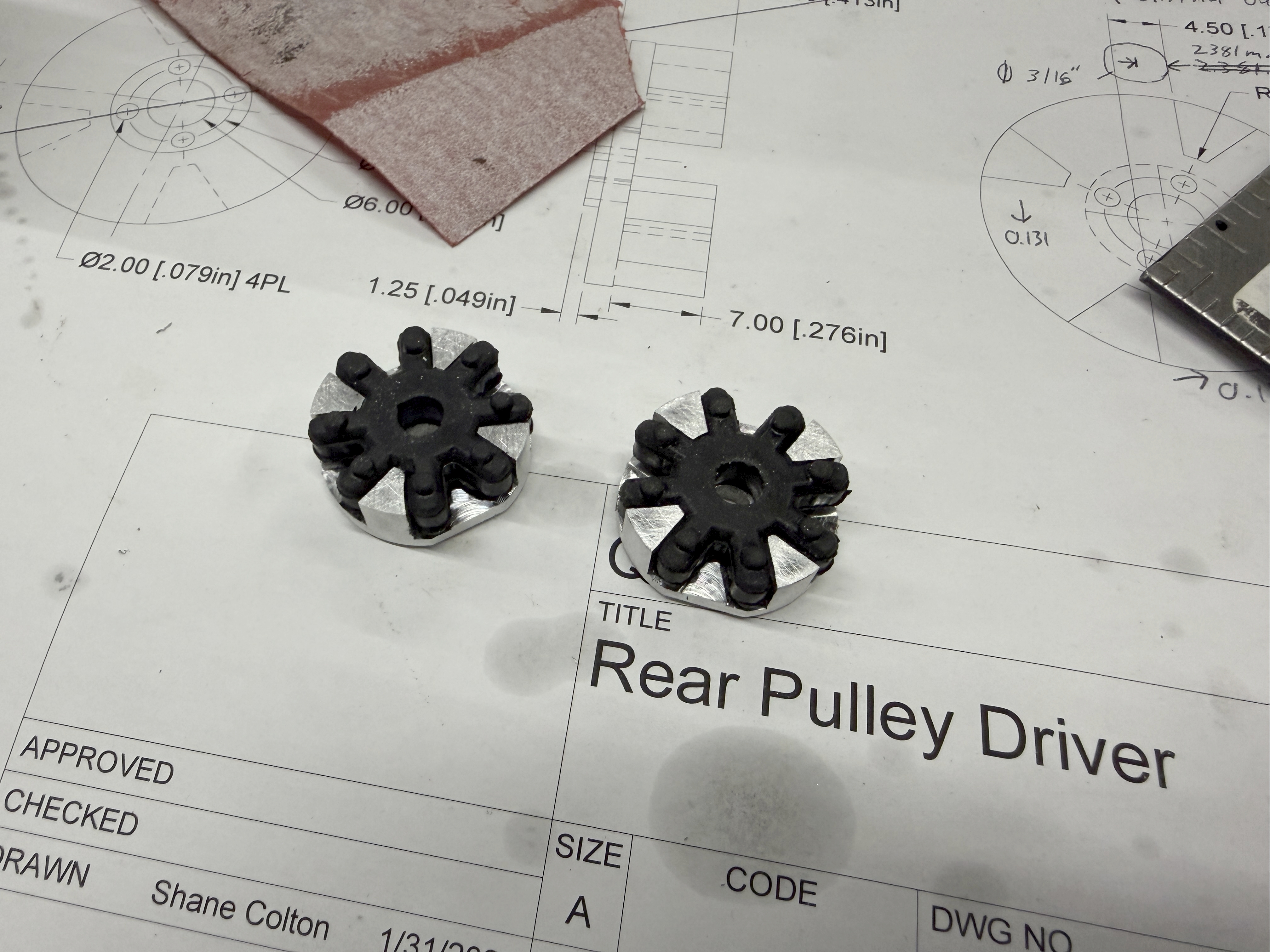
I did have to drill them out to clear the head of the 6mm bolt, but since the torque is transmitted between the teeth (this much I know, at least!), that's no problem. Everything fit together as expected, which is to say with almost no clearance, to make a nice adapter module that occupies in the same space as the old drive shaft support:
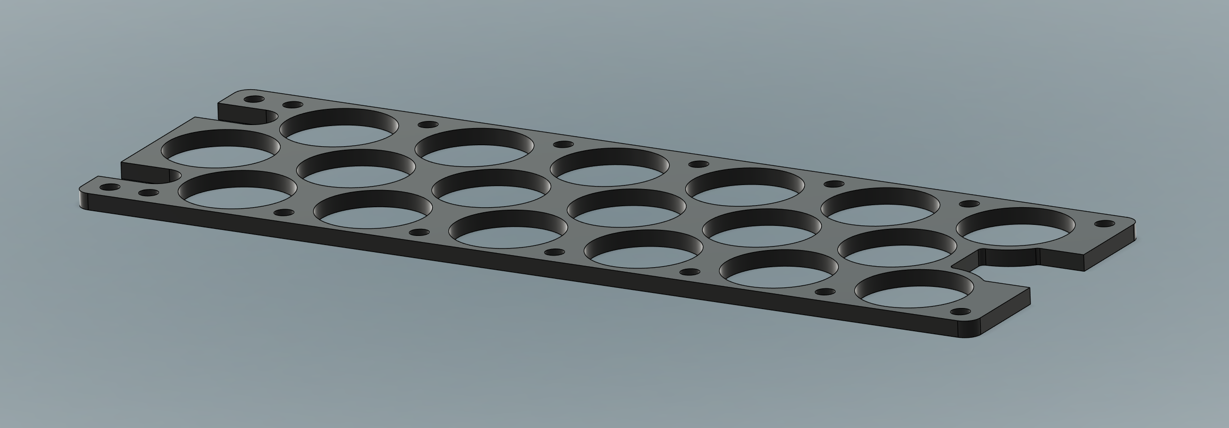
That still leaves the motor mounting, though, and there was no way to easily adapt the existing plate to fit the new motor. It had to be re-cut entirely:
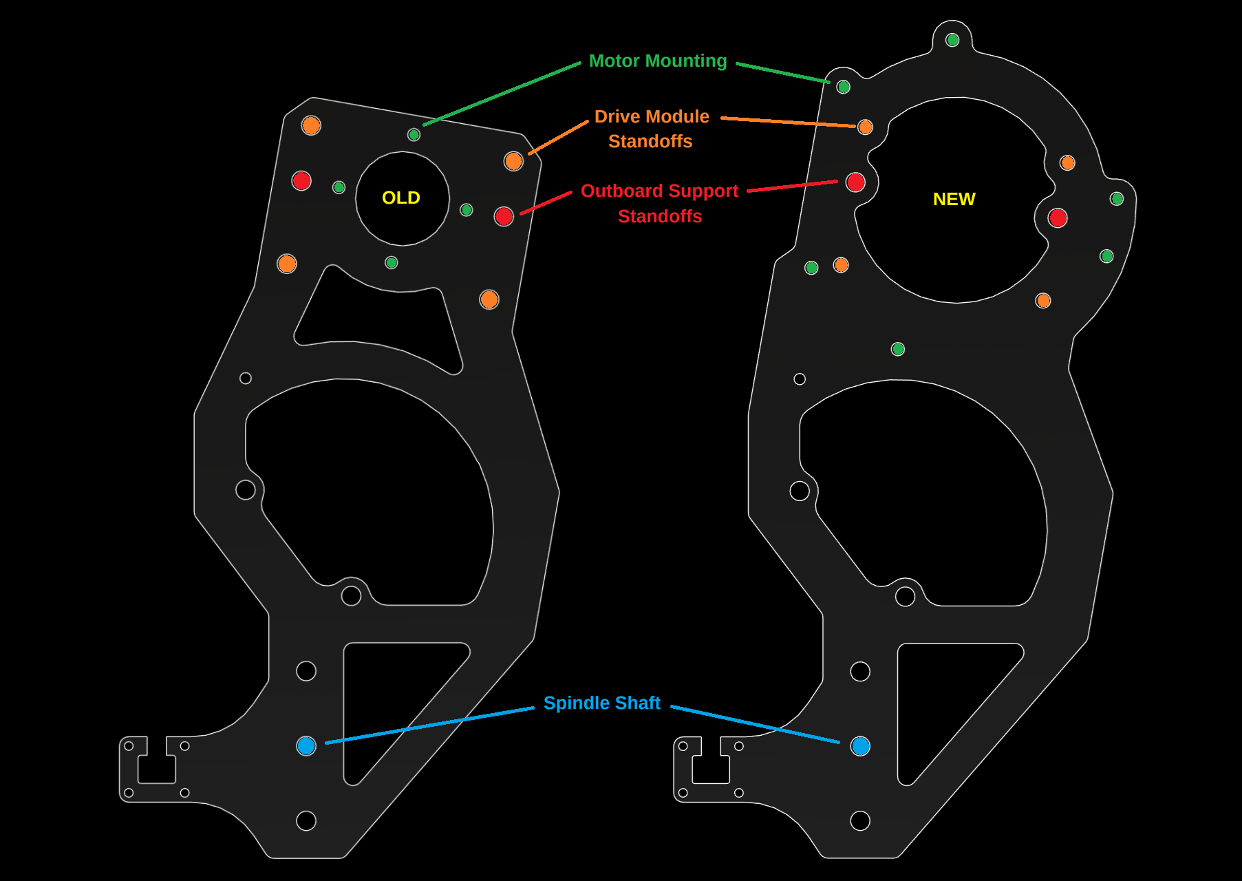
Some of the existing standoff holes also encroach on the motor's inner flange circle, so unfortunately this adaptation doesn't work with the bone-stock Hyundai EPS motor. I had to mill down the flange where it would interfere. Think of it as weight reduction. Speaking of which, the automotive wire harness can also go away:
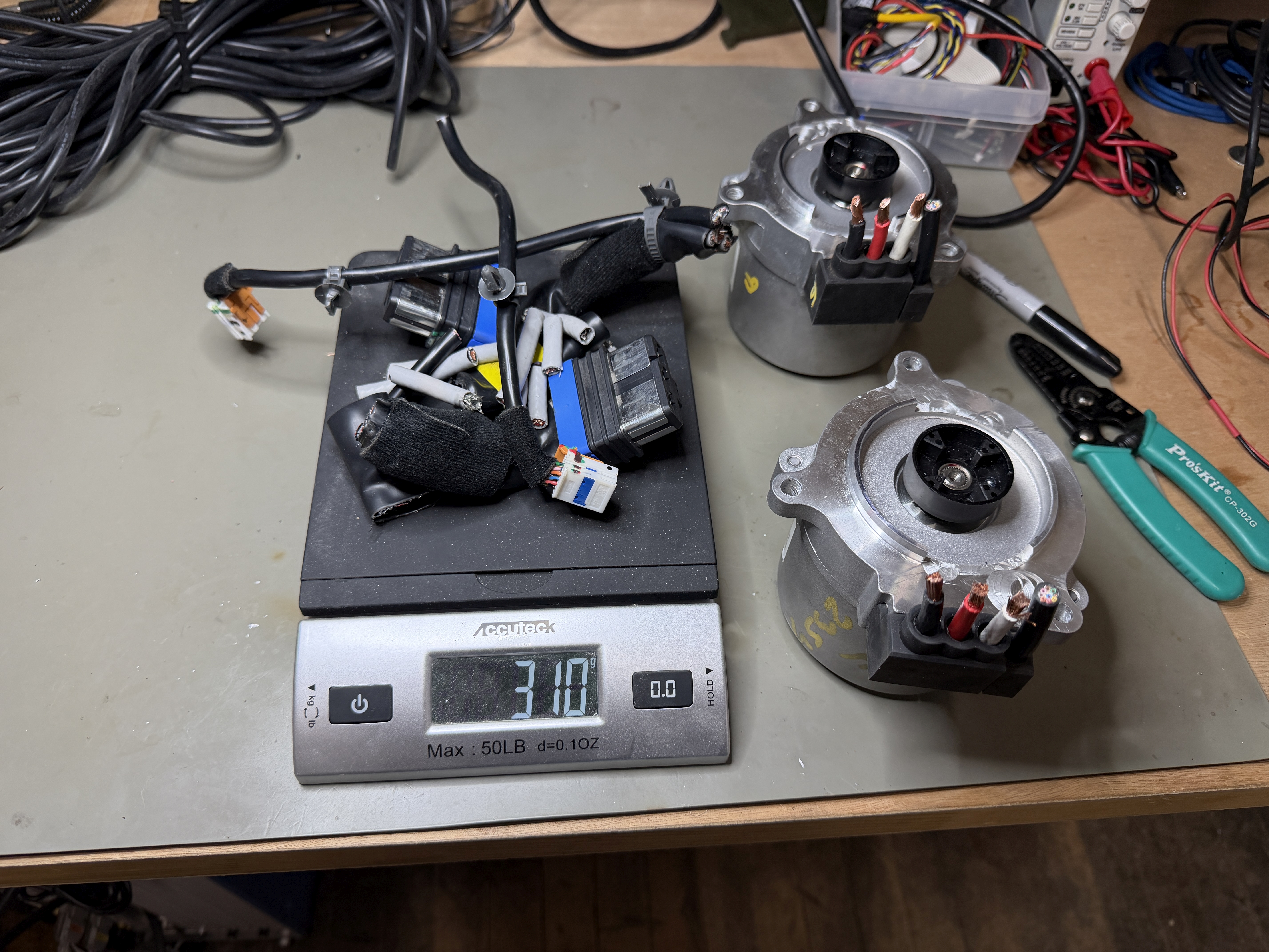 |
| Don't need any of that... |
And after a changing a few tight-fit clearance holes to loose-fit to soak up some measurement errors on the motor's mounting pattern, everything fits together well enough:
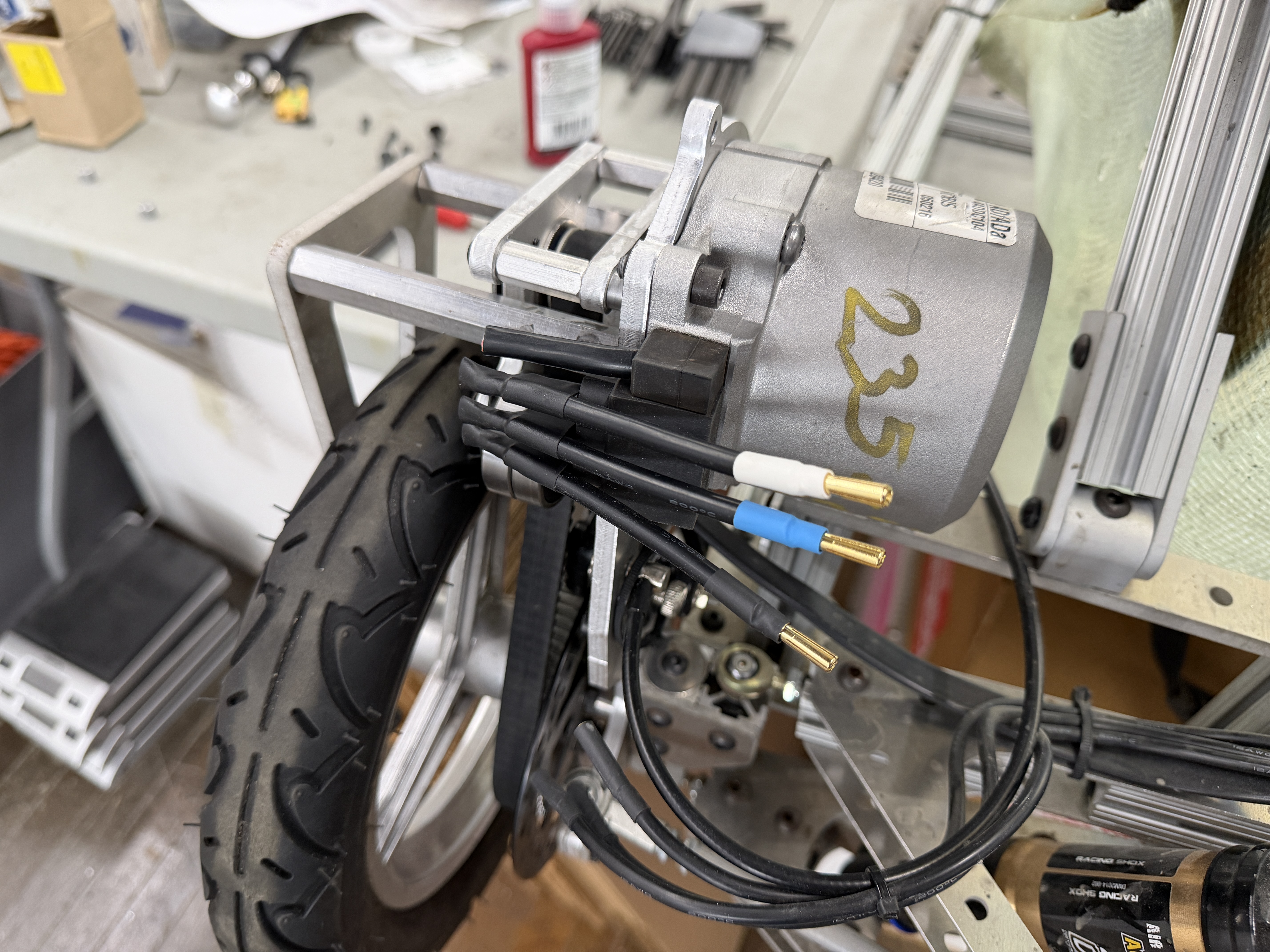
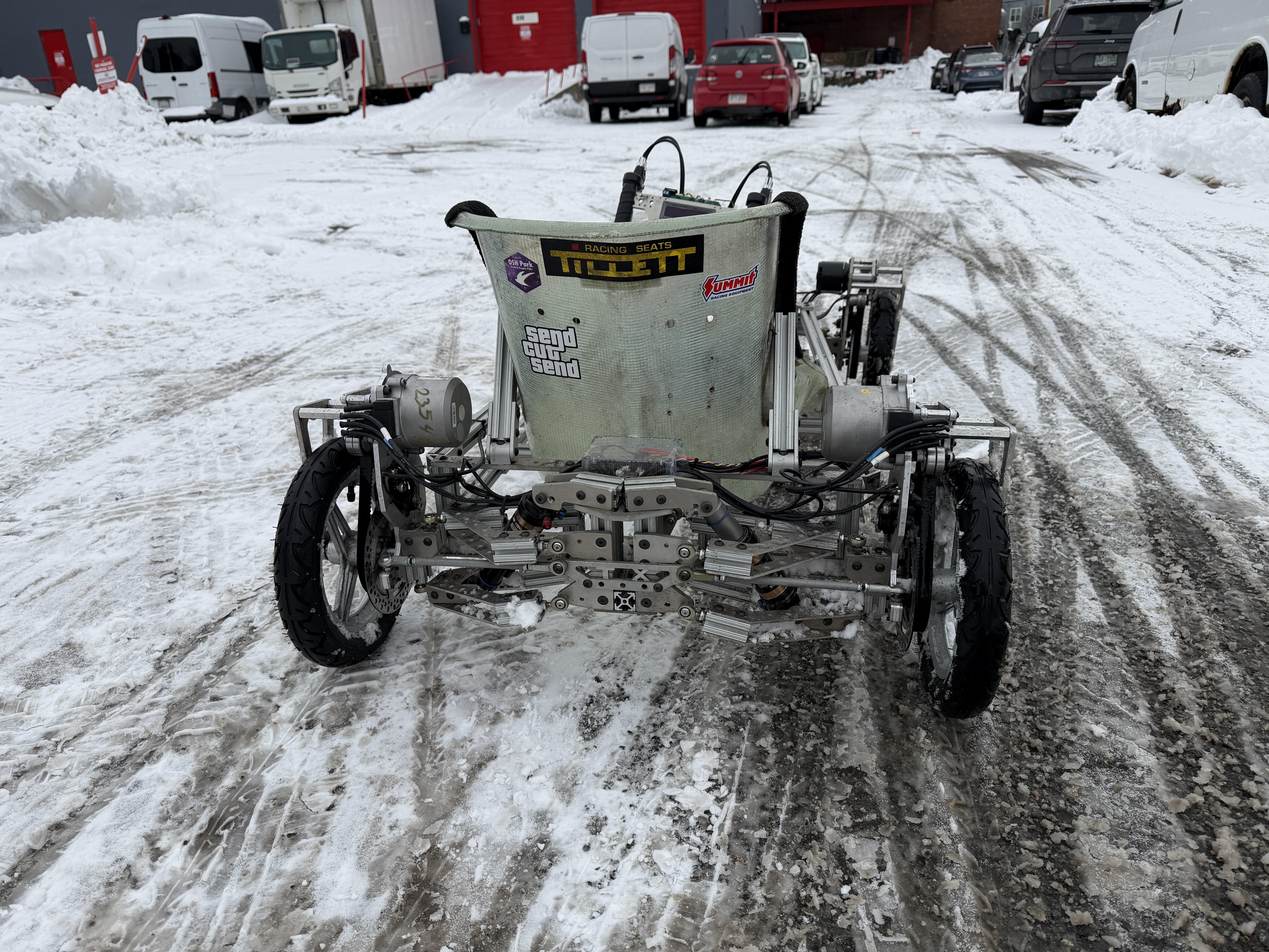
Even though it's substantially larger than the APS 6374, it doesn't look overly bulky or out-of-place in the design. I actually really like the look of the motor's cast aluminum housing to go with the rest of the aluminum chassis. The total weight for the kart without batteries is just a bit over 40kg now. I don't think I can offset the extra weight of these motor completely, but I may at least try to get it back under 40kg at some point.
The Hyundai EPS motors do include some kind of position encoder, maybe a resolver? But I decided to just use the existing outboard sense magnet and rotary angle sensor. Despite the rubber coupling, I think that will be sufficiently accurate with only three pole pairs. (The electrical angle error is only 3x the mechanical angle error instead of 7x.) So I reprogrammed those sensors for six poles and...oh, that's right, one of the rear quadrants suffered a bit of a meltdown last year:
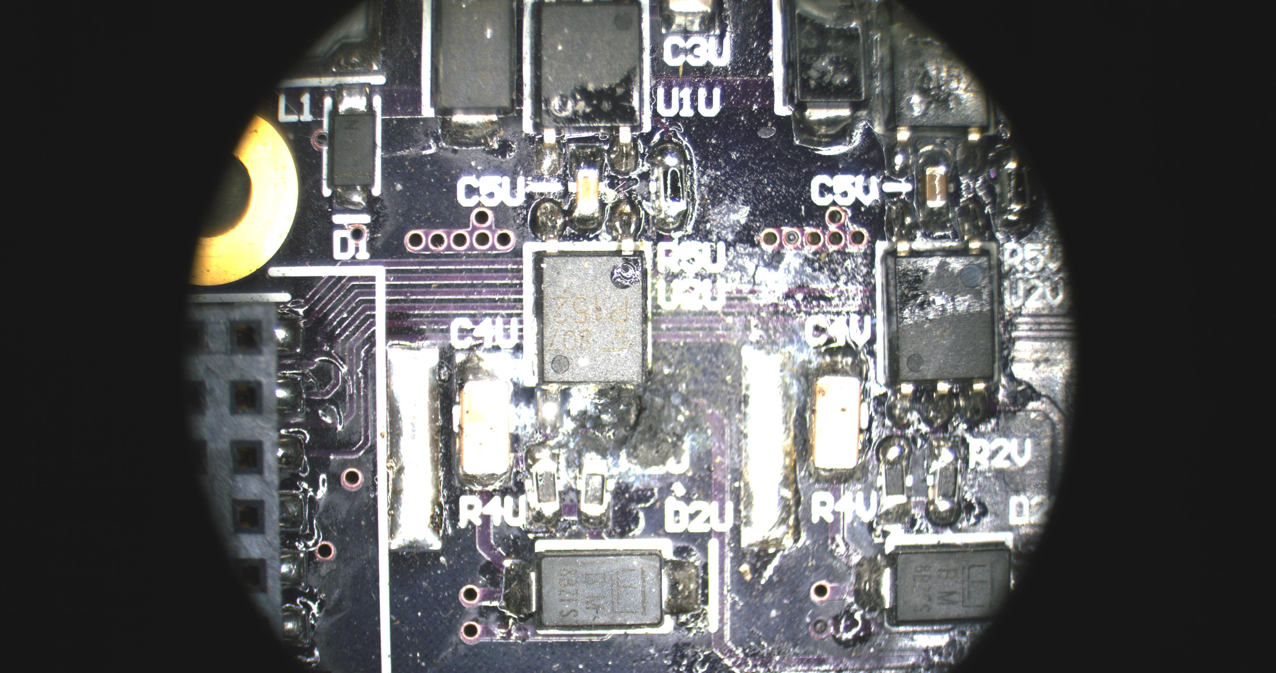
I'm not sure the exact sequence of events, but I think the sensor board got wet and stopped working, then the desynchronized motor windings got too hot and failed short, then one of the low-side FETs died, taking out its gate driver with it. Meanwhile, the other three motors were pulling me along well enough that I didn't notice the problem until it became an odor. Interestingly, it seems to be the FET gate that died; the D-S path was not shorted. I'm not going to think about it too hard right now. I just replaced the FET and gate driver and everything was happy again.
We've had some massive snowstorms this year that cumulatively add up to more than the height of the kart, but the latest one came with a bonus round of an extra inch after the plows had already done the parking lots. This is the perfect amount for some quick snow karting (another tradition):
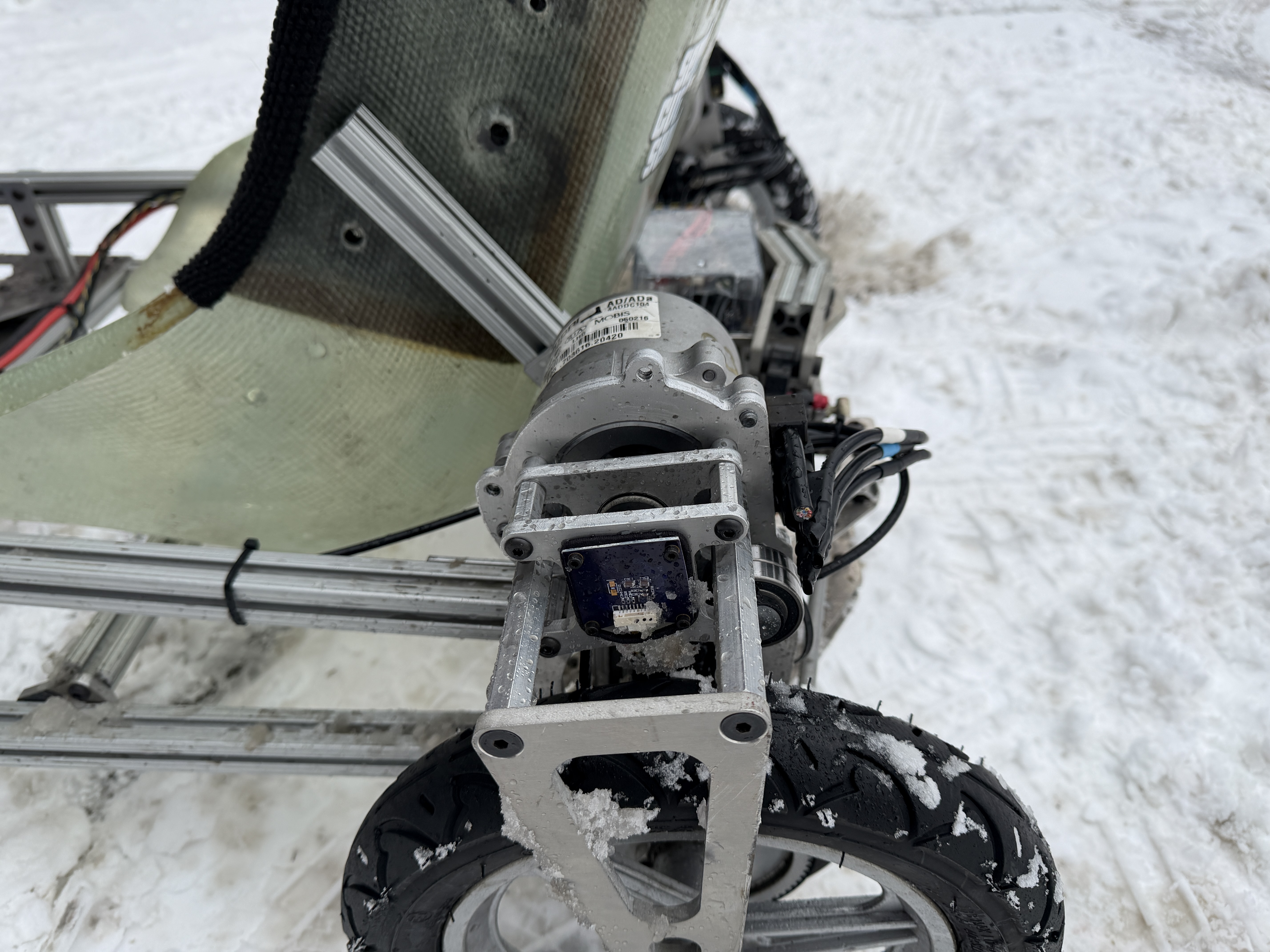 |
| The sensor board conformal coating is holding up, somehow. |
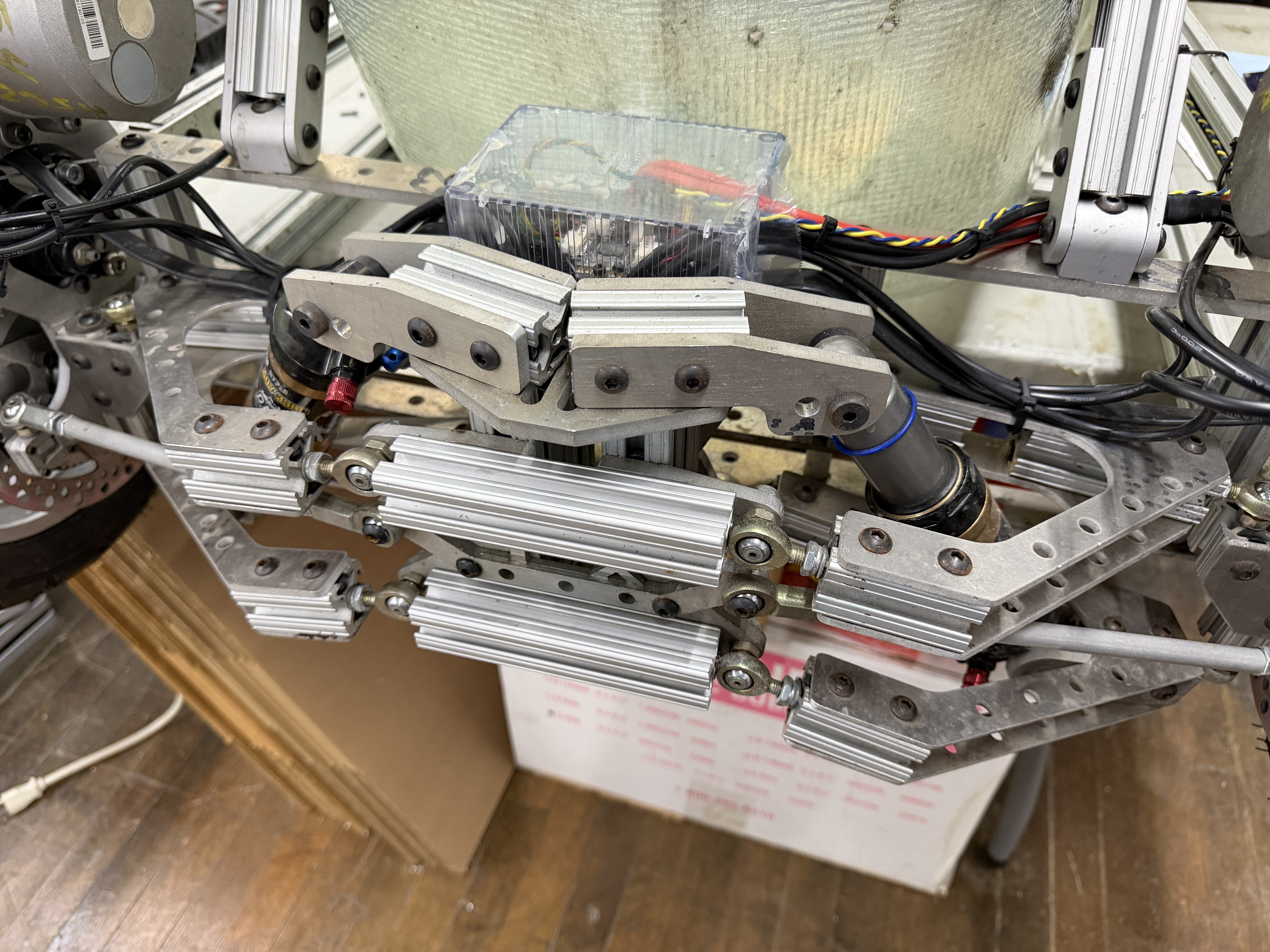
At 80-100A, the Hyundai EPS motors feel pretty much identical to the APS 6374 170KV. They can easily generate and control oversteer on the snow. And after half a battery pack of messing around, they were staying nice and cool. So I think they do have some overhead now, if I want to push even more current in dry conditions. The main problem will be the suspension:
The A-arm flex is not good, even at 100A. At first glance, it seems like most of the displacement is originating from the two quarter-inch aluminum plates that hold the rear ball joints. They're only flexing a little, but that angular offset creates a lot of displacement at the plane of the wheel. Luckily, it's easy to reinforce these - just add even more 80/20:
I'm sure there's an even lighter way to do this, but it actually looks like it belongs. It also gives some new mounting points for accessories, cameras, etc. I will add one to the front as well. Only the top is needed there; the steering linkage bearing plate handles the bottom. Of course, these are even more weight that I now need to offset to get it back under 40kg.
But for now, I think this upgrade is complete. I still need to test the motors at speed when (if) the snow ever melts. They do have higher inductance than the APS 6374 170KV, which might limit their maximum power. They're also designed for 12V, not 48V, so they might lose efficiency at higher speeds due to speed-squared losses. I'll have to do some data logging to find out.
The next upgrade is also in the works...here's a teaser: