Showing posts with label TinyCross. Show all posts

Friday, February 27, 2026

TinyCross: Rear Motor Update

In its original design, TinyCross used four identical Alien Power System 6374 170rpm/V brushless motors. But with the weight distribution being heavily biased to the rear, it really makes more sense to use larger motors there. I had seen some examples of electric power steering motors that might be suitable, so I did some eBay exploration to see what was available. I settled on a Hyundai part (56300F2200) that looked common enough that I could always find spares:
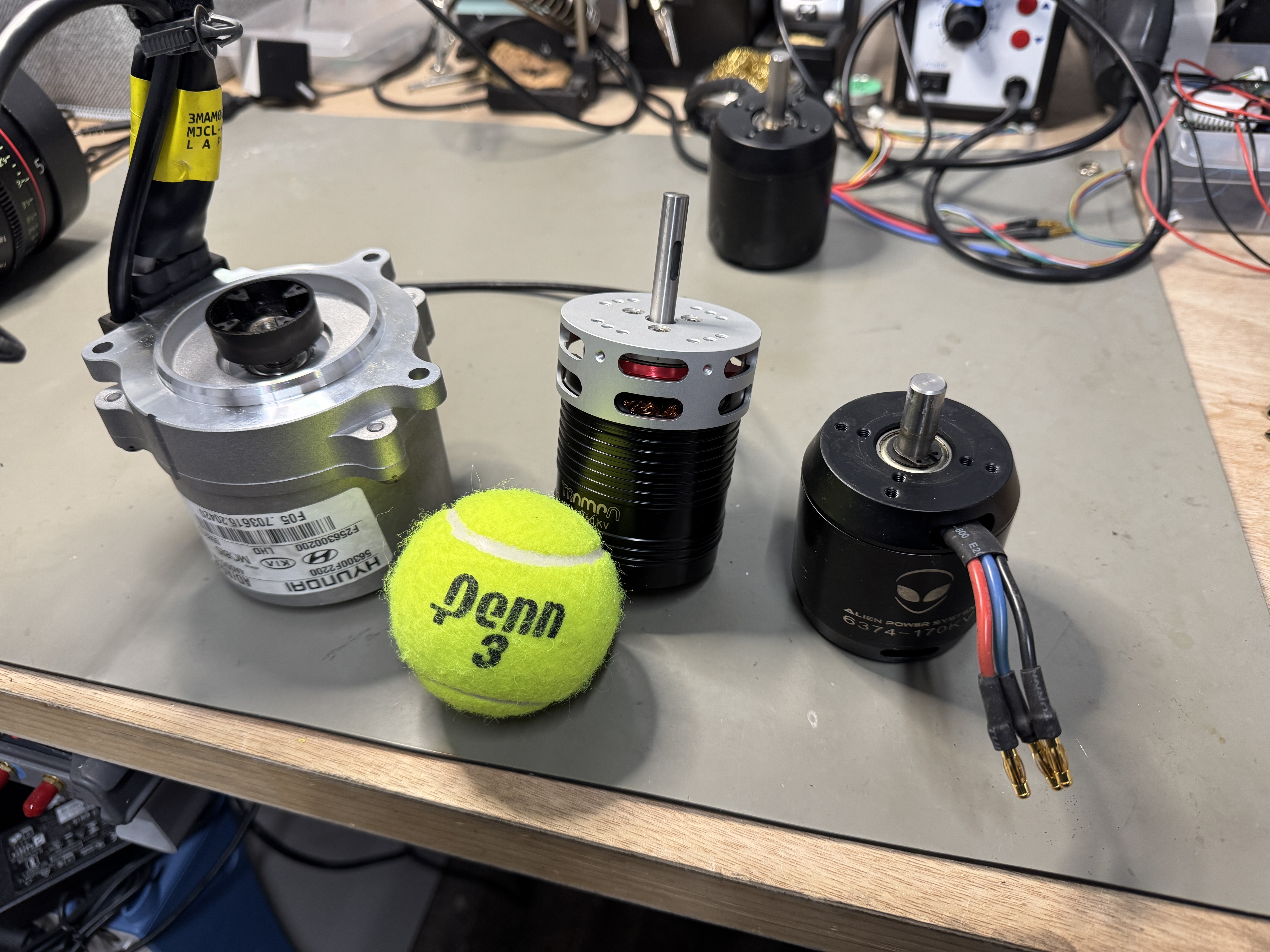
Hyundai EPS Motor (left), Trampa 6376 (middle), APS 6374 (right)

I was surprised to find that the torque constant (and thus rpm/V) of the Hyundai EPS motor was actually very similar to the APS 6374 170KV, meaning it could just drop into the design with the same gear ratio. The main difference is that the EPS motor is a 6-pole inrunner instead of a 14-pole outrunner. This makes it easier to get heat off of the stator winding. The resistance is also much lower, and the wire gauge going in suggests it can probably handle even more than the 100A peak I've been running in the rear. But the extra performance overhead comes at a price...it's big!

Although this motor is relatively small in the context of automotive electric power steering, it's still a lot larger than the APS 6374. It weighs almost 2kg with the wire harness still attached, compared to 0.68kg for the APS. It also has a diameter of 88mm and a bolt circle of 109mm, so it would be a tight fit into a drive quadrant designed for a 63mm outrunner with a face mount. The hardest part, though, would be adapting the coupler to TinyCross's drive pulley without increasing the width of the existing design. The original shaft adapter for the APS 6374 used a clamp and key to secure the drive pulley to the 10mm motor shaft:
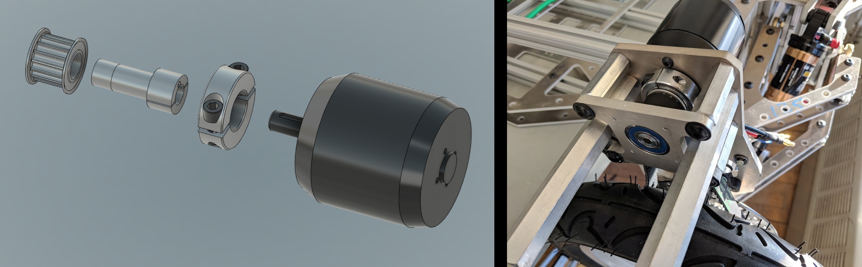
But the Hyundai EPS motor has a large plastic coupling-half pressed onto a short spline shaft, intended to interface to a mating part with a flexible rubber coupler. So, unlike the old design, the drive shaft can't use the motor's bearing as one of its supports. I would need to add both another bearing and the mating coupling-half to the pulley shaft, without changing the belt location. 

I played with this in CAD for a while and determined that it would probably require moving the motor mounting plane inboard to make more room for the new drive shaft. That was more work than I wanted to do at the time, so I put the project aside for a few months. But luckily when I came back to it, I drew up this evil thing instead:
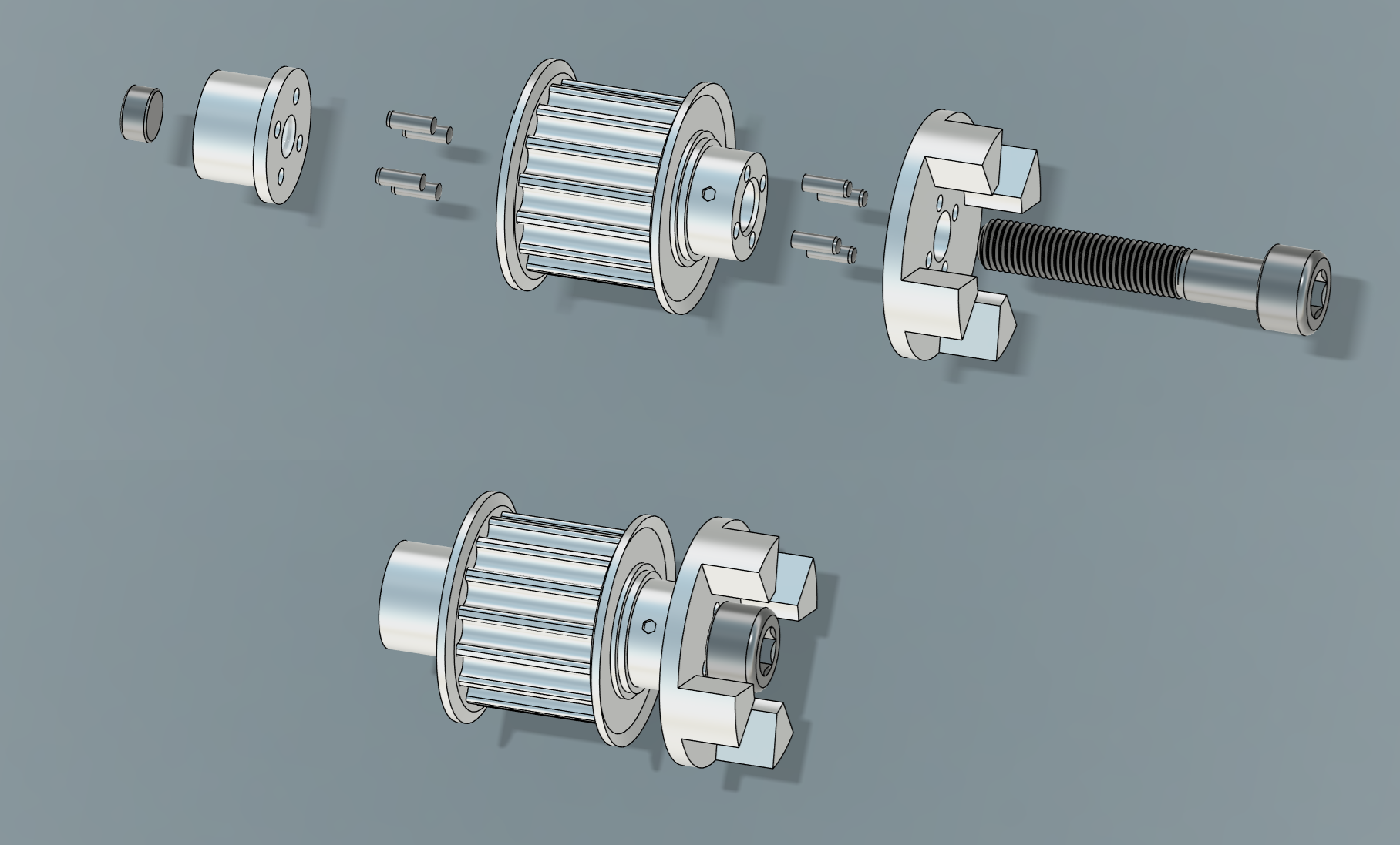
This is part of a long tradition of unholy drive shaft couplings going all the way back to Cap Kart for which I couldn't really tell you what material path is actually transmitting the torque. Is it the friction from the 6mm bolt clamping three pieces together? Or is it the shear pins? Or do the pins just keep the 6mm bolt from unthreading? Is some of the torque going through the bolt itself?? I could probably dig through an old textbook or simulate it to figure it out, but I like the mystery. Most importantly, it allows for an additional R8 bearing to fit between the pulley and the coupler, just barely, without shifting the motor mounting plane or the belt position:
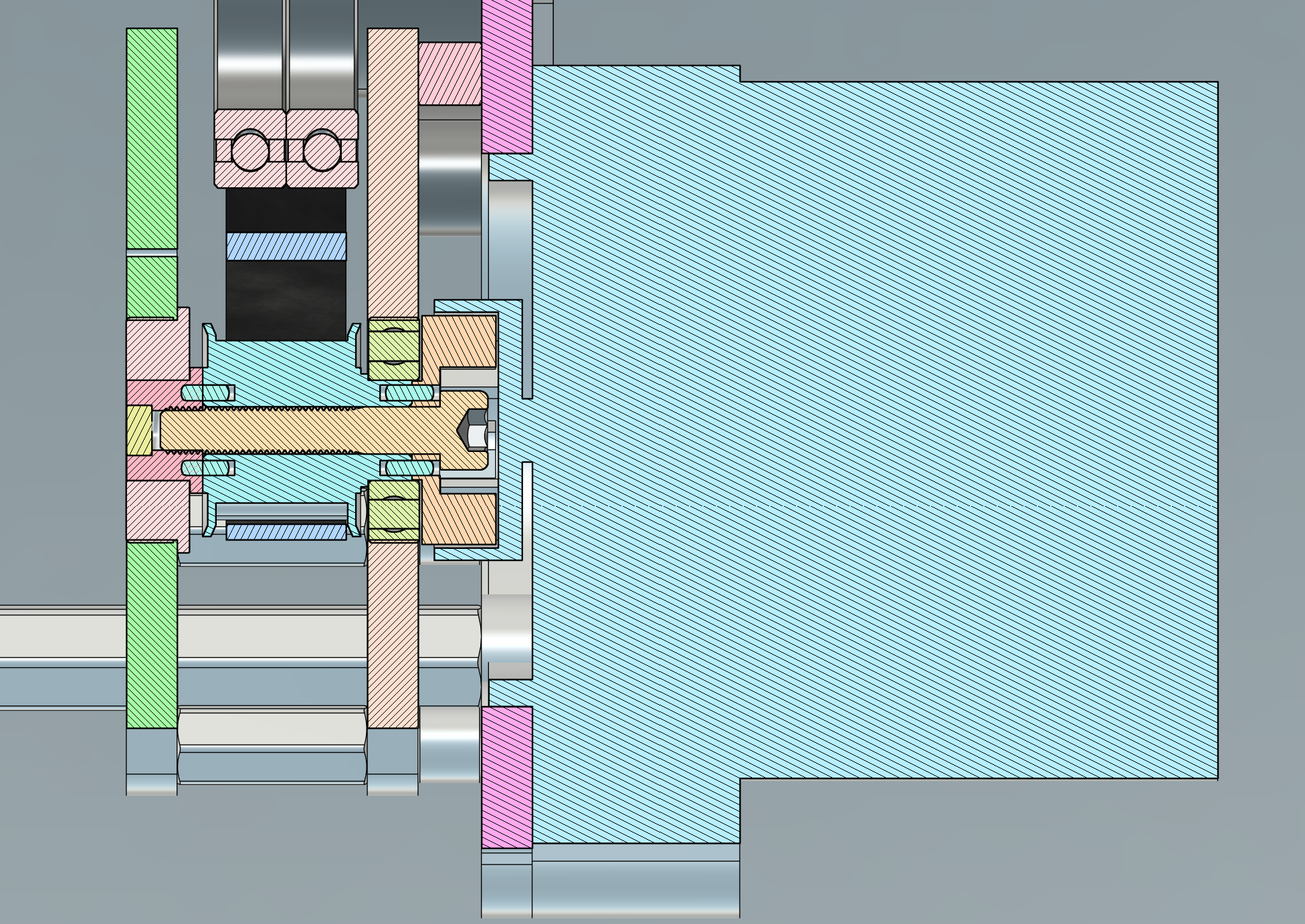
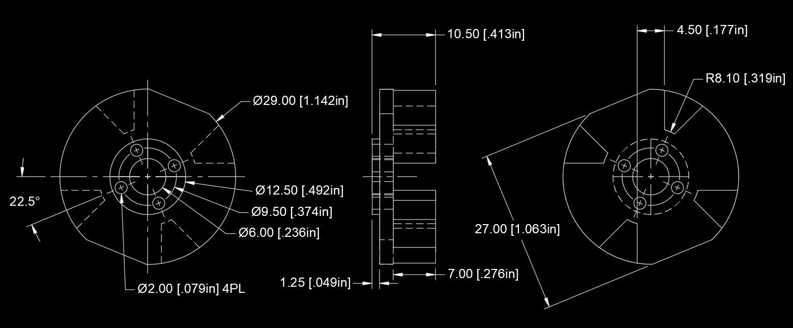
There is 1mm of clearance between the pulley flange and the new bearing, and 0.33mm of clearance between the bearing and the coupler. It's an absurd packaging and I love it. It's also reasonably easy to machine. The coupler looks like it has some complex angles, but it's really just 4.5mm-width straight cuts along 45º radials:
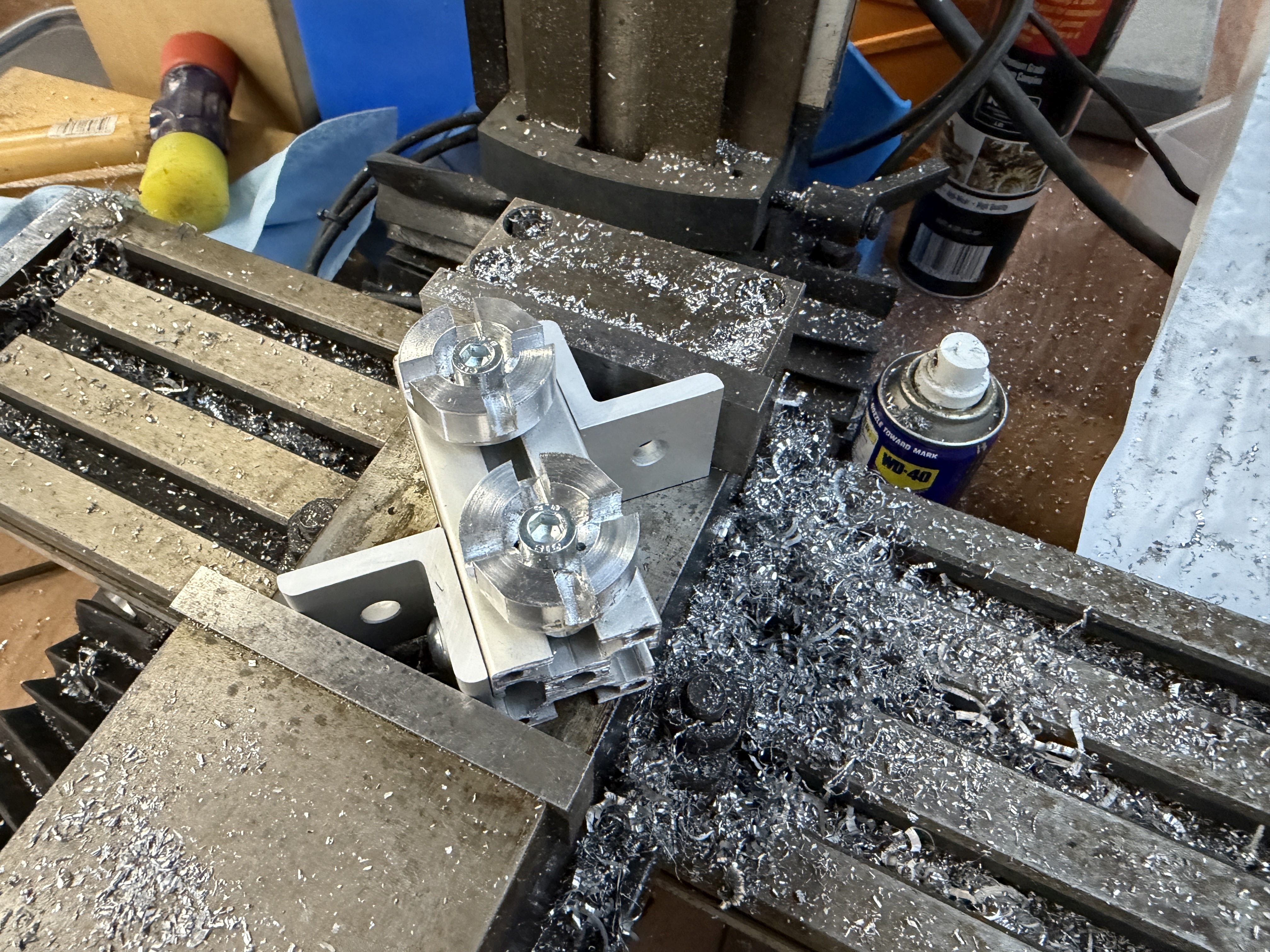
That makes it possible to do on a manual mill, at least with some amount of janky 45º fixturing:
And with that, the normal rubber couplings fit right in:
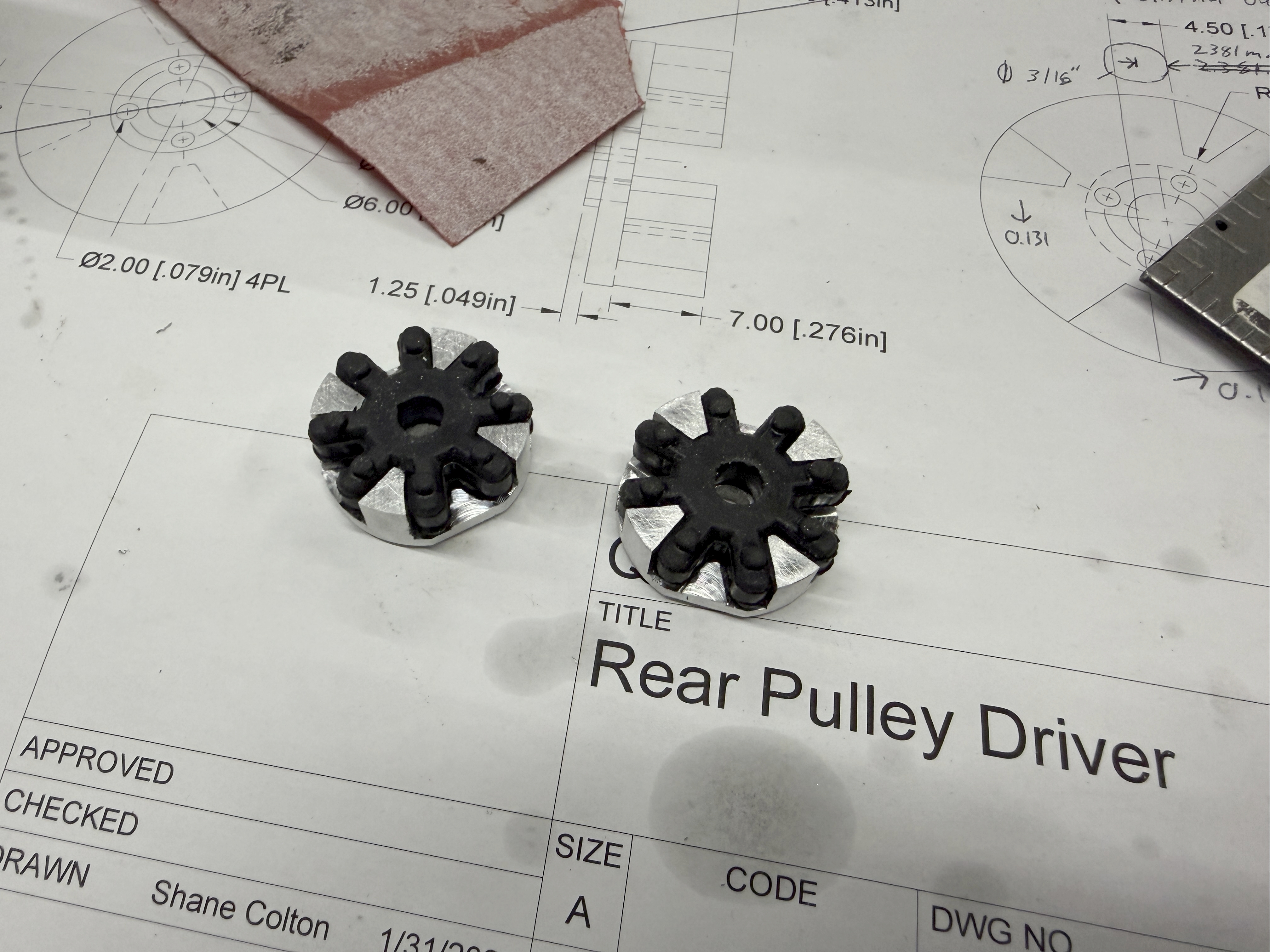
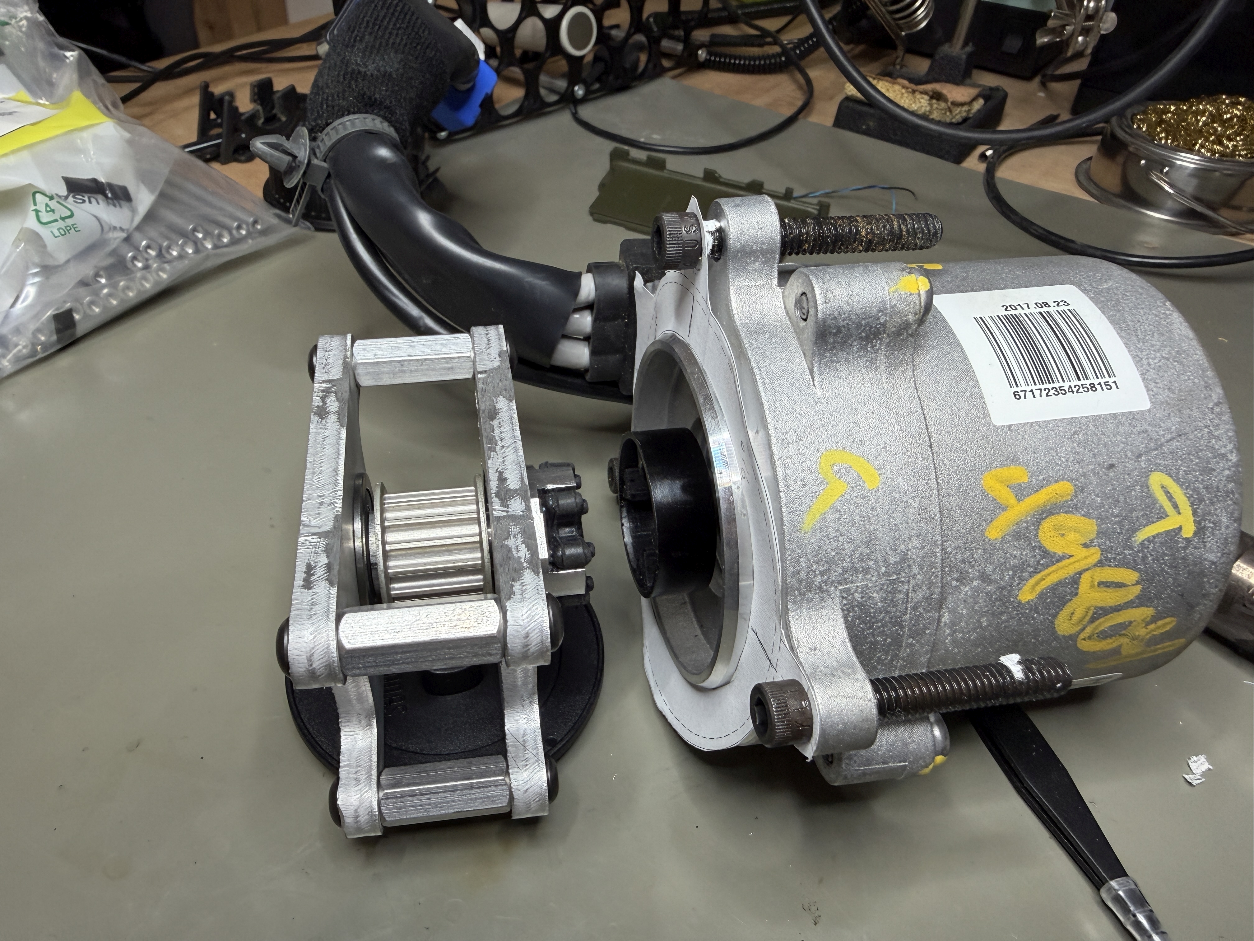
I did have to drill them out to clear the head of the 6mm bolt, but since the torque is transmitted between the teeth (this much I know, at least!), that's no problem. Everything fit together as expected, which is to say with almost no clearance, to make a nice adapter module that occupies in the same space as the old drive shaft support:
That still leaves the motor mounting, though, and there was no way to easily adapt the existing plate to fit the new motor. It had to be re-cut entirely:
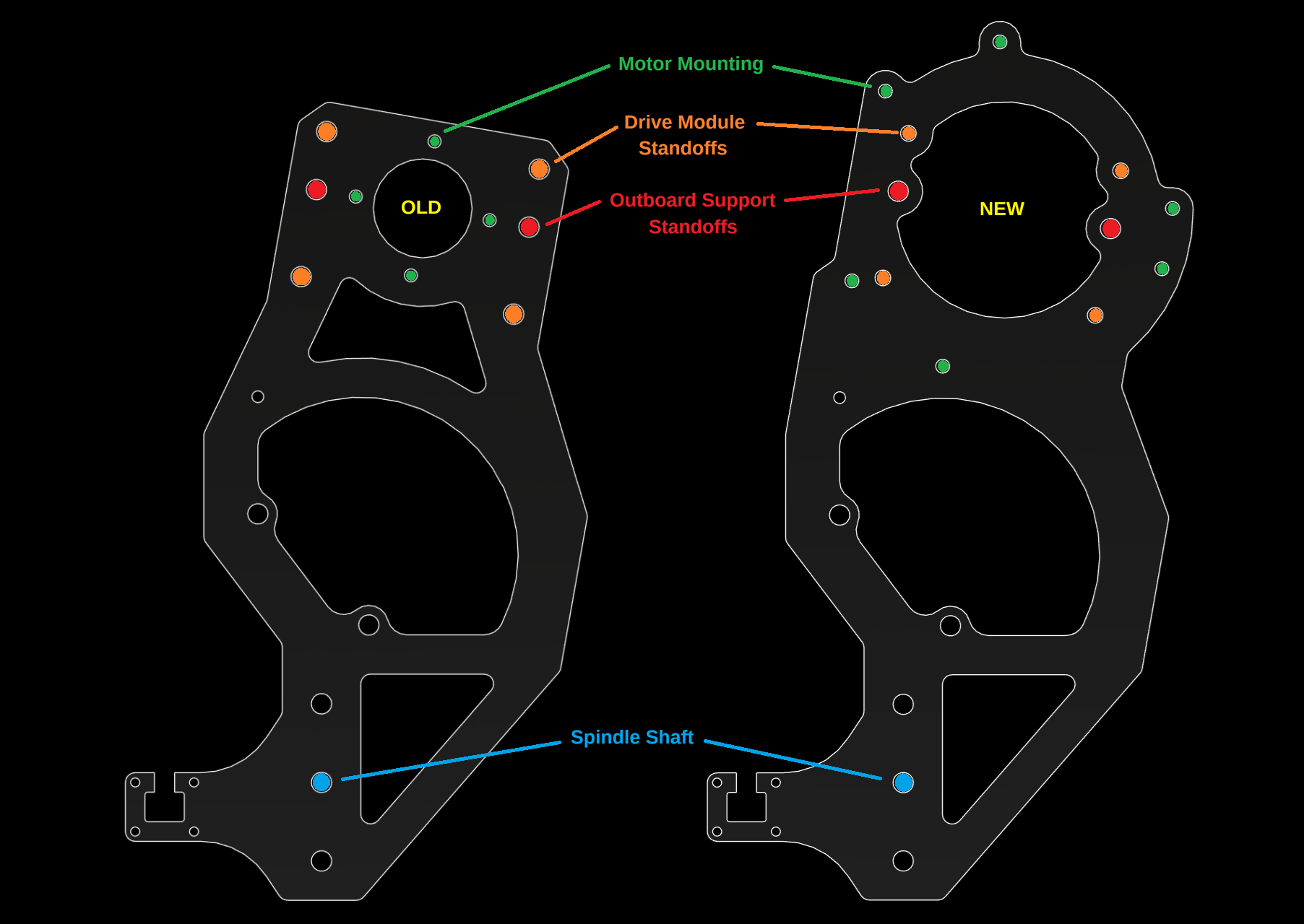
Some of the existing standoff holes also encroach on the motor's inner flange circle, so unfortunately this adaptation doesn't work with the bone-stock Hyundai EPS motor. I had to mill down the flange where it would interfere. Think of it as weight reduction. Speaking of which, the automotive wire harness can also go away:
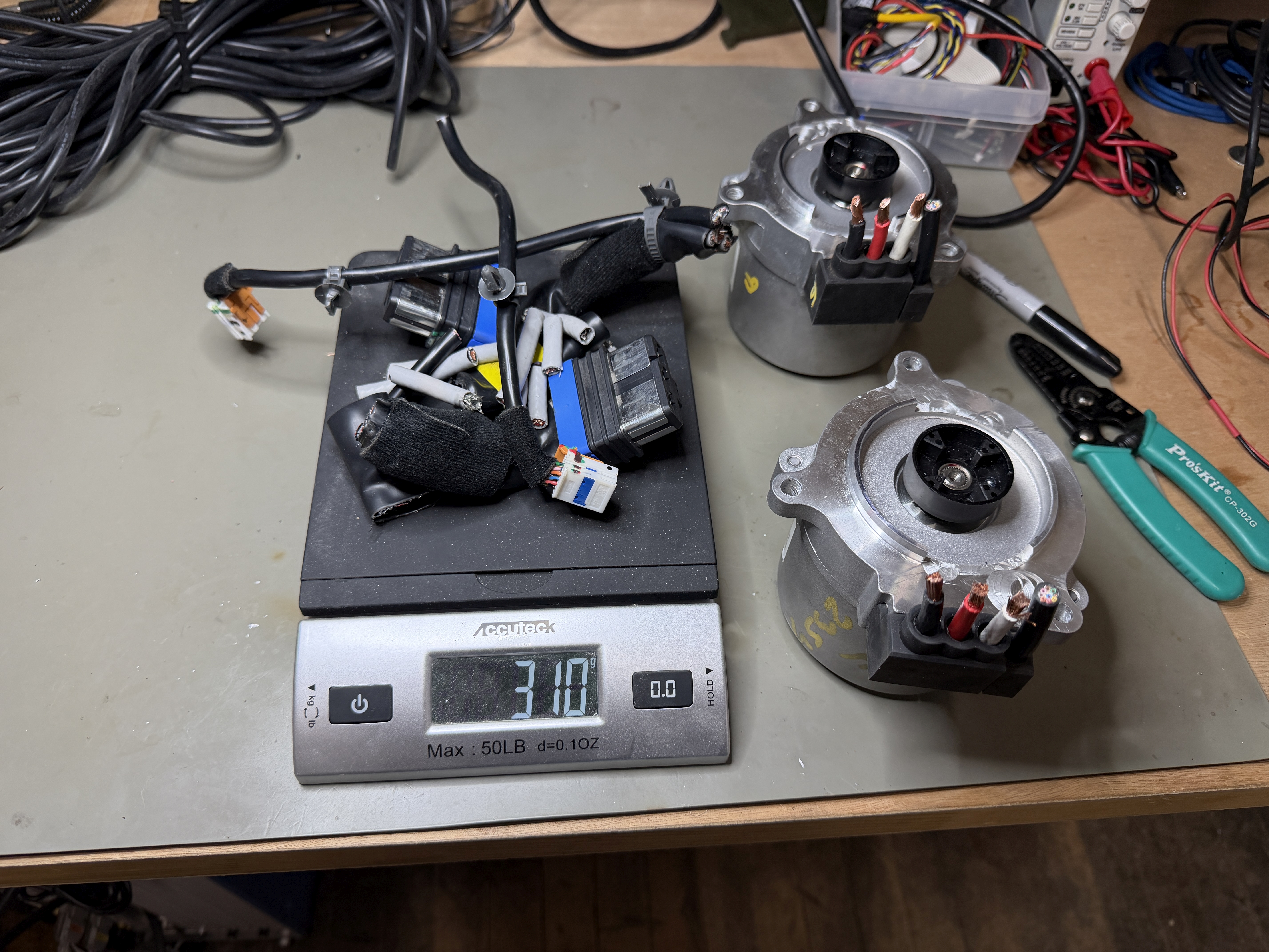
Don't need any of that...

And after a changing a few tight-fit clearance holes to loose-fit to soak up some measurement errors on the motor's mounting pattern, everything fits together well enough:
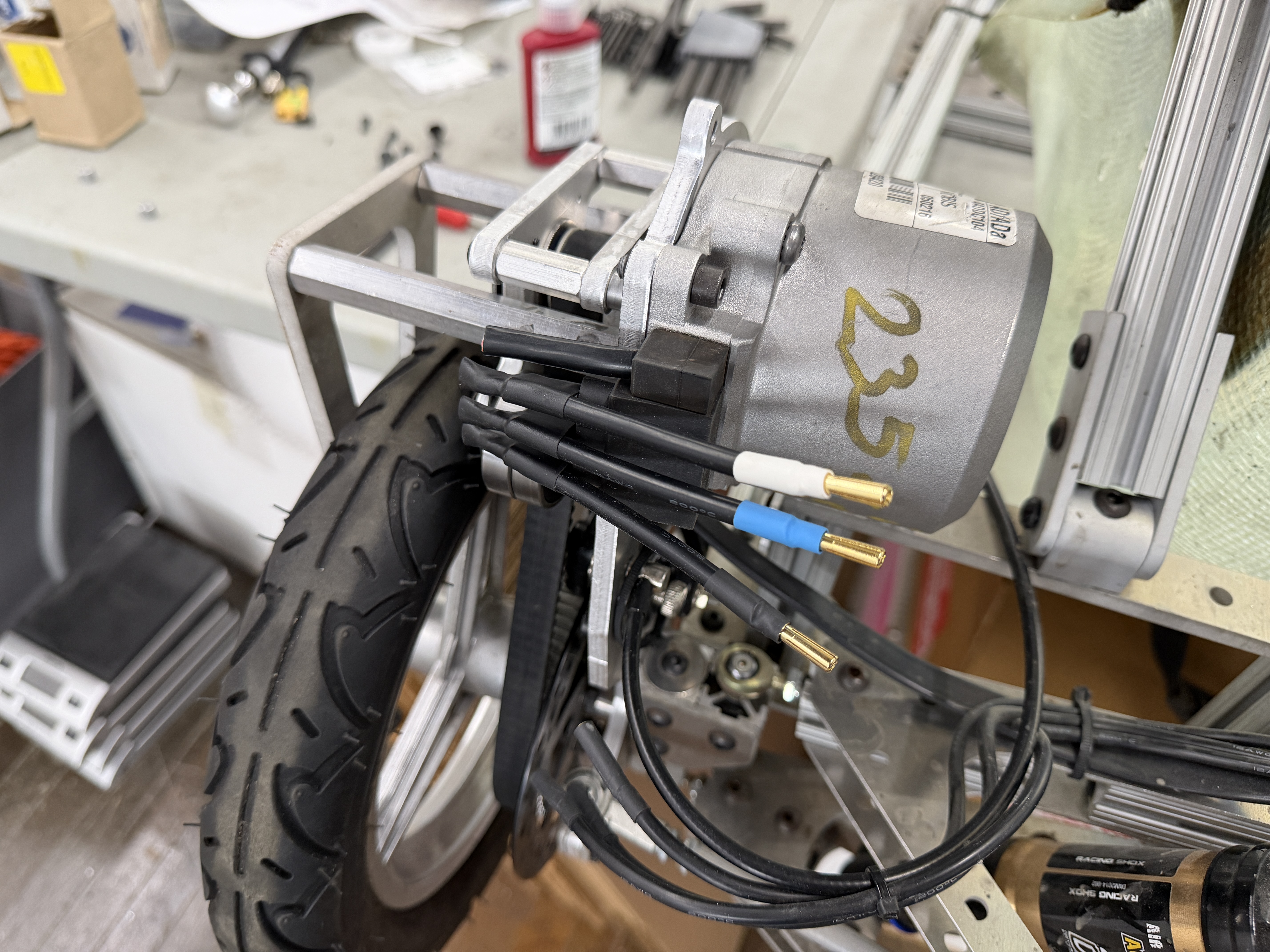
Even though it's substantially larger than the APS 6374, it doesn't look overly bulky or out-of-place in the design. I actually really like the look of the motor's cast aluminum housing to go with the rest of the aluminum chassis. The total weight for the kart without batteries is just a bit over 40kg now. I don't think I can offset the extra weight of these motor completely, but I may at least try to get it back under 40kg at some point.

The Hyundai EPS motors do include some kind of position encoder, maybe a resolver? But I decided to just use the existing outboard sense magnet and rotary angle sensor. Despite the rubber coupling, I think that will be sufficiently accurate with only three pole pairs. (The electrical angle error is only 3x the mechanical angle error instead of 7x.) So I reprogrammed those sensors for six poles and...oh, that's right, one of the rear quadrants suffered a bit of a meltdown last year:
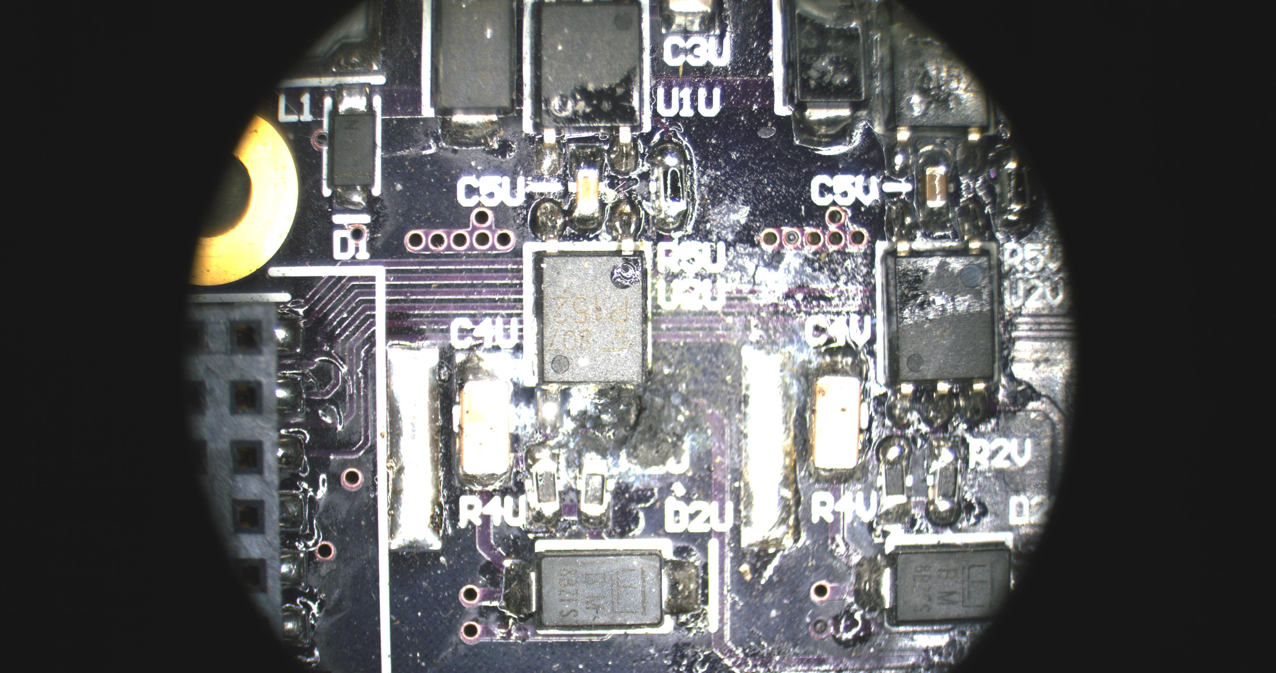
I'm not sure the exact sequence of events, but I think the sensor board got wet and stopped working, then the desynchronized motor windings got too hot and failed short, then one of the low-side FETs died, taking out its gate driver with it. Meanwhile, the other three motors were pulling me along well enough that I didn't notice the problem until it became an odor. Interestingly, it seems to be the FET gate that died; the D-S path was not shorted. I'm not going to think about it too hard right now. I just replaced the FET and gate driver and everything was happy again.

We've had some massive snowstorms this year that cumulatively add up to more than the height of the kart, but the latest one came with a bonus round of an extra inch after the plows had already done the parking lots. This is the perfect amount for some quick snow karting (another tradition):
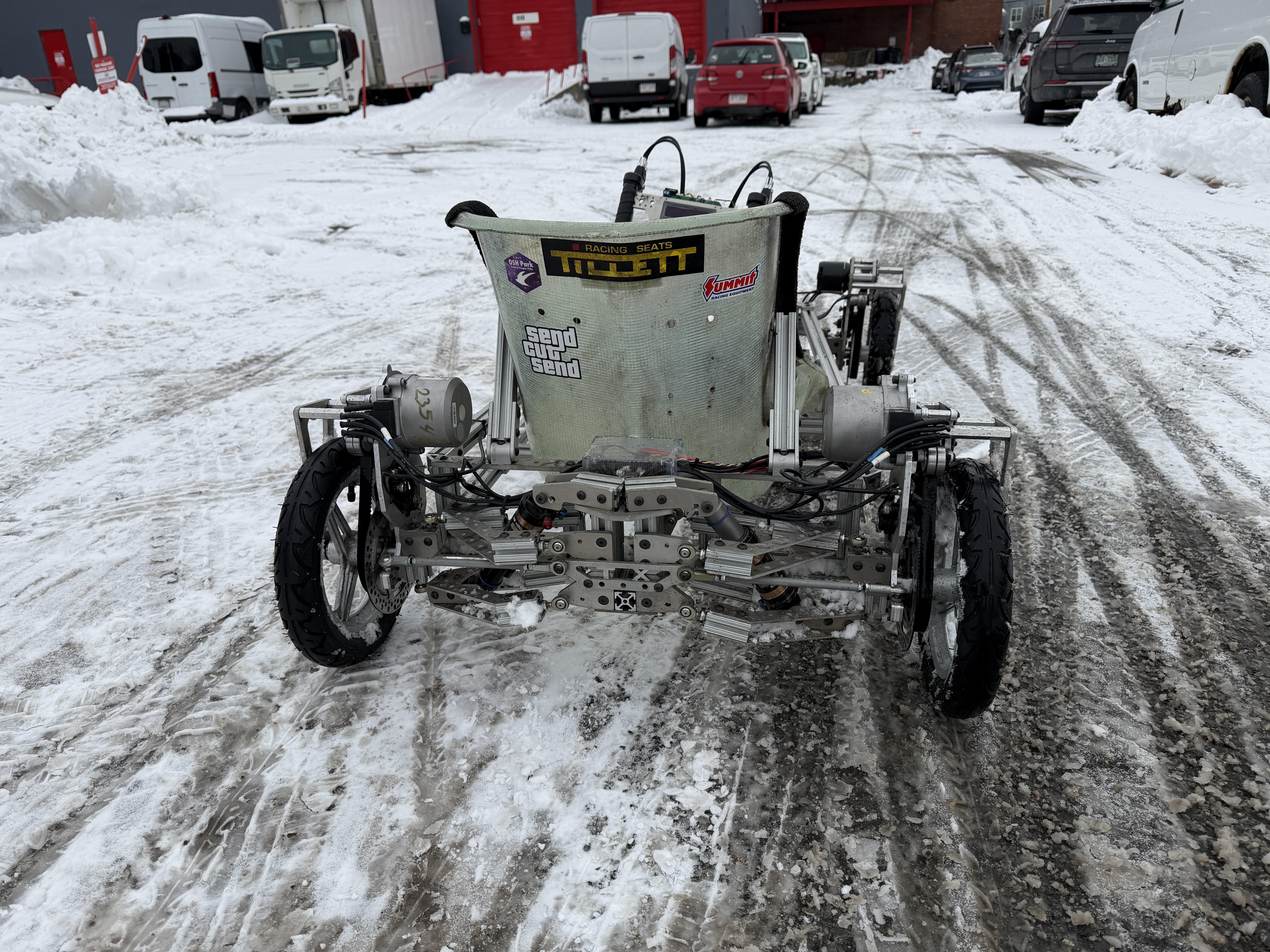
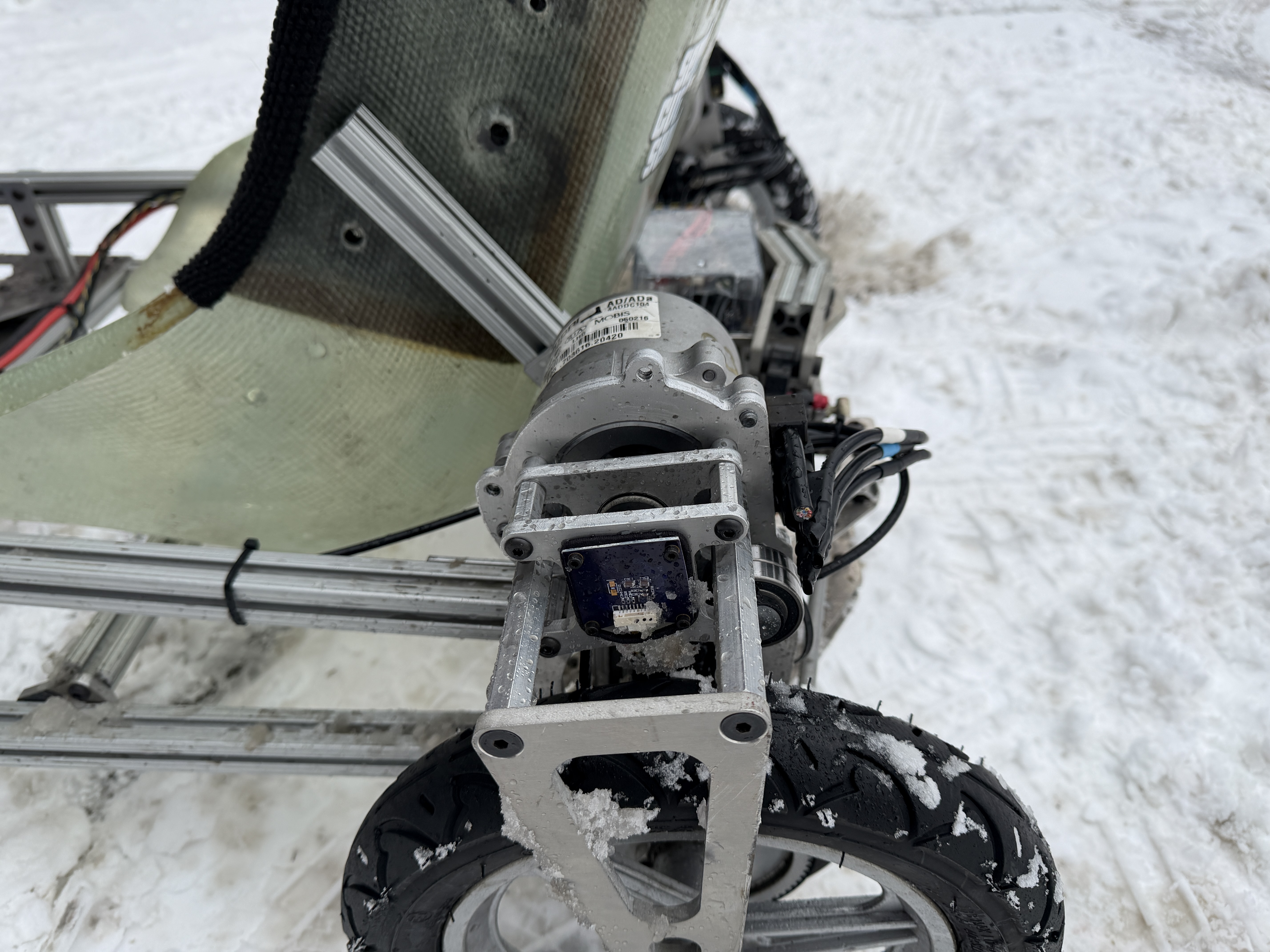
The sensor board conformal coating is holding up, somehow.

At 80-100A, the Hyundai EPS motors feel pretty much identical to the APS 6374 170KV. They can easily generate and control oversteer on the snow. And after half a battery pack of messing around, they were staying nice and cool. So I think they do have some overhead now, if I want to push even more current in dry conditions. The main problem will be the suspension:

The A-arm flex is not good, even at 100A. At first glance, it seems like most of the displacement is originating from the two quarter-inch aluminum plates that hold the rear ball joints. They're only flexing a little, but that angular offset creates a lot of displacement at the plane of the wheel. Luckily, it's easy to reinforce these - just add even more 80/20:
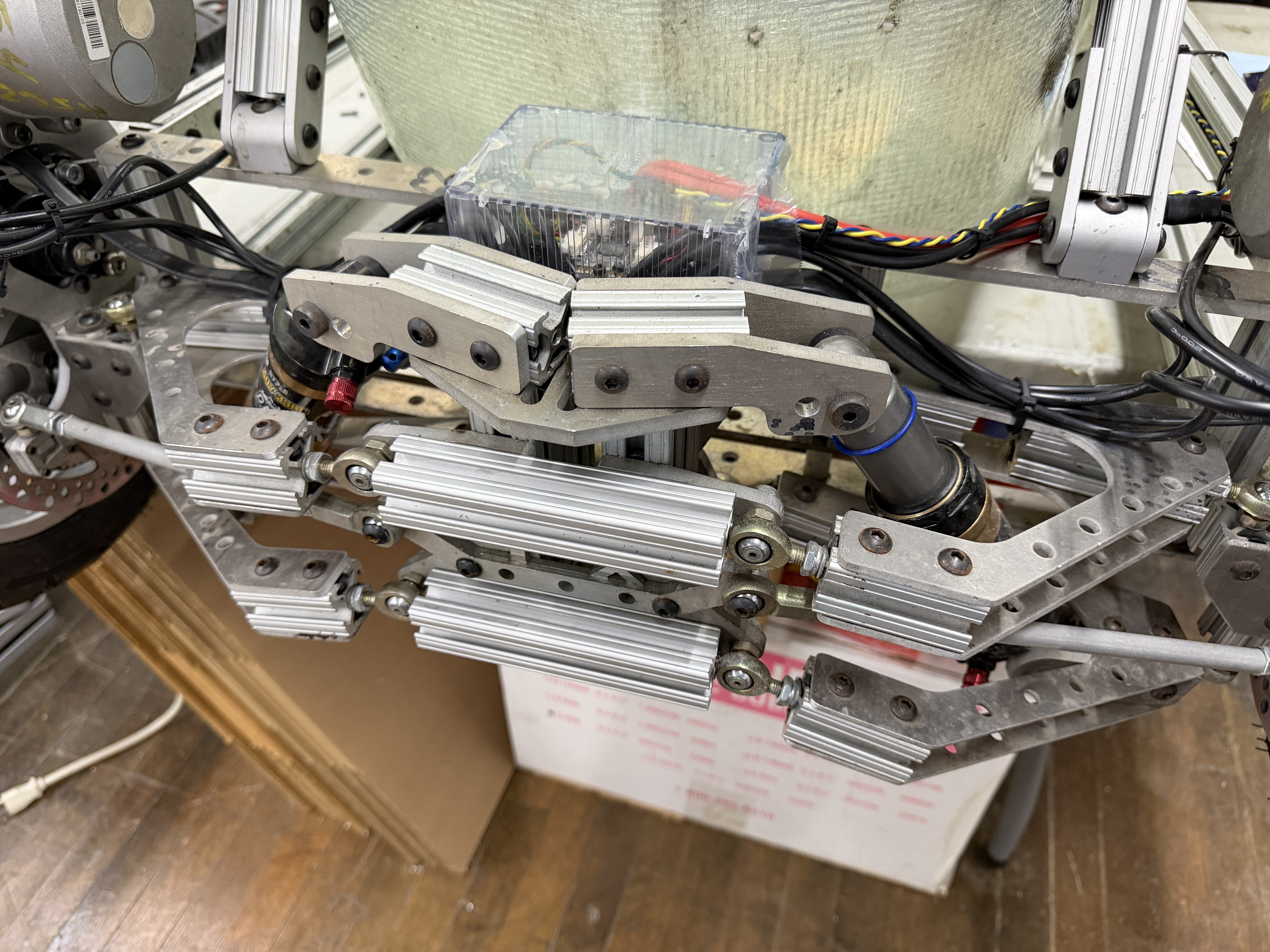
I'm sure there's an even lighter way to do this, but it actually looks like it belongs. It also gives some new mounting points for accessories, cameras, etc. I will add one to the front as well. Only the top is needed there; the steering linkage bearing plate handles the bottom. Of course, these are even more weight that I now need to offset to get it back under 40kg.

But for now, I think this upgrade is complete. I still need to test the motors at speed when (if) the snow ever melts. They do have higher inductance than the APS 6374 170KV, which might limit their maximum power. They're also designed for 12V, not 48V, so they might lose efficiency at higher speeds due to speed-squared losses. I'll have to do some data logging to find out.

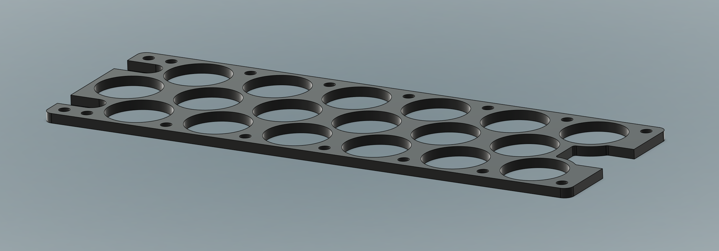
The next upgrade is also in the works...here's a teaser:
Sunday, September 12, 2021

TinyCross: New UI and Front Wheel Traction Control

 In the last post, I finally did some actual data logging with TinyCross set up in 4WD, 80A peak per motor, which is the rated current. Based on tinyKart, I know they can handle a a bit more for short durations, maybe even up to 120A. But the data logs (and many instances of having rocks flung into my face) demonstrate that the front wheels reach their traction limit somewhere around 60A on asphalt.

The behavior of front wheel slip on a go-kart is something new to me. In a straight line, the initiation of the slip and the acceleration of the wheel actually isn't the biggest problem. It's when the wheel regains traction and slows down that bad things happen. The restored grip combines with the energy being dumped from the wheel's moment of inertia to generate a quick pulse of torque on that side, which creates a lot of torque steer.

To deal with this, I wanted to implement some form of traction control, at least for the front wheels, so that I could get the most torque out of them as possible without the steering disturbances and rock shooting. But first, I needed a way to easily configure both the motor currents and the traction control settings without having to drag around my laptop everywhere. So, I finally built out the steering wheel UI to include a bunch of settings:

Sorry for the exposure; it's the only way to capture the full OLED refresh period.

Anyone familiar with the MōVI Controller might recognize the OLED display. I chose this for daylight visibility and responsiveness (~50Hz update rate). The menu interface is essentially the same as the one I built the day before NAB 2014... The left knob scrolls through the menu. The right knob adjust settings and, by clicking or holding, performs actions.

In the four corners are three motor parameters for the corresponding motors: S for Status, which shows error codes. F for Forward peak current, and R for Reverse (braking, or actually reversing) peak current. Setting both to zero masks out the CAN command from that motor, triggering a timeout that turns off the gate drivers entirely. A click and hold on S triggers an encoder recalibration for that motor.

In the second column from the left, the first three settings relate to data logging: LS for Logger Status, FN for File Number (click to start a new file), and LT for Logger Time, the time in [ms] for a single row of the data log to be written. Then, there are two parameters for tuning traction control: TT for Traction Threshold, and TG for Traction Gain, which I will explain shortly.

The reason I wanted to be able to adjust peak currents from the steering wheel is because I agree with this early Tesla blog post: "...it's much safer to avoid wheelspin altogether than react to it." If I know the surface supports front wheel current around 60A, there's not much point in setting it higher than that. But, I want to be able to set it higher for testing, or adjust it for different surfaces.

As for the traction control itself, there are a lot of corner cases to think about in 4WD, but the main problem I'm trying to solve is front wheel slip. If I assume the rear wheels are not slipping, then I can use their average speed as a reference. From there, it's easy to see if a front wheels is running faster than that reference, and reduce the current to that motor if so. This only needs two settings: a Traction Threshold (TT) that sets how much wheel slip is allowed, and a Traction Gain (TG) that sets how much to reduce the current per unit slip above the threshold. The Traction Threshold prevents overactuation in normal conditions and allows for speed differential due to turning radius.

But what happens if a rear wheel does slip? Well, then the front wheel might slip too. At that point, I'm probably in some kind of a four wheel sideways drift anyway, so alternate control laws are going to apply. Being able to trigger some rear wheel slip with the throttle is part of the fun, too, so having complete 4WD traction control isn't something I necessarily need to solve.

With the new UI setup and the simple front wheel traction control in place, it was time to do some tuning...

...or not.

At first, everything seemed to be going okay. I did a couple of runs at 60A front current and 80A rear current and the traction control seemed to be working as intended. But then during light regenerative braking at around 30mph, I heard the all-too-familiar sound of a FET popping, followed by some more bad noises and smells from the front drive. Upon inspection, only two FETs actually died, but they also took out many of the power traces, meaning this board was trash.

So what happened? Well, unfortunately, the data log was not very helpful in this case. It did show the speed (30mph) and current command (around -10A), but nothing out of the ordinary up until the point of failure. There is only one data point showing a Q-Axis current of 286A on the front left motor, followed by an undervoltage fault, which might have been the battery sagging or the power input traces getting blown up. So whatever happened, happened quick.

It's been a while since I've actually destroyed a motor controller, so I was a little disappointed. But after some thought, I didn't think this was due to the new traction control stuff. That's only applied during acceleration, and this failure definitely happened under braking. I think it's more likely that the front left motor just lost sync and the back EMF at 30mph was high enough to do damage. Up until now, I have only had a relatively slow overcurrent limit of 160A (or more) for 10ms. These FETs have a pretty insane Safe Operating Area (SOA), but that limit does leave room for exceeding it with currents above 400A:

This system could easily generate a 400A transient if a motor loses sync at 30mph. And the motor position and speed data does cut out at the same data point as the failure. But that's not enough to determine cause and effect. So for now I can only make changes that might help and hope for the best. I added in several more stages of faster overcurrent protection, up to 300A for a single ADC/PWM cycle (42.7μs). These overlap enough to cover the entire R_DS(on)-limited boundary of the SOA (up to the pulse rating of 1450A for 100μs!).

A faster overcurrent trip doesn't help with whatever caused the motor to lose sync in the first place (if that is what happened). I have seen at least a couple previous instances where the encoders, which supply emulated Hall effect sensor signals, have behaved as if they were completely reset. Even though I only use the buffered and optically isolated virtual Hall effect sensor signals for commutation, I was still reading the SPI data anyway. Maybe a SPI read got corrupted by noise and turned into a write that either reconfigured or entirely reset the encoder mid-run? To protect against this, I now disabled the SPI transactions entirely other than during initialization and calibration.

So with these changes and my last and only spare drive, I went back out for another try. This time, I ran into no motor drive issues and was actually able to test and tune the front wheel traction control as I originally intended. The difference is immediately obvious while driving and in the data. First, a test at 80A front, 90A rear, with no traction control:

Front wheel traction control off.

As before, the front right wheel starts slipping at about 60A and spins up to 2-3x the actual ground speed. The front right always seems to lose grip first, a mystery to solve another day. When I let off the throttle and it regains traction, the torque pulse creates substantial torque steer, jerking the steering wheel almost 20º to the left, which I then have to counteract immediately to stay on course. Overall, it's impossible to sustain peak acceleration for more than a second or so before having to deal with the wheel spin and torque steer.

And now with the same currents, but front wheel traction control on:

Front wheel traction control on.

The front right (FR) current now averages a bit below 60A and its speed is held to just a small margin above the actual ground speed. It's never able to build up momentum and then "catch", inducing torque steer. This allows continuous acceleration up to and past 30mph. The front left (FL) also starts to slip in the 20-30mph range, but the traction control catches it too. The overall result is a much more controllable launch and far fewer rocks being thrown up by the front wheels.

After finding traction control settings that I liked, I switched back to current settings that more closely match the actual traction limits: 60A front and 100A rear. This still gives a reasonable 0.45g launch, but with less likelihood of triggering the traction control on asphalt. I'd like to push to >0.5g, to match tinyKart's most extreme configuration, but that'll either require 120A on the rear or changing the gear ratio a bit. At 60A / 100A, the front motors still share enough of the load that the rear motors stay at healthy temperature after some acceleration runs:

Rear motors are doing most of the work, but...

...they are at a reasonable temperature.

And finally I did some less structured testing by just driving through the gravel corner in my parking lot and intentionally adding throttle to induce slip. It behaves pretty well, slipping and oversteering about the right amount to be controllable but still fun:


I think at this point most of the handling bottlenecks are back on the mechanical side. There's a small amount of backlash in the steering column that definitely exaggerates the residual torque steer, especially at high speeds. It's almost all coming from the U-joint, which I may try to shim or replace with one with tighter tolerances. Other than that, I need to do some suspension geometry tweaking to improve handling of lateral transients. Speaking of which, here's one last data capture. See if you can figure out what's going on here...

Mystery data log.

Sunday, August 15, 2021

TinyCross: 4WD 80A Data Logging

It's been a long time since I did a proper test drive with TinyCross, although I've taken it out just for fun a few times. Since I completed the weight/width reduction pass last week, I wanted to get it out again and do some proper data logging in 4WD, with the peak current set to 80A for all four motors. This is still below the ultimate target of 100-120A (for short bursts), but plenty for parking lot testing.

Really enjoying the extra 2" of clearance - I can get through most of the "doors" in my building now.

I had to inflate the tires, but amazingly the air shocks don't seem to have leaked at all after a year of neglect. And they still do a pretty impressive job of soaking up the awful topography of my parking lot.

I wanted to do some more thorough data logging in 4WD to characterize some of the issues I've felt while just driving around for fun. The steering wheel PCB collects data from the front and rear motor drives over CAN, appends some of its own data, and writes the whole thing to a microSD card. When I first set this up, I just had it overwrite the existing data log every power cycle. But in the couple of years since I set that up, I've had to master FatFs. So setting it up to create new files on the fly without messing up any of the real-time stuff was an easy upgrade.

Here's what a 4x80A launch looks like:

4x80A launch (attempt).

The main problem is pretty obvious from the data: the front wheels just don't have enough weight on them to support 80A. If there's even a little bit of a loose surface, one or both front wheels will lose grip. Excessive wheel slip is inefficient, so the peak acceleration isn't as high as it could be if all four wheels hugged their grip limit. But front wheel slip is especially bad because it results in massive torque steer. (I actually used this to make remote-control TinyCross.) It also has a habit of throwing rocks up into the driver's face.

I've even debated whether the front wheel drive on TinyCross is worth the extra weight and complexity. tinyKart handled pretty well with RWD only: I could put in a controlled amount of oversteer with the throttle. In fact, I got a chance to test out how TinyCross feels with RWD only when I had - let's call it an 80/20 failure - on the front right upright:

Always check your T-nuts! The only real casualty was the encoder wire.

Although I was able to fix the mechanicals with the single hex driver I always bring with me, a few crimps pulled out of the encoder wire and I didn't have the tools to fix it. I could probably add a failover to sensorless operation for individual motors, but I'm not sure how well it'd work on the front motors, again because of torque steer. (Both fronts would have to agree to not produce torque until the flux estimator converges on the sensorless motor.) For now, I just removed power from the front drive.

In terms of handling, RWD works fine. But the launch is a mere 0.25g at 2x80A. There's no slip, and even if there was, it wouldn't matter as much on the rear since it doesn't induce torque steer.

2x80A launch.

Even at 120A, this would only be about a 0.4g launch. tinyKart, in its last and somewhat scary configuration, was hitting about 0.5-0.6g. Part of this is down to gearing: TinyCross, with 12.5" wheel, has to be geared for higher speeds. I could always ditch the front motors and switch to 80mm motors with more torque on the rear. But I think that goes against the spirit of TinyCross. Having full independent suspension and 4WD has always been the point.

So I think I'll finally have to dive in to writing some simple traction/launch control software. Just looking at the 4x80A launch data, it's easy to pick out the wheel that's slipping and imagine that the software could just fold back the current command to that wheel as its speed starts to diverge from the other three. But there are so many logical knots on the path to generalizing that to 4WD, where any subset of the four wheels could be slipping, that it makes my brain hurt to even think about.

There are some amazing technical blog posts from the early days of Tesla (back when it was more of an engineering project than a consumer electronics device) where they talk about how it took months to go from a controller with excellent high-bandwidth torque control to functioning traction control, and even then a lot of it was subjective. One observation I really liked:

This type of feedforward traction control can be hugely beneficial; for instance, it's much safer to avoid wheelspin altogether than react to it.

This was regarding a lateral G observer that was fed into the friction model that the traction control software used to help limit motor torque to what it thought the tires could reasonably handle. This way, wheel slip might be limited to cases where there truly is a sudden drop in friction at one wheel. I think that should be the goal for this as well. I might even be able to just do slip detection on the front wheels. It'll be an interesting experiment, at least.

Saturday, August 7, 2021

TinyCross Weight and Width Reduction Pass

It's summer, which means it's time to work on go-karts. This round, it's a modification to TinyCross that I've been wanting to make ever since I first got it together about two years ago. The main issue is that I designed it around stock rear 12.5" scooter wheels. These are almost symmetric and have threading on both sides of the hub that are meant for mounting the drive sprocket and brake disk. But - and this is maybe my favorite bit of packaging on this project - I've got the brake and drive sprocket both mounted to the inboard side, with the brake caliper sitting right in the middle of the belt:

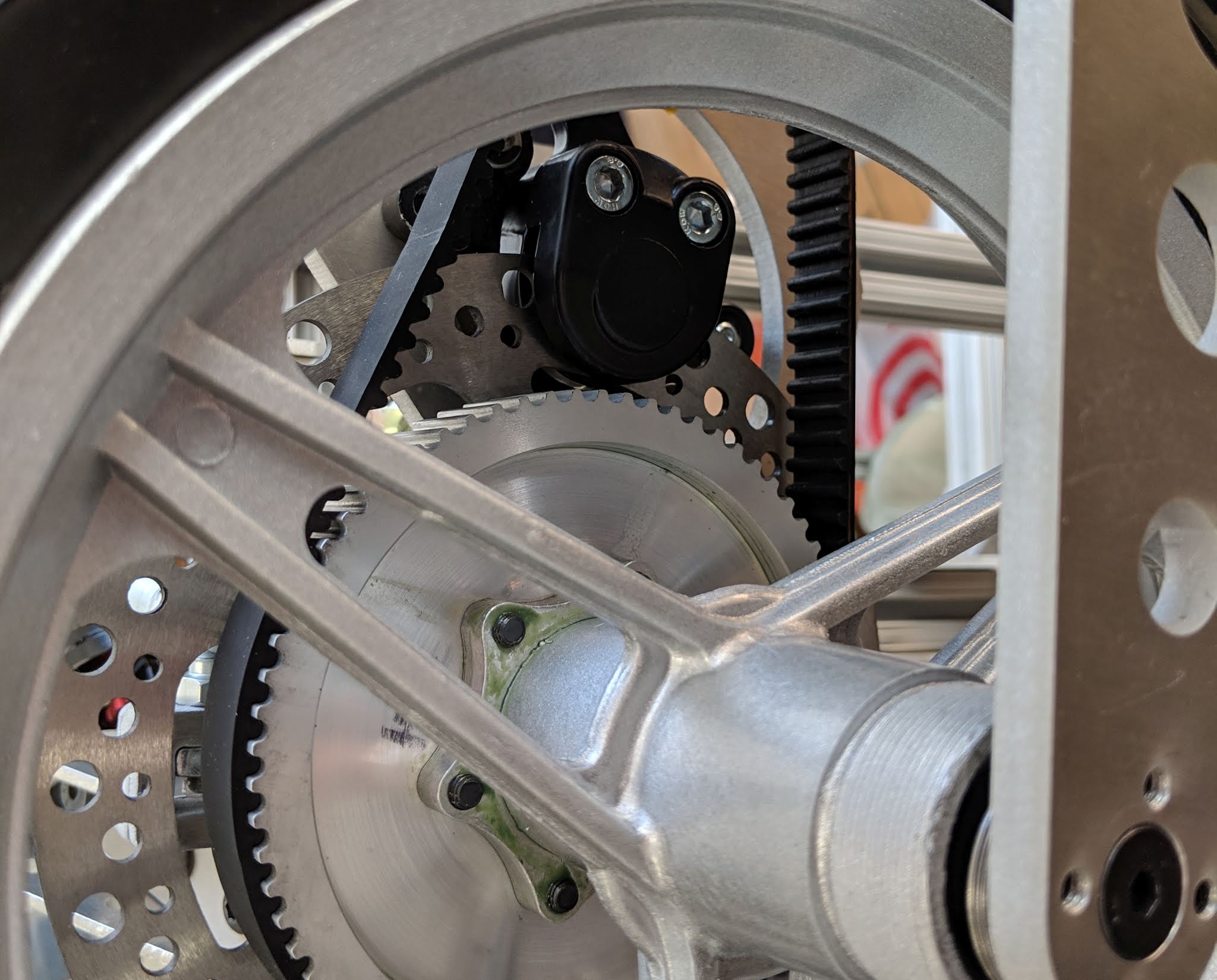
The brake and drive sprocket are both mounted to the inboard side of the wheel, making the outboard side of the hub dead weight.

This makes the extended length of the outboard side of the hub useless. But, I left it as stock for simplicity. I figured if I ever needed to replace the wheels, it would be easier to drop in a new stock 12.5" wheel. But, this drives the overall width of the kart up to about 35" for no good reason:

The total width, about 35", is driven in part by the symmetric 12.5" wheel hubs.

It's also unnecessary weight, especially factoring in the beefier 5"x5/8" hex standoffs I used to close the structural loop around each wheel. I figured I could eliminate 2" off the total width and about 1lb off the total weight if I just bit the bullet and re-machined the 12.5" wheel hubs. It still wouldn't fit through a 32" door frame, but it would be easier to wiggle through indoor spaces and fit in my car. It also would just look a lot nicer.

One of the reasons I put off this modification for so long is because I thought it would involve disassembling the entire wheel module, but it turns out that it's just barely possible to remove the wheel without removing the motor. I can take off the brake caliper and slip the belt off the pulley to give it just enough slack to pull the wheel off the spindle shaft. I don't remember intentionally designing it this way, but let's pretend I did. It'll be good for fixing flats, too. 

The next obstacle to overcome was removing the outboard bearings. I didn't have a bearing puller on-hand, but I discovered that an 80/20 T-Nut (which I obviously have hundreds of...) is just about exactly the right size to push on the outer race of these bearings. So I came up with this improvised tool:

Improvised bearing pusher.

The tool is built inside the hub by slipping the 80/20 T-Nut through the bearing, flipping it horizontal, then dropping in the hex standoff from the other side. After fastening it together with a 1/4-20, it's ready for the press. Luckily, I didn't Loctite these bearings in, so they pressed out pretty easily.

Pressing out the bearings using the makeshift pusher.

The 12.5" wheels don't fit on my mini lathe, but they do just barely fit on my mini-mill. I knew this ahead of time, so I bought a 22mm end mill specifically for cutting the new bearing pocket. (One of the nice features of this mini-mill is its use of a regular R8 spindle, so it's possible to get large tools for it.) I did have to get a little creative with fixturing. The brake disk is bolted down to a piece of 80/20, which is clamped in the mill. But, to make things stiff enough, I also had to ground the rim itself directly to the bed with some long clamping screws.

Clamping situation: not great, not terrible.

Pretty sure this mill was never meant to hold a tool this big.

I decided to extend the bearing pocket by 1.000" first, before machining down the hub by 1.000". I'm not sure if this was the best order of operations, but it all went pretty smoothly. Here's 7:45 of relaxing slow-motion bearing pocket cutting, captured at 4K 420fps with my Wave:

These hubs are cast aluminum, so it wasn't surprising to find that there were some voids in the newly-machined faces. They're nothing that I think would affect the structural integrity, but it's an interesting consequence of the manufacturing process.

Casting voids exposed by re-machining the hubs.

One of the downsides of doing this operation on the mill is that I didn't have a choice of machining the new bearing pocket to an interference fit. But I was pleased to see that, with all the extra effort put into stiffening the fixture, it was still a nice slip fit. I can always add Loctite later if needed.

After re-machining, the bearings are now a nice slip fit.

That just leaves the 7075 spindle shafts, which also needed to be shortened by 1.000". Cutting off the extra length and extending the outboard mounting hole was a quick task for the mini-lathe. Then, it just needed to be re-tapped.

Shortening the 7075 spindle shafts...

...and re-tapping.

Finally, I put everything back together, substituting much lighter 4"x1/2" hex standoffs to span the gap at the top of each wheel module. The total process took only about two hours per wheel, including disassembly and reassembly. So something I have put off for two years was really only one day of work...typical. Anyway, the final result is a kart that's now 2" narrower and about 1lb lighter.

The pile at the front is roughly the weight saved. (5"x5/8" standoffs were replaced by 4"x1/2", but an equivalent amount of weight was taken out of each hub.)

I have a few more tasks I want to do on this kart. It still needs to be fully weather-proofed. I have a plan for enclosing the motor drives, but need to figure out something for the steering wheel PCB. I may redesign that board from scratch since I don't think I'll ever get to using the battery balancing circuit on it. It can be much smaller and simpler without that. Lastly, there's always motor drive stuff to fiddle with to squeeze out more torque and/or speed.

For now, though, I'm glad it's a little lighter and a lot narrower. It'll make deploy that much easier, which ultimately means more actual testing and use.

Monday, November 11, 2019

TinyCross: 4WD and Servoless RC Mode

I finished building up the second dual motor drive for TinyCross, which means that the electronics and wiring have finally caught up to the mechanical build and both are 100% complete!


That's not to say that the project is 100% complete; there's still some testing to be done to bring it all the way up to full power, as well as some weight reduction and weatherproofing tasks. But there are no more parts sitting in bins waiting for installation. It should be at peak mass, too, which is good because it's 86lb (39kg) without batteries. The original target was 75lb (34kg) without batteries, but I will settle for 80lbs (36kg) if I can get there.

The second TxDrive went together with no issues, and the software is identical to the front wheel drive. I have both set at 80A right now, which gives a total force at the ground of 112lbf (51kgf). That's about the same peak force as the rebuilt "black" version of tinyKart, which was maybe too much for that frame. But TinyCross is about 20% heavier (with the driver weight included) and 4WD, so it should be able to handle some more. I haven't seen any thermal issues at 4x80A - if anything, the motors run cooler now that all four are sharing the acceleration. Over the next few test drives, I'll work my way up toward the 120A target.

But before that, there's something I've been wanting to try. I have an abundance of actuators and not that many degrees of freedom. I decided to borrow an idea from Twitch X to cash in some of this actuator surplus for one more degree of control, specifically automatic servoless steering. So, a free 1/3-scale RC car mode without adding any parts.

Well okay, I do have to add the receiver.
The steering wheel board reads the throttle and steering PWM signals from a normal RC receiver. The throttle PWM gets directly mapped to a torque command for all four motors. The steering PWM sets a target angle for the steering wheel. The measured angle comes from an IMU, the secret part on the steering wheel board. (Yes, there are all sorts of issues with that...I honestly just don't want to run any more wires.) The angle error drives a feedback controller that outputs differential torque commands to the front motors. Not much to it, really.
I've also seen so many runaway robots and go-karts in my life that I consider it a must to have working failsafes for both radio loss of signal and receiver (PWM) disconnect. It's extra work but trust me, it's worth it! Anyway, time for a test drive:


I wasn't sure how tightly I could tune the steering control loop, since there's a long chain of mechanical mush between the torque output at the motors and the sensor input at the steering wheel. But it works just fine. After a minute I forgot it wasn't really an RC car and tried some curb jumping. Just like Twitch X, the wheels do need traction to be able to control the steering angle. But then again, that is a necessary condition for steering anyway.

I don't actually think there's much point in a go-kart-sized RC car. But it's a short jump from that to an autonomous platform. It might also be useful to adjust the "feel" of the steering during normal driving. Mostly, I just like to abide by the Twitch X philosophy of using your existing actuators to do as much as possible.

Tuesday, September 24, 2019

TinyCross: First Test Drive and Synchronous Data Logging

With the front wheel drive complete and the steering wheel control board working, it's finally time for a first test drive:


I've been waiting over a year to see if this mountain bike air shock suspension setup would work, and it looks like it does! I haven't done any tuning on it besides setting the preload, but it handles my pretty beat up parking lot nicely, absorbing bumps that would have broken tinyKart in minutes. The steering linkage also seems okay, with good travel and minimal bump steer. There are still some minor mechanical improvements I want to make, but it's nice to see the suspension concept in action after all this time.

I started with front wheel drive so I could see if the motor drive had any Flame Emitting Transistors, but happily it did not. It's the same gate drive design that I use on everything and it always just works, so I shouldn't be surprised anymore. But I am asking a lot of the FDMT80080DC FETs (just one per leg), so I'm working my way up to 120A (peak, line-to-neutral) phase current incrementally. The above test is at 80A and the FETs seem happy, although the motors do get pretty warm already. They might need some i²t thermal protection to handle 120A peaks.

Synchronous Data Logging

One of the early lessons I learned in building motor drives is to always log data. Nothing ever works perfectly on the first try, but having data logging built in from the start is the best way I know of to quickly diagnose problems. A lot of the stuff that happens in a motor drive is faster than typical data logging can capture, but a lot of it is also periodic. By synchronizing the data collected to the rotor electrical angle, its possible to reveal detailed periodic signals even with relatively low frequency (50Hz) logging to an SD card. As a quick example, here's a standard data logger plot of motor phase currents over time:
Phase current vs. time, pretty boring.
This type of plot shows the drive cycle, with periods of high current during acceleration (or braking) and periods of near zero current when coasting or stopped. And it shows that phase currents sometimes exceed 100A even with an 80A command. But a plot of Q-axis (torque-producing) current, which is already synchronous, could give a better summary of this information. The time resolution (40ms) isn't fine enough to show the AC signals.

However, each set of three phase currents is also stamped with a rotor electrical angle measured at the same time (within about 10 microseconds). Cross-plotting the phase currents against their angle stamp, instead of against time, reveals a much more interesting view of the data:
Same data, different meaning.
Now it's possible to see the three phase current waveforms separated by 120edeg. The peaks are at 0º (Phase A), 120º (Phase B), and -120º (Phase C). There are also negative peaks at the same angles, where braking is occurring. Most interestingly, the shape of the current waveforms at 80A peak is revealed to be asymmetric and far from sinusoidal.

The angular resolution of this type of waveform capture is only limited by the angle measurement, regardless of logging frequency. By contrast, the fastest it would be possible to log a continuous waveform would be at the PWM frequency (23.4kHz, in this case), which gives an speed-dependent angular resolution of 11.3edeg per 1000rpm. It would become difficult to resolve the shape of the current waveform at high speeds. There's always a trade-off, though: Synchronizing low-speed log data with angle stamps is only able to show the average shape of long-term periodic signals. It would not catch a glitch in a single cycle of the phase currents.

While the phase current shape is interesting, the position of the peaks is just a consequence of the current controller. Zero electrical degrees is defined (by me, arbitrarily) as the angle at which Phase A's back EMF is at a peak. The current controller aligns the Phase A current with the Phase A back EMF for maximum torque per amp. So the phase current plot shows that the current controller is doing its job. This information is also captured by the already-synchronous Q-axis and D-axis current signals:

Q-axis and D-axis current plotted against time.
The Q-axis current represents torque-producing current, aligned with the back EMF, and is the current being commanded by the throttle input. The D-axis current is field-augmenting (or weakening, if negative) current and doesn't contribute to torque production. In this case, the current controller seeks to hit the desired Q-axis current and keep the D-axis current at zero. It does this by varying the voltage vector applied to the motor. More on this later. The Q-axis and D-axis currents are rotor-synchronous values, so they already convey the magnitude and phase of the phase currents, just not the actual shape.

All of this is based on the assumption that the measured rotor angle is correct, i.e. properly defined with respect to the permanent magnets. On this kart, I'm using magnetic rotary sensors mounted to the motor shafts that communicate the rotor angle to the motor controller via SPI and optically-isolated emulated Hall sensor signals. But it's also possible to measure the rotor angle with a flux observer, as long as the motor is spinning sufficiently fast. I have this running in the background, logging flux estimates for each phase.

Again, plotting flux against time doesn't give a whole lot of information. It's interesting to see the observer converge as speed increases from zero at the start, and the average amplitude of about 5mWb is consistent with the motor's rpm/V constant and measured back-EMF. But the real value of this data comes from cross-plotting against the sensor-derived rotor angle:
Cross-plotting against sensor-derived electrical angle shows substantial offset between the two motors.
The flux from Phase A should cross zero when its back EMF is at its peak, i.e. at an electrical angle of 0º in my arbitrarily-defined system. So, the front-right motor is more correct. The front-left is offset by about 30-45edeg, which is enough to start causing significant differences in torque. Indeed I had noticed some torque steer during the first test drives, which is what prompted me to do the sensor/sensorless angle comparison in the first place.

Since I have all three phases of flux, I can estimate the flux vector angle with some math and compare it to the sensor-derived rotor angle:

Digging into flux angle offset of the front-left motor a little more.
Both motors have some variation in flux angle offset, but the front-left varies more and is further from the nominal 90º. Except...when it's not. There are two five-second intervals where the average offset of the front-left flux looks like it returns to nearly 90º, both occurring either during or just after applying negative current. However, there's one more negative current pulse, earlier in the test drive, that does not have a flux angle shift. My troubleshooting neural network has been trained over many project iterations to interpret this as the signature of a mechanical problem.

Sure enough, I was able to grab the rotor of the front-left motor and twist with hand strength only (< 5Nm) enough to make the shaft move relative to the rotor can. It only moved about 5º, but that's 35edeg, which is about the offset I had been seeing in the data. The press fit had failed and it was relying on back-up set screws on flats to keep from completely slipping. I suspect this won't be the last motor to fail in this way. I pressed out the shaft, roughed up the surface a little, and pressed it back in with some Loctite 609. I also drilled a hole in the back that can potentially be tapped as a back-up plan. And finally I recalibrated everything and marked the shaft so I'll know if it slips again.

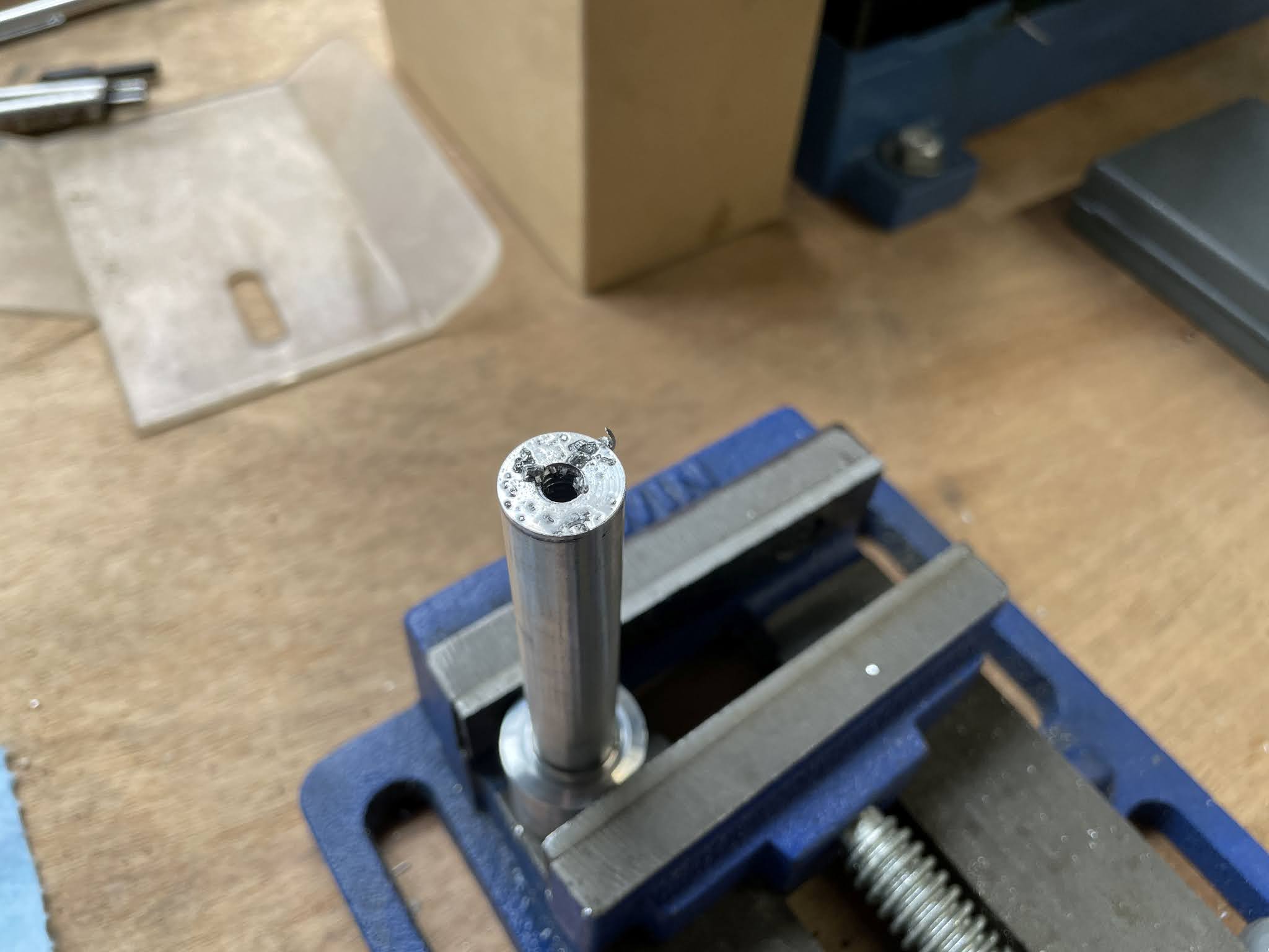
Reworked shaft, with a 1/4-20 tap drill (not going to tap it unless I absolutely have to), roughed surface, and press-fit augmented with Loctite 609, which should be good up to 25Nm for this surface area (4-5x margin).
After a few more test drives, it looks like it's holding. The front-left flux vs. sensor-derived angle looks much closer to the correct phase as well:

Phase A flux vs. sensor-derived angle after shaft rework.
There's still a +/-10edeg offset from nominal, which could be from calibration accuracy or static biases like normal shaft twisting. It might be worth investigating more, but it's not enough offset to create any noticeable torque steer on the front wheel drive, so I'm satisfied for now. I will preemptively do the same rework on the remaining three motor shafts.

One other interesting cross-plot to look at is the Q- and D-axis voltage as a function of speed. I mentioned above that the current controller attempts to align the current vector with the back EMF vector by manipulating the voltage vector, the basis of field-oriented control. Due to the electrical time constant (L/R) of the motor, the voltage must lead the back EMF by a varying amount. This shows up as negative D-axis voltage increasing in magnitude with speed (and current).

Jitter 3D  plot of the voltage vector operating curve.
At 80A and 2500erad/s (~3400rpm and ~27mph), the voltage vector is already leading by 45º, with 12V on both axes. This gives me a rough estimate for the motor's synchronous inductance.
Along with the measured resistance (32mΩ) and flux amplitude (5mWb), this is all that's required for a first-order motor model, and thus a torque-speed curve. Running this through the gear ratio, the force-speed curve at the ground should look something like:


The inductance has a large impact on the maximum speed at which 120A can be driven into the motor in-phase with the back EMF. This determines the maximum power, since above this speed the force drops off faster than the speed increases. The top speed is wherever on the curve the drag forces equal the motor force, probably in the 40-45mph range. This is all without using third harmonic injection, which gives an extra 15% voltage overhead (for the cost of higher peak battery power, of course). If I do turn that on, it will probably come with a gear ratio change to put that extra 15% toward more torque, not more speed.

That's all I wanted to check before building up the second motor controller for the rear wheel drive. I'm very eager to see how it handles with 4WD, and how close to this force-speed curve I can actually get.