
It's summer, which means it's time to work on go-karts. This round, it's a modification to TinyCross that I've been wanting to make ever since I first got it together about two years ago. The main issue is that I designed it around stock rear 12.5" scooter wheels. These are almost symmetric and have threading on both sides of the hub that are meant for mounting the drive sprocket and brake disk. But - and this is maybe my favorite bit of packaging on this project - I've got the brake and drive sprocket both mounted to the inboard side, with the brake caliper sitting right in the middle of the belt:
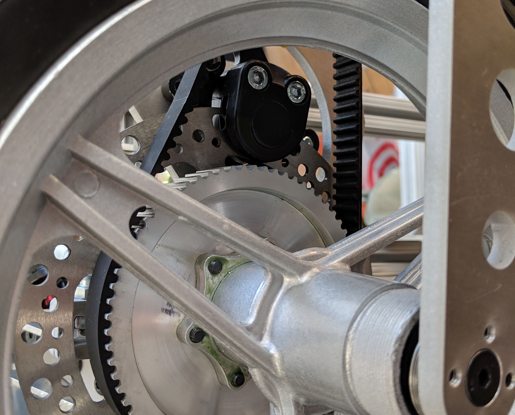 |
| The brake and drive sprocket are both mounted to the inboard side of the wheel, making the outboard side of the hub dead weight. |
This makes the extended length of the outboard side of the hub useless. But, I left it as stock for simplicity. I figured if I ever needed to replace the wheels, it would be easier to drop in a new stock 12.5" wheel. But, this drives the overall width of the kart up to about 35" for no good reason:
 |
| The total width, about 35", is driven in part by the symmetric 12.5" wheel hubs. |
It's also unnecessary weight, especially factoring in the beefier 5"x5/8" hex standoffs I used to close the structural loop around each wheel. I figured I could eliminate 2" off the total width and about 1lb off the total weight if I just bit the bullet and re-machined the 12.5" wheel hubs. It still wouldn't fit through a 32" door frame, but it would be easier to wiggle through indoor spaces and fit in my car. It also would just look a lot nicer.
One of the reasons I put off this modification for so long is because I thought it would involve disassembling the entire wheel module, but it turns out that it's just barely possible to remove the wheel without removing the motor. I can take off the brake caliper and slip the belt off the pulley to give it just enough slack to pull the wheel off the spindle shaft. I don't remember intentionally designing it this way, but let's pretend I did. It'll be good for fixing flats, too.
The next obstacle to overcome was removing the outboard bearings. I didn't have a bearing puller on-hand, but I discovered that an 80/20 T-Nut (which I obviously have hundreds of...) is just about exactly the right size to push on the outer race of these bearings. So I came up with this improvised tool:
 |
| Improvised bearing pusher. |
The tool is built inside the hub by slipping the 80/20 T-Nut through the bearing, flipping it horizontal, then dropping in the hex standoff from the other side. After fastening it together with a 1/4-20, it's ready for the press. Luckily, I didn't Loctite these bearings in, so they pressed out pretty easily.
 |
| Pressing out the bearings using the makeshift pusher. |
The 12.5" wheels don't fit on my mini lathe, but they do just barely fit on my mini-mill. I knew this ahead of time, so I bought a 22mm end mill specifically for cutting the new bearing pocket. (One of the nice features of this mini-mill is its use of a regular R8 spindle, so it's possible to get large tools for it.) I did have to get a little creative with fixturing. The brake disk is bolted down to a piece of 80/20, which is clamped in the mill. But, to make things stiff enough, I also had to ground the rim itself directly to the bed with some long clamping screws.
 |
| Clamping situation: not great, not terrible. |
 |
| Pretty sure this mill was never meant to hold a tool this big. |
I decided to extend the bearing pocket by 1.000" first, before machining down the hub by 1.000". I'm not sure if this was the best order of operations, but it all went pretty smoothly. Here's 7:45 of relaxing slow-motion bearing pocket cutting, captured at 4K 420fps with my Wave:
These hubs are cast aluminum, so it wasn't surprising to find that there were some voids in the newly-machined faces. They're nothing that I think would affect the structural integrity, but it's an interesting consequence of the manufacturing process.
 |
| Casting voids exposed by re-machining the hubs. |
One of the downsides of doing this operation on the mill is that I didn't have a choice of machining the new bearing pocket to an interference fit. But I was pleased to see that, with all the extra effort put into stiffening the fixture, it was still a nice slip fit. I can always add Loctite later if needed.
 |
| After re-machining, the bearings are now a nice slip fit. |
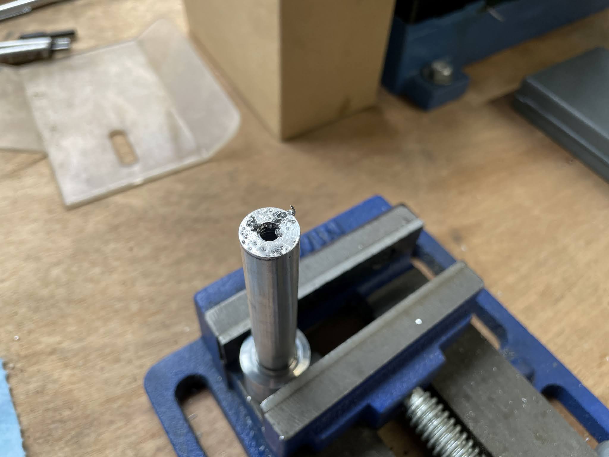
That just leaves the 7075 spindle shafts, which also needed to be shortened by 1.000". Cutting off the extra length and extending the outboard mounting hole was a quick task for the mini-lathe. Then, it just needed to be re-tapped.
 |
| Shortening the 7075 spindle shafts... |
 |
| ...and re-tapping. |
Finally, I put everything back together, substituting much lighter 4"x1/2" hex standoffs to span the gap at the top of each wheel module. The total process took only about two hours per wheel, including disassembly and reassembly. So something I have put off for two years was really only one day of work...typical. Anyway, the final result is a kart that's now 2" narrower and about 1lb lighter.
 |
| The pile at the front is roughly the weight saved. (5"x5/8" standoffs were replaced by 4"x1/2", but an equivalent amount of weight was taken out of each hub.) |
I have a few more tasks I want to do on this kart. It still needs to be fully weather-proofed. I have a plan for enclosing the motor drives, but need to figure out something for the steering wheel PCB. I may redesign that board from scratch since I don't think I'll ever get to using the battery balancing circuit on it. It can be much smaller and simpler without that. Lastly, there's always motor drive stuff to fiddle with to squeeze out more torque and/or speed.
For now, though, I'm glad it's a little lighter and a lot narrower. It'll make deploy that much easier, which ultimately means more actual testing and use.
No comments:
Post a Comment