Showing posts with label pneu scooter. Show all posts

Thursday, April 19, 2012

Sensorless Start-Up / Speed Control

It's spring demo season again. I'll be at the Cambridge Mini Maker Faire on Friday, along with the MITERS crew, with an assortment of projects. Come check it out. Follow-up post to come.

For now, time for a massive multi-controller update. The Sensorless, Sine-Commutated Field-Oriented Current Control (SSCFOCC) algorithm I've been working on has been sufficient abstracted now that I can develop for it on two different motor controllers (3ph v3.1 and FFv1.0) at the same time. (3ph v4.0 is coming soon and DirectDrive v1.0 still exists, I promise...)

Before I start developing new hardware and potentially writing a entirely different sensorless control algorithm, though, there were some loose ends I wanted to clean up in the current algorithm. Once these points are addressed, I will go back and write up a summary of my first-generation sensorless code since by now it's too complex for individual blog posts.

But First...


More Position Filtering

Loose End #1 was a problem with the rotor position estimating filter used to clean up the rotor angle at high speeds. I added this at the end of the last sensorless post and even though it immediately improved the high-speed performance of FFv1.0 on the hexrotor motors, there was a weird side-effect on the flux vs. angle graph. The flux estimate would begin to lead the rotor angle estimate at high speeds, which should not happen since the rotor angle estimate is derived from the flux estimate. The flux vs. angle curve should be constant. What the?

After staring at the code for a little while, I identified this a rather complex software error on my part tracing all the way back to a subtlety of BWD's sensored FOC code... I'll spare you the details, but I fixed it and now the flux estimate is much nicer:

Pneu Scooter w/ 3ph v3.1. Compare to unfiltered flux estimate.
Much of the "noise" from the 2d plot is shown to be offset at low speed (<200rpm).
Hexrotor motor with FFv1.0. Compare to the unfiltered flux estimate.
And in nauseating pseudo-3d.
The low-speed offset is a known issue having to do with the fact that the integrator at the heart of the flux estimate is implemented as a low-pass filter. There is also a phase offset in the flux estimate resulting from this practical non-ideality:


Since this is a known offset, it could potentially be subtracted off. Or the low-pass filter could be designed such that at the start-up routine exit speed, the offset is less than 15º or so. For the data above, that would be about 150rpm. Speaking of start-up routines...

Start-Up

Loose End #2 was the lack of any start-up routine for either controller. I've been putting it off for a number of reasons. For one, Pneu Scooter really doesn't need a start-up routine. The sensorless algorithm has no trouble picking up the rotor speed at as low as 50rpm and that's well within single-kick speeds:

One kick gets to 75rpm, at which point the flux estimator has locked in.
Also, Pneu Scooter really doesn't have enough torque to justify a no-kick start-up routine. Even at peak current (40A), the acceleration is something like 150rpm/s. The sensorless start-up will achieve far less than peak torque, though, since it won't have the benefit of optimum current vector placement. So it could mean a couple seconds of balancing on a barely-moving scooter while the speed ramps up. It's just much more natural to kick start.

FFv1.0 and the hexrotor motors, on the other hand, almost definitely need a start-up routine. Even though in this video, a very large (14x4.7SF) prop starts cleanly and quickly with no start-up routine at all. The command PWM goes high enough that the motor is forced to do something, and by luck it gets kicked in the correct direction at sufficient speed for the flux estimator to lock in. But this is unreliable (works maybe 50% of the time) and inelegant, so it should really have a slow-ramping startup routine as well.

Maybe the real reason I haven't implemented a start-up routine yet is because it's easy. At least, the most obvious way of doing it is easy. Lacking position information, there isn't much choice in how to drive a brushless motor: it becomes a coarse stepper. Except with sinusoidal commutation it can be like a microstepping coarse stepper, which is still pretty smooth. The point is, the only way to drive it with no knowledge of the rotor position is to put current in somewhere and wait long enough to know that the rotor has most likely reached the position you told it to go to. With that in mind, I wrote a simple start-up routine with four states:
  1. IDLE: Wait at zero speed until the user commands a positive torque or speed.

  2. PARK: Place current vector at a fixed angle and wait for some time for the rotor to reach a stable position.

  3. RAMP: Rotate the current vector with a constant angular acceleration that is sure to be achievable by the rotor given the amount of current commanded and the estimated load inertia.

  4. RUN: After a certain speed, switch to sensorless field-oriented control using the rotor angle predicted by the flux observer.
The ramp state here differs a little from BLDC-style sensorless start-up routines that use six-step voltage-mode commutation. Since this ramp state is still current controlled, the possibility for variable user-commanded acceleration during "open-loop" start-up is present. The angular acceleration of the ramp is linked to the amount of current commanded. If you go light on the throttle, the ramp takes longer.

Since the load inertia can't be exactly known, the start-up ramp acceleration has to be conservatively chosen. The start-up torque will therefore be significantly less than the run torque, and the efficiency will be very low. This is a common trait of sensorless start-up algorithms and the best way to minimize the effect is probably to get out of start-up as soon as possible. Transitioning to closed-loop sensorless control at 5-10% of the maximum speed seems to be achievable.

Anyway, enough hypothesizing. Here is my first shot at a sensorless start-up for Pneu Scooter, the harder of the two challenges:


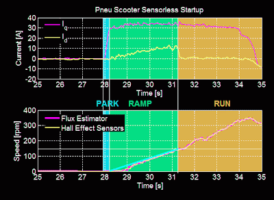
The ramp goes from 0 to 150rpm in about 3 seconds with 30A commanded current. This is about 50% of the acceleration that would be expected from closed-loop control, so it feels sluggish for the first three seconds. But, it is smooth and transitions cleanly to run-state closed-loop control at 150rpm. Making the ramp faster results in pole slipping, so this is about as good as it will get.

One option for improving the start-up is to get out of the ramp state earlier. The flux estimator is able to pick up the rotor movement at as low as about 25-50rpm, so waiting around until 150rpm sounds silly. But, the low-pass filter-induced phase lead is still very high at those speeds, so the transition doesn't work reliably. It's clear that the low-pass filter time constant and the ramp exit speed are coupled in this way. Something to think about for future optimization.

Another option is to use more current. This doesn't help the efficiency, but it will create a faster ramp. 60A for a short period of time shouldn't hurt the motor or controller, but I'll wait for 3ph 4.0 to test that.

Start-up for the hexrotor motors is a much simpler problem. For one, they have essentially no load at start-up when the prop is moving too slowly to create significant thrust or drag. The performance of the controller is also not at all dependent on low-speed torque characteristics since the minimum RPM seen in flight will be well above the run-state threshold. Here's a very light ramp (<5A) for the 14x4.7SF prop:


The threshold for transitioning from ramp state to run state is 600rpm, and once it transitions to run state the torque increases dramatically. The ramp can afford to be much faster without slipping poles, but for the purpose of reaching a safe idle speed for the prop, it almost doesn't matter. Note that the speed goes directly to idle speed, 1,000rpm, and sits there. That brings me to...

Speed Control

Loose End #3 is speed control for FFv1.0. Pneu Scooter, as a vehicle, is happy with current (torque) control. But for the hexrotor, the master controller may want to command an exact speed for each rotor. Speed is directly related to static thrust (though not linearly). Steady-state current is also related to static thrust (close to linearly). But with inertial transients to deal with, the performance of a speed-based controller might be better.

Actually, the simple way to do "speed" control is to directly vary the PWM duty cycle, bypassing the current control entirely. This controls speed because motor speed is approximately proportional to applied voltage, which is controlled by the PWM duty cycle. As it turns out, it's definitely possible with the modified Synchronous Current Regulator (mSCR) to use this control mode, bypassing the q-axis current controller but leaving the d-axis (phase) controller working. This gives the benefits of FOC (dynamically adjusted motor timing) but the simplicity of direct PWM control. In fact, this was what I used for the first few tests of FFv1.0. Here's some data showing it executing step "speed" commands:


At each step, the q-axis and d-axis current spike due to the inertia of the motor and prop. But, the back EMF brings the q-axis current back to a steady-state value as the prop speeds up or slows down, and the mSCR adds or subtracts from the phase to bring the d-axis current back to zero.

The benefits of direct PWM magnitude control are simplicity and robustness. With current limiting to prevent the spikes from damaging components, I think this could be a pretty good way to run a multirotor controller. It's how most ESCs operate, so it would feel normal. But, it has several downsides:

  1. It can't achieve minimum rise time. The step in voltage magnitude will give only as much current as the motor resistance will allow. A smarter controller could slew the motor faster using a voltage that is higher than the steady-state value at the target speed.

  2. It can't accommodate minor difference in motors/ESCs/props. If one motor is slightly weaker than the others, it will spin slower under PWM magnitude control. The master attitude controller's integral term can correct for this, but why rely on this?

  3. Motor speed is only roughly proportional to applied voltage. The actual speed depends on the back EMF, which is V-IR. At higher loads, the speed per applied volt is lower. Does this matter? Maybe not, since none of this is linearly proportional to thrust anyway.
A classical approach to true speed control would be to wrap an outer PID control loop around everything:


The speed control loop, a generic PID with saturation, feeds the q-axis current reference a value between the maximum braking current and the maximum accelerating current, depending on the speed error. The d-axis controller is still simply trying to maximized torque per amp by adjusting motor phase. (The more I think about it, the more the mSCR strategy makes sense in this regard.)

This video shows the start-up and PID-based speed control for FFv1.0 with the 14x4.7SF props:


The nice thing about PID control is that it's easy to understand and easy to tune. Unfortunately, the load in this case is very nonlinear. As the speed increases, the damping due to propeller drag goes up. So, the step response changes depending on the speed:

Real data from the 14x4.7SF prop.
From 1,000-2,000rpm, the chosen gains exhibit a lot of overshoot. From 4,000-5,000rpm, they're overdamped. With this data as a starting point, I made a quick simulation including the nonlinear prop load. Another nice thing about PID is that it's very easy to work with in a Simulink:

This is what grad students do all day.
After some shady parameter estimation, I could almost predict the step response shapes:


The real-life response is actually a bit faster than the simulated response, for some reason. Not going to complain about that. But, they're both pretty slow overall. The motors never reach peak current during speed steps. The slew rate can and should be much faster for the best possible speed command tracking. By tweaking the gains in Simulink, I can now get a feel for which way they should be pushed in real life to speed up the response and kill off some overshoot.

I also think there's a better way. This post is already quite long so I'll have to save that for next time, but there is a hint of it in the Simulink diagram...

For now, I leave you with a Kramnikopter that I bought for basically nothing and will be doing absolutely zero custom development for:

Yay, not-complicated flying things.

Friday, December 23, 2011

More Sensorless

I'm still tweaking the sensorless routine for Pneu Scooter. The software framework for sensorless sinusoidal commutation and field-oriented current control is set, and now I am playing with the different parameters to see if they have the effects I think they should.

First, I hypothesized in the last post that the positive relationship between current and flux estimator offset (with respect to the Hall effect sensors), seen here, was due to underestimated inductance. At high current, the rotor electrical angle predicted by the flux estimator would lead the angle interpolated from the Hall effect sensors, which I trust to be more accurate. Based on this figure, if the inductance parameter is too low, the [-IL] vector will be too short and the estimated flux vector will lead the actual flux vector at high current. 

To test this, I changed only the L parameter in the sensorless code definitions, from 200μH to 300μH, leaving all other settings the same. After another 15-minute outdoor test drive, I plotted the flux estimator offset as a function of current once again. Here it is with the old data for comparison:


The effect is exactly what I thought it would be, flattening out the slope so that the offset is constant (near zero) though the entire range of load currents. I may have even gone a bit too far, creating a very slightly negative slope. But now I know that the inductance parameter has as predictable effect. The lead induced by using an inductance parameter that was 33% too low was about 20º electrical at maximum current. The error sensitivity is easy to predict using the vectors in this figure, but I will spare you the analysis in this post.

A closed-loop flux observer, which some day in the future I will certainly try out, would seek to minimize the effect of an over- or under-estimated inductance parameter. The ultimate goal would be plug-and-play sensorless that adapts to any motor on the fly. But for now, I can live with nicely-behaved dependencies like this. Though, without the parallel-processed Hall effect sensor data, I would be lost as to how to characterize any of it.

I also tried out the sensorless controller on a different motor:


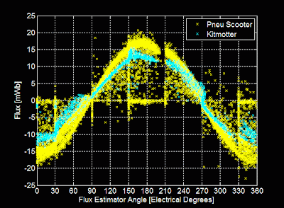
The thing clamped to the table is Kitmotter, a demonstration motor with very similar characteristics to Pneu Scooter's wheel motor. They have virtually the same measured inductance. Kitmotter has a higher resistance, which I modified in the sensorless code definitions for this test. It also has a lower torque constant, which is not an explicit parameter in this sensorless algorithm. What it does mean, though, is that the flux magnitude should be lower:


And in fact it is, by a small amount. It's also interesting to see that the general form of the flux estimates is very similar for both motors. In particular, the gap between about 200º and 210º shows up in both cases. This eliminates the possibility that the gap is caused by some asymmetry in one motor's winding. It could be current sensor asymmetry, though.

Kitmotter also accidentally allowed me to test the fast overcurrent shutdown. The dangling mess of alligator clips seen above was not the best idea, and when two of the phase outputs shorted to each other, causing a large spark, the controller shut down properly and gave an overcurrent fault. No dead FET.

The next parameter I want to tweak is the low-pass filter time constant, which affects the low speed performance of the sensorless control. I mentioned that the low-pass filter causes the flux estimator to lead the true angle at low speeds, and showed the offset as a function of speed. Here it is again, but in pseudo-3D:

Is this nauseating?
Below 200rpm, the flux estimator angle is greater than the Hall effect sensor angle (trusted to be the true electrical angle). This causes the data, which should lie on the x = y plane, to slope off to the left at low speeds. Making the low-pass filter time constant longer should flatten out the plane and improve the low-speed torque. A lower "valid data" speed for switching to sensorless control will make start-up ramping, when I get around to that, just a bit easier.

I'm also worried about high-speed operation, which was the problem that magically disappeared when I made several code improvements. But, I'm still working with relatively slow motors, having commutation frequencies of 200Hz or less. I'm interested to see how things change (probably for the worse) when I try to run a non-direct-drive (indirect-drive?) motor like that of tinyKart, which can hit 750Hz or more.

More testing to come...

Sunday, December 18, 2011

Sensorless Pneu Scooter: Part 2

Pneu Scooter is now Sensorless Pneu Scooter! (Which means I can ride it again.)

This is the follow-up to Part 1: Where I make my code much fancier. Most of the work of the past two weeks went into setting up a new timing structure for the control code, which is summarized by this graphic. The controller has a fast loop, which runs at 15.625kHz, and a slow loop, which runs at just under 1kHz. The slow loop handles the computationally-burdensome Field-Oriented Control (FOC) calculations, and hasn't changed since I first implemented it on B.W.D. long ago. The concept of FOC is summarized in these two posts, and is shown in this, the first of many neon graphics I color-inverted for this post:


FOC seeks to keep stator current, I, in phase with back EMF, E, which is equivalent to saying that it keeps stator flux 90º ahead of rotor flux. This produces the most torque per amp. To keep the current and back EMF in phase, the voltage, V, is phase-advanced by the controller to counteract the effect of inductance. 

All these quantities are treated as vectors (really, the magnitude and relative phase of a set of balanced three-phase sine waves). The coordinate system is aligned with the rotor's magnetic field (hence, "field-oriented") and the axis on which the rotor flux is at a maximum is called the Direct (D) Axis. The Quadrature (Q) Axis leads the D-Axis by 90º electrical in the direction of rotation.

Because the coordinate system is locked to and spinning with the rotor, the position of the rotor must be known with good resolution for any of this to work. Previously, I used Hall effect sensors and time-based interpolation to derive the position. But, as the name would imply, Sensorless Pneu Scooter needs new tricks that do not rely on Hall effect sensors. To obtain the rotor position, the fast loop estimates flux on all three phases. The flux estimator I chose to start with is a very simple one:


It's an "open-loop" flux observer that derives the rotor flux linkage from measured currents, driven voltages, and a good estimate of the motor's resistance, R, and inductance, L. The vector version of this flux estimator is shown in the image above. Note that the integral of a given vector is another vector which lags by 90º and is scaled by the angular frequency:


Which brings up another good point: Unlike back EMF, flux does not vary with speed, so the flux estimator should produce a constant magnitude at any speed. As the V and E vectors increase in magnitude, the scaling by ω keeps the integral-form from growing.

The figure above is actually somewhat misleading. For one, the flux estimator doesn't run in the rotating D/Q coordinate system, but rather in the stationary frame, on each of the three phases independently. Also, the estimated flux on each phase is a scalar quantity; it's just the magnitude of the rotor flux seen by that particular motor phase at that particular instant. To derive position from this, I take an unusual approach of watching for flux zero-crossings (with hysteresis) and feeding these transitions to the same interpolation routine that my Hall effect sensors would have gone to.

In this way, the flux estimator is always running in parallel with the Hall effect sensors and control can be given to either one at any point in time. Additionally, they can be compared to each other. So, as I've been test-driving with the sensorless position estimate in control, I've been logging data from both. Cue the rest of the neon graph sequence:


All of the the data in this post was recorded during a five-minute outdoor test drive with the sensorless position estimate running the field-oriented control. The top plot above shows effective regulation of Q-Axis current to follow the throttle command, and the D-Axis current being held close to zero. The bottom plot shows the speed estimates produced by both the Hall effect sensors and the flux estimator. (Both calculate speed by measuring the time for one full period of rotor flux.) They are nearly identical at all speeds, including below 100rpm.

Speed is not sufficient for control, though; the flux estimator needs to be able to accurately derive the rotor position. Comparing the rotor position derived by the flux estimator to that of the Hall effect sensors reveals the following:


The ideal case would be a straight line with a slope of one, indicating perfect agreement between the flux estimator and the Hall effect sensors. There is a good deal of noise in the position estimate, but the general 1:1 correlation is there. The flux estimator angle leads the Hall effect sensor angle slightly, shifting the entire line upwards by about 15º. This is not necessarily the fault of the flux estimator; it could be interpreted as the Hall effect sensors being about 15º behind neutral timing.

To get more of a feel for the source of the noise around the 1:1 line, I plotted the relative phase offset between the flux estimator's angle and the Hall effect sensor angle as a function of a few other quantities. First, speed:


There are several interesting bits of information in this plot:
  1. At any speed, the band of uncertainty in the position estimate is still about 30º. Therefore, there must be factors other than speed which cause offset in the position estimate.
  2. The bulk shift of 15º (flux estimator leading Hall effect sensors) is clear in this plot too.
  3. At low speeds, the flux estimator leads the Hall effect sensors even more. This one is easy to explain. Instead of a pure integrator, I implemented a low-pass filter on (V-IR) as part of the flux esimator:
Pure integrator.
Low-pass filter.
The low-pass filter is used to keep the integral from drifting away. It's combined with a gain of τ, the filter time constant, so that at high frequencies it looks like a pure integrator. But at low frequencies, it has less than the -90º of phase a pure integrator would give:


At the corner frequency I chose for the low-pass filter, 0.053s, the low-pass filter causes the flux estimator to lead significantly at low speeds. The blue line in the offset vs. speed plot above is the theoretical lead induced by the low-pass filter. Setting the filter time constant to be longer would push the speed at which lead becomes significant down lower. Since the data seems to clearly show this effect, I would like to run some tests where all I change is the low-pass filter time constant. Obviously a longer time constant would be better for low speed operation. Integral drift might hurt the performance overall, though.

I also plotted the offset between the flux estimator angle and the Hall effect sensor angle as a function of load (Q-Axis current):


Here, another clear trend was revealed: the flux estimator lead increases with current. My hypothesis on this one is that the inductance estimate is low. In the first graphic of this post, the -IL vector would be too short if L were underestimated. This would cause the estimated flux to be somewhere in the upper-right quadrant, leading the true flux, which is on the D-Axis. Again, since the data shows a very clear trend, I would like to run some test where I vary only the inductance parameter to see if I can flatten out this line. 

This particular dependency (position error as a function of load) is one that I think can be avoided as I pursue more advanced sensorless algorithms. A "closed-loop" flux observer would be able to more readily handle misidentified motor parameters by using feedback to adapt the motor model or negate some of the effects of the misidentified parameter. Another valid option is to have the motor parameters self-calibrate, either at power-on or dynamically as it runs.

Lastly, my favorite graph of all:


I had the data spit back the actual flux estimate on Phase A along with all the phase currents. Plotting the Phase A flux as a function of the flux estimator's angle reveals a very nice sinusoidal flux that peaks at 180º and has an amplitude of about 15-17mWb. Not coincidentally, this is close to 1/7th of the motor's per-phase back EMF constant of 0.105V/(rad/s) = 0.105Wb. (The motor has seven pole pairs.)

The three phase currents are also plotted and are bounded by nice 40A sine waves, representing maximum positive throttle. Phase A's current (yellow) leads Phase A's flux (white) by about 90º, as it should if the field-oriented control is doing its job.There's a very interesting gap in the flux estimate angle just before 210º, which is also seen as a "staircase" effect in the flux estimator angle vs. Hall effect sensor angle plot. I still haven't tracked this one down or formed a theory about it yet, but this convinces me that it's an issue inherent to the flux estimate, since this plot has nothing to do with the Hall effect sensors.

Altogether, this "simple" sensorless routine has been working very well since I modified the controller timing. I can't say I understand exactly why (or even if) the changes I made to the loop timing caused it to start working, but I'm happy that it's now producing useful data and that I have new tests to try out. 

I'm even more happy that my Pneu Scooter riding ban can be lifted since it's now capable of propelling itself in 100% sensorless mode.

Saturday, December 17, 2011

Sensorless Pneu Scooter: Part 1

After just about one month, my voluntary moratorium on Pneu Scooter riding is officially over. Yes, that means it is now Sensorless Pneu Scooter. Even though I was distracted by flying things for a short period of time, I have made steady progress on working out the software kinks to get my first attempt at a sensorless field-oriented control strategy up and running. This is a two-week update, so I think I'll have to split it into two parts. The first part here explains most of the code tweaking I did. The second part, to come shortly, is when the sensorless control finally begins to work the way it should. How the two parts are related to each other, I don't exactly know.

Part 1: Where I make my code much fancier.

In the last update, I had been able to get Pneu Scooter running for a short indoor test drive on sensorless control. While it worked at low speed and low load, it was glitchy at anything above 20A and seemed to completely fail at 800rpm. These may have been related or unrelated problems, and I never got far enough into troubleshooting it to find out. Instead, while test-driving, one of the glitches took out the power stage, killing the FET, at least two gate drivers, and leaving a small crater where my DC current sensor used to be:


In a previous FET failure, the trace leading into the DC bus had blown, so I reinforced it with some copper braid. This moved the weakest link to the current sensor, I guess. It's worth noting that there is a 40A slow fuse in the system but it seems never to actually do anything during failures. Maybe time to go back to the magnetically-tripped circuit breaker switch. In any case, this board is toast. Even after I repair the power stage, it will only work with the DC current sensor bypassed completely. Possible motivation to design 3ph v4.0.

I switched to my back-up 3ph v3.1 controller and took some time to implement a few software improvements, including fast over-current shutdown designed to (possibly) save the FETs if (when) the sensorless control commutation glitches. I also implemented a better ADC sampling strategy to try to clean up the current measurements as much as possible. The goal was to sample phase currents at a time where no power switching is happening, since the switching transients can couple noise onto the current sensor signals.

First, the three PWM timers are synchronized (no easy task) and set to center-aligned mode, producing nested and symmetric voltage ouputs. In addition to reducing ripple on the DC bus capacitors, this has the benefit of creating a guaranteed point in time where all three PWMs are off. This is where I wanted to trigger the ADC to sample phase current. The STM32F103 has all sorts of interesting timer and ADC setup nuances that I discovered. After several days of messing around with timer and ADC configuration registers, I got to this:

Scopemas Tree.
I had to overlap the three voltage outputs to get all the traces to fit on the scope. Here, they are running with duty cycles of 25%, 50%, and 75%, just to illustrate what center-timed PWM looks like. Timer 1 is the master and the other two are synchronized to it. I set up an unused Timer 1 compare output as the trigger for the ADC, and I configured the dual ADC so I can convert two measurements simultaneously. I group and order the measurements as follows:
  1. Phase A Current & Phase C Current
  2. DC Current & DC Voltage
  3. Throttle & Nothing
The phase current measurements are most important, so they go first, triggered just before the center of the "off" portion of all three PWMs. The other measurements are more heavily filtered in hardware and software, so I don't care about protecting them from the switching transients. With my ADC configuration, it takes about 1.7μs to sample the two phase current analog signals. So, I set the ADC trigger to occur about 0.85μs before dead-center and expect it to finish 0.85μs after dead-center. After that, there is about another 2μs of conversion time, when the ADC translates the sampled voltage into a digital value. Then, an interrupt is triggered which stores the result in a variable. Zooming in on the center of the PWM, the timing of the first two sample-and-converts is something like this:


This scope plot also shows the motivation for sampling the phase currents away from the transitions. The tiny bits of ringing at each switching event show up everywhere: on other voltage outputs and on the digital line being used to illustrate processor timing. So, by leaving a window where all three PWMs are off and sampling the phase currents exactly in that window, the noise is hopefully reduced. The width of this "all-off" window has to be just a bit wider than the ADC sample time of 1.7μs, so perhaps 2μs. That limits the maximum duty cycle at 15.625kHz to 2μs/64μs, about 96.8%. Since the gate drivers are bootstrapped anyway and need some off-time to work at all, this seems like a reasonable limit.

After the three sets of ADC conversions, the fast loop is triggered and runs the sensorless field-oriented control routine using the freshly-converted current measurements. I also added some fast over-current shutdown code to kill the gate drive if any of the phase currents or the DC current exceed a maximum limit, positive or negative. Hopefully the combination of cleaner current measurments and shutdown within 64μs of an overcurrent fault will have some chance of saving the FETs if there is a controller glitch.

In case the last 1,000 words weren't very clear, here's a graphic showing the controller timing in its entirety:

(Click to enlarge.)
There are still some minor tweaks I want to make to the code. One way to save a ton of time is to use the Direct Memory Access (DMA) peripheral to automatically store ADC results in memory. Theoretically, this would cut the entire ADC block down to about 10μs. I'm also still running at only 32MHz. I don't need it yet, but the processor is capable of 72MHz in case I want to add more fanciness to my fast loop.

But for now, this setup seems fine. After loading the new version of the controller, Sensorless Pneu Scooter magically started working the way it should. I didn't think I had changed anything fundamental, but the performance is much better than it was before, almost indistinguishable from the previously-sensored Pneu Scooter. I've been riding it around for a few days now with no problems.

In Part 2, I'll get to the sensorless scheme itself and the data I've collected during my few days of test driving...

Friday, December 10, 2010

Brake, Lights, Tacos, and the Rad Hardened 3ph 3.1

I've been braving the cold to get in more Pneu Scooter test driving. The first test drive was this 2.1 mile campus tour, after which I predicted a total range of 4-5 miles. But in order to actually test that, I wanted to take it off campus to one of the locations that I felt might be in striking distance: Taco Bell. (I was also hungry.)

Before I even started that trip, though, I had to put on the brakes.

No, literally.

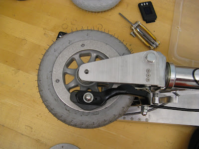
Like everything else about the front fork design, the brake layout just somehow works. I didn't plan it beyond having a pretty good idea where I would attach the calipers (which came from here). The strange vertical orientation of the pads was not part of the plan but worked out nicely anyway. The metal disks serving as makeshift brake surfaces are massive shims I got from McFaster-Carr (PN: 97063A136). (Seriously, I missed being able to just order random shit like this so much when I was in Singapore.)

Pneu Scooter does have regenerative braking. Not the type that you put on a roller coaster in order to power an entire amusement park. (Seriously people? Do you not understand regenerative braking or do you not understand roller coasters?) But it does capture an insignificant amount of kinetic energy as you slow down. I have it set to pull 10A back out of the motor when you fully release the throttle, which is enough drag that I almost never need to stop any faster. The mechanical brakes are mostly just a back-up in case the controller fails.

I should be adding brake lights, or handlebar headlights, or something related to safety, but instead I went with running board lighting:


It's just four LEDs powered by the balance leads for the batteries, which are up front anyway. The LEDs are embedded into the side of the polycarbonate skid plate, so some of the light creates a Tron-like stripe on the bottom of the deck. I think it's less obnoxious than cold cathodes.

So, off to Taco Bell!

This is what it looks like to go to Taco Bell.

Notice the phase advance effectively canceling out d-axis current the whole way. (What?) I've got to believe this adds a mile or so to the total range of the scooter, as compared to blind current magnitude control or something like that. It's ensuring that every amp that goes in is producing torque.

Here's a 60 second window of relatively high power cruising:


The peak is about 750W in and 500W out. You can see it tracking the q-axis command so well that the command and the measured value basically overlap. The total round trip summed to 3.7 miles, with an energy consumption of 90Wh, for an efficiency stat of 24 Wh/mile. Of the nominal 4.4Ah capacity, 2.7Ah were used. From this I conclude that the full range is probably about 5 miles, on the high end of what I estimated last time. The stator was borderline frighteningly hot after the trip, so I don't think I can push the current much more than what it was here (40A peak).

You might also notice the random downward spikes in the current data. These are the microcontroller program counter getting randomly thrown into empty program memory due to something horrible that I don't even want to think about. I've got the watchdog timer set to reset the processor if the control loop stops running, but each reset is accompanied by a momentary loss of torque that is somewhat disquieting, especially since it tends to happen at peak current. I added a bunch of countermeasures to the 3ph HD to try to eliminate these resets, but none completely solved the problem.

Cue the Rad Hardened 3ph 3.1.


Ok, it's not actually radiation hardened, but it is protected in many ways from the sorts of noisy electromagnetic nastiness that accompany a 40A hard-switching power system. I don't know or care exactly which of the additional protections contributes most; this is more of a shotgun approach to noise reduction employing everything short of optocoupled gate drive (the fallback plan). Here's the new, cleanly net-labeled schematic of v3.1.

(Click to enlarge.)

The new logic power supply is an isolated 2W DC/DC converter made by TI (DCR021205). After finding that some extra resistance in the connection between logic and power ground greatly improved the performance of the previous controller, I decided an isolated supply might be a good idea. Somehow, TI crammed a transformer-based 2W DC/DC converter into this:

(For scale, that is a 1206 capacitor.)

This is great, except, I can't really float the grounds, for two reasons: One, my battery voltage measurement is not isolated; it's just a resistive divider and low-pass filter feeding the ADC. And two, the gate drive can only tolerate a +/-5V offset between logic and power ground. So, I still need to tie the grounds together, but ideally no current should be flowing directly between the two. Dilemma? Yes. That's why I have the value=IDK resistor bypassing the isolated supply. I honestly don't know how to choose it. I randomly guessed 1k, and it seems to work, but there is a 1.3V drop across it right now. Why? I don't know. If it doesn't impact functionality, I don't really care.

Stage two of the ruggedization plan involved, to steal a phrase from Amy, "capping the shit out of everything." The capacitor in the picture above is just one of many 100uF, 1206-package low-ESR ceramic capacitors now bypassing the 5V and 3.3V rails across the board. Additionally, I moved all the low-pass filter capacitors right next to their respective ADC pins to eliminate the current sensor noise I discovered in Singapore:


Also pictured above: more large bypass caps and a 5V transient voltage suppressing Zener diode. This is designed to absorb voltage spikes by breaking down at a known voltage, protecting other components on the 3.3V line. I neglected to put one on the 5V line in the board design, so I made a flying Zener:


To make all this room on the board, I had to move the switching 15V power supply (now 13.5V to accommodate the 12V input of the DCR021205) down to the bottom side, which creates a bit of a problem because the electrolytic capacitors are taller than the IXYS MOSFET module by about 1mm. I'll have to fill this additional gap with a thermal transfer pad on the bottom of the FET (which is probably a good idea anyway). But now, the top side is all logic, and the bottom side is all serious business:

Pictured: All that parts that violate FCC standards.

I used to worry about finding more IXYS three-phase modules, because they have a very unique footprint and so my design is married to them. However, Mouser seems to stock them now. I would like to try some of the other flavors (75V/120A) if they ever show up. For now, I have horded enough to last for quite a while:

 This is my favorite box ever.

I made a few other minor changes that may or may not have contributed to the overall noise reduction:
  • Individual local bypass capacitors for the three current sensors. (Previously, all shared a single 5V bypass.)
  • A ferrite chip in series with the 5V trace that feeds the STM32 board (L2 in the schematic). This should help filter any current spikes attempting to go toward the microcontroller. In retrospect, a common-mode choke probably makes more sense.
  • Local low-ESR ceramic bypass for the 5V pin going to the Hall effect sensors. Since the problems seem to only occur when the motor is moving, I thought there was a slim possibility that the sensors might be contributing. Even if not, it's just extra bypass for the 5V line.
  • 1k series resistors (R50-R53) on all the gate drive digital outputs (three PWMs and a shutdown signal). I'm not sure why, but I thought it might help if the noise is coupling in from the gate drivers themselves.
The down side of making so many changes at once is that I have no idea which ones specifically make a difference. The up side is that I give myself the highest probability of solving the problem. And, I'm happy to report, the problem is solved. Here is a clean full-throttle (40A) launch:


Command following is spot-on and he torque output is very smooth. I haven't test-driven it enough to say that the random resets are gone forever, but I have yet to observe one on the new controller.

Next step: Combining this with the MIDI engine to make the worlds first? vehicular MIDI instrument.