

In the interest of fair reporting, I will say the that feature set of the TMS320F28069 microcontroller does give it a few advantages over the STM32F103C4 that I currently use. It's a 32-bit processor (not ARM based) and can run at up to 80MHz. But, it has a built-in FPU and control-law accelerator, something not found until the F4 line of the STM32s. It also has more PWMs (16) and ADCs (16) than the smaller STM32F1s. As far as the available IDEs, I've used both IAR EW and Code Composer Studio before and I find them to be equally annoying. And I hate JTAG/emulated debugging anyway.
I don't see myself switching away from the STM32, but I've had good experiences with the TI MSP430 line and I wouldn't hesitate to recommend those or the more powerful C2000's for people looking to escape from Arduinoland.
Since I'm always talking about how convenient it is to have a compact electric scooter that folds so you can take it on public transportation, I decided to try it out on my way out to Waltham. The bus from near me stops just on the other side of Prospect Hill Park from the TI offices:
 |
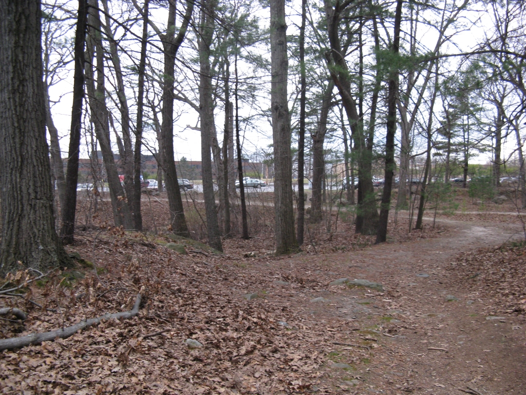
| No problem. This should be a nice traffic-free scooter ride through the pa- |
 |
| Oh. |
 |
| So I guess I'll be hiking. |
 |
| Also, some of the paths are just dirt trails. The good news is that that's the TI parking lot right there. |
Well at least I could have a fast trip down the hill on the way home - Oh no wait, it tore my brakes apart on the first two days. By the third day, with repaired brakes, I had pretty well optimized energy usage so that I could minimize hiking up the hill and coast the entire way down. Still better than driving in Boston rush-hour traffic.
Anyway, although all three days of workshop were great, I was especially interested in Dave (Wisconsin) Wilson's Motor Control Seminar. Most of the slides are available on his blog if you are interested. I learned a bit more about TI's InstaSPIN BLDC control scheme, and am beginning to sort out the various types of sensorless control methods.


One thing I picked up which I have to think more about is that what I have previously referred to as an open-loop flux estimator is in fact not as far different from a closed-loop observer as I had thought. The difference is more subtle and possibly less fundamental than it seems. For example, here is a closed-loop single-phase back EMF/current observer with a PI compensator:

With just one page of math, I can unwrap the feedback loop and rewrite it in the form of my "open loop" flux estimator, plus an additional low-pass filter. The closed-loop form still has the advantage of keeping an internal state for current estimate, which is probably way cleaner than the measured current. But they're not fundamentally different as I had once thought. Go figure...
Maybe the important distinction then isn't between open-loop and closed-loop formulation for the observer. Maybe the fundamental difference is between observers that work only on electrical quantities and ones that include a mechanical state (speed, position). The addition of a mechanical state would almost certainly improve the performance of either observer, since it would anticipate the trajectory of I and E as the motor rotates. No wonder this is the type of observer described in the Book of Mevey, which has been right about everything else so far.
Back to reality.
My immediate task is to get this thing spinning:

After realizing that I wouldn't be able to hear anyone coming over the noise of the propeller, I added this:
 |
In the previous post, I had gotten FFv1.0 up and running using Pneu Scooter as a test motor. The TI DRV8301 gate driver/everything chip performs well. But, the first time I attempted to run the motors on the hexrotor, I ran up against some not entirely unexpected issues with high speed control. At full speed, the electrical frequency of these motors can be 1,000Hz or higher. Every part of the control loop from the currrent sensors to the digital filters has to keep up with this, and in fact exceed it by a large margin to minimize phase lag. This is a tall order with a 15.625kHz PWM-limited control loop.
What I found on the first attempt is that at high speeds, the flux estimate becomes noisy and its zero-crossings, which are used to mimic Hall effect sensor transitions in my sensorless method, become blurry and unreliable. As a result, the position estimate would become noisy, which would lead to incorrect voltage vector placement. This leads to even more noisy current which leads to an even more noisy flux estimate, and so on. The physical result would be a motor that sounded very unhappy and current measurements that are all over the place starting at just under 5,000rpm. Under load, it could lose sync and crash entirely, surviving only because it was running on a current-limited power supply.
As an attempt to remedy the problem, I'm trying an idea I first thought of a long time ago for use with Hall effect sensor-based field-oriented control. The algorithm already uses a time-based interpolator to work between one flux zero crossing (or Hall effect transition) and the next. Instead of trusting the new zero crossing's position estimate 100% of the time, it's possible to use an IIR-style filter to merge the interpolator with the new position. Maybe this will help:
At high speed, when the blue vector is popping up at the wrong time due to noise, this filter will help stabilize the rotor angle estimate. And what a difference it made, without any tuning whatsoever. Here's some video of spinning up the larger prop, a 14x4.7SF:

Things are mostly in the right place and the flux estimate has the correct magnitude. (The flux is related to the motor constant or the rpm/V constant.) Something fishy is going on with the phase of the flux estimate. Its peak should stay right on 180º, since that's being used to define the d-axis. But instead it starts to shift forward at high speeds. As it turns out, I messed up the filter code a bit, so I'll have to go back and fix this one later.
For now, I also did some benchmarking against a Turnigy Sentilon 100A HV, a very good brushless motor controller. I measured (using a clamp multimeter) the AC RMS phase current and the DC bus current at different speeds running with the Sentilon 100A HV and with FFv1.0:

What I found on the first attempt is that at high speeds, the flux estimate becomes noisy and its zero-crossings, which are used to mimic Hall effect sensor transitions in my sensorless method, become blurry and unreliable. As a result, the position estimate would become noisy, which would lead to incorrect voltage vector placement. This leads to even more noisy current which leads to an even more noisy flux estimate, and so on. The physical result would be a motor that sounded very unhappy and current measurements that are all over the place starting at just under 5,000rpm. Under load, it could lose sync and crash entirely, surviving only because it was running on a current-limited power supply.
As an attempt to remedy the problem, I'm trying an idea I first thought of a long time ago for use with Hall effect sensor-based field-oriented control. The algorithm already uses a time-based interpolator to work between one flux zero crossing (or Hall effect transition) and the next. Instead of trusting the new zero crossing's position estimate 100% of the time, it's possible to use an IIR-style filter to merge the interpolator with the new position. Maybe this will help:
 |
| Maybe. |
When the new flux zero crossing or Hall effect sensor transition comes in, it generate an angle (blue) which previously would be taken as the true angle. Now, that blue angle is averaged with the current estimate based on time interpolation (brown) to create the new estimate (purple). The relative degree of weighting for the average is set by a parameter, A, just like and IIR filter.
At high speed, when the blue vector is popping up at the wrong time due to noise, this filter will help stabilize the rotor angle estimate. And what a difference it made, without any tuning whatsoever. Here's some video of spinning up the larger prop, a 14x4.7SF:
One interesting thing is that I haven't even written a startup routine yet, but most of the times it starts just fine. I guess I'm used to vehicle controllers where if you don't write a startup routine they just sit there and buzz angrily. Also interesting is that once it does start, it can run at as low as 370rpm, which is about 7.5% of the top speed. So that would be my target speed for exiting the startup routine and entering run mode.
I can tell from the data that the angle filter helped a lot - the current is much cleaner. Here's a plot of the flux and phase currents with respect to the estimated angle:

For now, I also did some benchmarking against a Turnigy Sentilon 100A HV, a very good brushless motor controller. I measured (using a clamp multimeter) the AC RMS phase current and the DC bus current at different speeds running with the Sentilon 100A HV and with FFv1.0:

The not-very-interesting result is that they pretty much overlap so far. So I am at least not doing worse then good-but-dumb brushless DC controllers. It's definitely possible that any advantage of FOC will be lost in these motors because they are so efficient in BLDC mode already. Typically, high-speed low-inductance motors can operate very well with square wave drive.
But there are other advantages that I'm still counting on. One which I was reminded of accidentally is that this controller can do four-quadrant drive. It can, in fact, brake so hard that it can unscrew the prop adapter and send a propeller flying across the room. Having braking should improve the response time of the motors to negative speed steps, which can help the control be snappier.
I've only just barely scratched the surface of the number of parameters that can be tuned. My next task will be to explore the effects of changes to the various motor parameter estimates, the filters, and the limits. Then, to see how it responds to more dynamic inputs. Then collapse everything into a simple enough interface that it could be used by other people. But so far, it's been a relatively problem-free controller build for once...
In your color-inverted "maybe" picture of a rotating vector depicting estimated theta, I think you have a maths error in your exponential (IIR) filter: there should be a hat over \theta_n in the last term... or do you really mean to depict an actual (measured) \theta?
ReplyDeleteI agree the notation is bad, since neither is the actual position. They should both get hats but have different subscripts. I will change this in the write-up I'm working on.
DeleteIt's a weird filter. \theta_n (non-hat) is supposed
to represent the absolute angle associated with the flux zero-crossing that triggers the position update. There are only six theta_n's possible, offset by 60º from each other. \theta_n^hat is the filtered position estimate, which is a linear combination of the interpolated position estimate since the last update and the absolute angle associated with the present update.