Showing posts with label motor control. Show all posts

Sunday, August 19, 2012

FFv1.2s: First Test

I got the boards for FFv1.2s, a slightly smaller version of my latest line of motor controllers:


The boards are from OSH Park (formerly DorkbotPDX PCB Order, you might be able to tell by the color scheme). It's a terrific deal for small boards: $5/in^2 for three boards. For example, this board was 3in^2, so I got six for $30. The total time from order to delivery was a bit under three weeks.

These boards have exactly the same logic section as v1.1, but an entirely redesigned, smaller power section. Instead of massive D2Pak-7 FETs, it uses Super SO-8s. These are extremely popular in RC ESCs because of their low cost, relatively high power density, and thin package (more compact and easier to heat sink). I'll be trying two different FETs: the Infineon BSC016N04LS G (40V, 1.6mΩ) and BSC028N06LS3 G (60V, 2.8mΩ).

One difficulty with using Super SO-8 FETs is that, although it's possible to solder them from the sides, good thermal performance will probably only be possible if the drain pad under the chip is reflowed. The DRV8301 magic chip needs its ground pad reflowed anyway, so this doesn't add any extra steps for me.

It's just one trip to the bagel toaster.
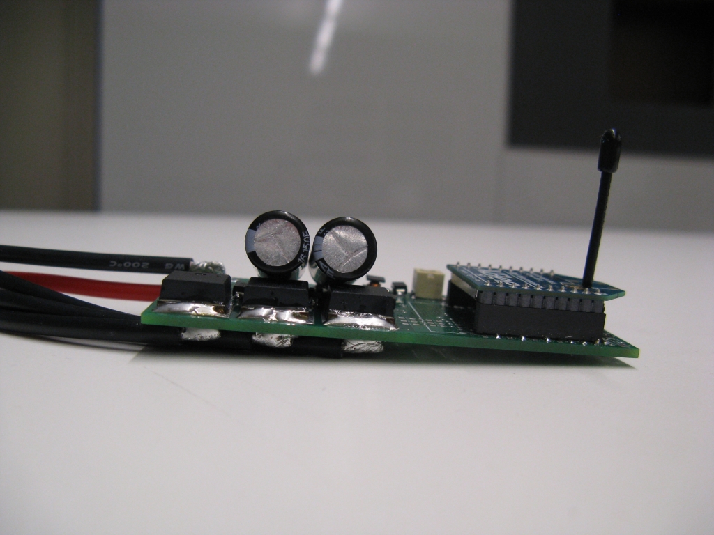
Even though v1.2s is only reduced to 2/3 of the area footprint of v1.1, there's also a significant reduction in height thanks to the low-profile FETs:


The left-most board is a v1.1 without any wires or external capacitors. The middle board is v1.2s with XBee headers fitted. The right-most board is v1.2s with no XBee headers. In the smallest configuration, it's 7mm in thickness. The tallest components are now the three pushbuttons, and even those are lower profile versions of the ones in v1.1.

Here's what it looks like wired up:


The total weight with 16AWG wire and connectors is 35g, compared to 66g for FFv1.1 with 14AWG wire. Most of the weight is in the wire and connectors. The FETs are nowhere near as beefy as the D2Pak-7s, but I think the 40V/1.6mΩ version might still be able to handle 20A continuous and 40A peak current. (Compared to ~40A continuous and 75A peak for v1.1.)

The first assembled board survived power-up without exploding, so therefore it was flightworthy.


Poor Talon quad - it really has become a test bed for just about every piece of hardware. It has so much stuff attached to it now in such a disorganized and heavy way. I put a single FFv1.2s on, loaded with identical firmware as the other three v1.1's. Since they're running closed-loop RPM control now, the slight mismatch shouldn't matter much. Here it is ready for its first test flight with the Chair of Safety still in place:


After a few successful indoor test flights, I also took it outside a few times with the data collection running. The data is from the v1.2s, which was fitted with the XBee. The other three v1.1's are running blind. Here are a couple data segments showing climbs and fast maneuvers:


RPM tracking looks good and the average current is around 5A, peak 10A. The FETs are room temperature and I suspect I won't be able to even get them warm until I try it out on the CineStar...

One more motor controller done. Time to start a new one. Here's the teaser:

Monday, August 13, 2012

FFv1.1 Air: Closed-Loop RPM Testing

With the ground firmware working well on a few test vehicles, I've moved back to the air firmware for the FFv1.1 motor controllers. (My motor controller page has finally been updated!) The challenge for the past week was to get the air firmware working in closed-loop RPM mode on the Talon quad, which has nice new motors and a new flight controller for testing.

Closed-loop RPM means that the input signal, a servo-style PWM pulse, commands a specific motor speed. (For example, 1200-1800μs could be mapped to 0-5000rpm.) In RC helicopter terminology, this is called "governor mode" and would be used to hold the rotor speed constant as the blade pitch is varied. It's not typically used on multirotors, since they have fixed-pitch propellers. But there are some performance advantages if it works well. It's also an interesting control system challenge, so I had to try it.

I had previously demonstrated closed-loop speed control with the large hexrotor motors, but the performance was very sluggish and at the time, I decided to use normal voltage (really duty cycle) control for the first test flight. It's the method that most commercial BLDC speed controllers use, and it's reasonably fast, limited only by the ESC's internal filtering. It's also a good approximation to RPM control since applied voltage is roughly proportional to motor speed in steady-state. (IR drop causes some non-linearity.)

The downsides of direct duty cycle control are that it offers no chance to limit motor current and it can't compensate for IR drop or slight differences in motors. Most of the multirotors I've used have cheap motors, and there's always one that's just a little worse than the others... Closed-loop RPM control can solve this problem by ensuring that the same command causes all the motors to spin at the same speed. 

Since I already have a current control loop from the ground firmware, adding an outer RPM control loop seemed like it would be easy. This was the loop structure I used in my first closed-loop RPM post:


Motor speed is measured by the flux observer and compared to the desired motor speed to create an RPM error. The error is sent through a PID controller and the output is the demanded current. While there's nothing wrong with this scheme, it happens to be fairly slow. There must be an RPM error in order for the PID controller to have an effect, so it's always chasing the target. To achieve faster performance, I added a feedforward term:


The feedforward term goes from RPM command directly to the current command, bypassing the PID (or in this case, PI only) controller. In steady state, motor current is proportional to the square of motor speed, due to the aerodynamic drag on the propeller. The target current is therefore set to the expected steady state current for a given RPM command, plus a P.I. term to handle transient (accelerating) current and any offset from the expected value. The constant of proportionality for the feedforward path is determined experimentally.

The speed-squared relationship of aerodynamic drag has other consequences for the closed-loop controller: 1) The damping ratio of the plant increases with speed. and 2) The damping ratio is different for increasing and decreasing speed steps. To deal with these effects, I made the gains for the outer PI loop speed-dependent and asymmetric. I don't like speed-dependent gains, but in this case it seems unavoidable for achieving good performance over a large speed range. Higher speeds get higher gains. Increasing speed gets a higher gain than decreasing speed.

The new feedforward structure, combined with speed-dependent gains for the RPM controller, improved the performance a lot. As a baseline, I implemented this scheme on the new Talon motors and tuned the PI gains to get the RPM step response as fast as possible.

::clamps quadrotor to nearest heavy object::
As expected, increasing the gains eventually led to oscillations. The test was a step input change from 2000rpm to 4000rpm. I stopped at a point where the overshoot was about 10% which was with a 0-100% rise time of 200ms. This is Plot #1 below:


To confirm this baseline, I put all the gains and plant specifications into a simulation of the controller/motor/prop system. What I found was that the real-life system was oscillating a lot more than the simulation, with the same gains. That meant there was an unaccounted-for bandwidth limit in the real controller. I spent a day tracking it down. I had already accounted for both the current and the RPM measurement filters, so it had to be something else.

The bandwidth-limiting element turned out to be the high-speed position filter I added a while ago. Above a certain speed, it merges the interpolated electrical angle with the angle indicated by a flux observer zero-crossing. At constant speed, the error between these two angles should be zero mean and the filter doesn't cause any lag. But during acceleration, the interpolated angle will lag the true angle by some amount. This lag was causing oscillation in the D-Axis current controller, which in turn was limiting the overall closed-loop bandwidth.

The solution was simple: I turned the high-speed position filter off. It seems not to be necessary now, possibly because I fixed the problem of flux offset at high speeds. Whatever the reason, the oscillation went away and the real step response looked a lot closer to what the simulation suggested it should (Plot #2). From that point, I made a few small changes to push to faster rise time:
  • Changed the RPM estimator from updating once every mechanical cycle (7 electrical cycles) to once every 3 electrical cycles. This decreases the effective low-pass filter time constant in the RPM feedback path. The tradeoff is RPM resolution at high speeds, but 3 cycles seems like a reasonable compromise. Result of this change is Plot #3. The small overshoot in Plot #2 is eliminated.

  • Doubled the gains. The result was a slight increase in rise time, but the overshoot also returned (Plot #4).  It was clear that increasing the gains more would bring back oscillations.

To improve the rise time (and the closed-loop bandwidth) further, I could speed up the inner current loop by increasing its gains or decreasing the time constant of its low-pass filtering. But the current measurements are noisy and having the filtering in place helps keep sensor noise from being amplified. (It's the classical controls trade-off between closed-loop bandwidth and noise rejection.)

I chose a different option, which was to add another feedforward path. This one goes directly from RPM command to voltage (duty cycle) output:


In some sense, this feedforward path is exactly the direct duty cycle control from before. A step increase in RPM immediately increases the duty cycle to the value that would be expected to produce that RPM in steady state. The output doesn't have to wait for the RPM or current error to build up, so the gains of the feedback controllers can be kept lower.

There is a downside, which is that the feedforward path bypasses the current limit. In the case of a large step increase in RPM command with a low-resistance motor, a short burst of current over the limit could occur before the PI controller has a chance to compensate for it. Depending on the system, a slew-rate limit on the feedforward path could be used to prevent this.

Plot #5 shows the effect of the RPM-to-voltage feedforward path. The 0-100% rise time is cut to under 100ms with acceptable overshoot and very little oscillation. The Q-Axis current instantly rises, rather than building up, giving a short burst of torque to speed up the motor. In this case, the current pulse seems within reason for what the MOSFETs can handle (although what's plotted is filtered current - the instantaneous value on the time scale of one PWM cycle is higher).

Satisfied with the step response, I loaded the new closed-loop control mode onto four FFv1.1's and set them up on the Talon quad:


And here is some data from the indoor test flight showing RPM command tracking:


Despite being very heavy (1.375kg), it flies nicely with the new motors, closed-loop RPM control, and new flight controller. It won't stay in this configuration, since it's too heavy to carry the GoPro now. But it will make a great test platform for the smaller FFv1.2s controllers that I have sitting on my desk waiting to be soldered. As for the larger FFv1.1's, they're most likely going back on the CineStar 6 next...

Friday, July 13, 2012

FFv1.1 Ground Firmware Testing / FFv1.2s

Charles was kind enough to volunteer his daily mode of transportation for motor controller testing:

Read: The previous controller melted, or something.
Melonscooter, so named for the "melon-sized" Turnigy C8080-170 brushless motor that drives it, has been through a lot of motor controllers. The C8080-170 no longer exists, but the longer variant, the C80100-130 is now available through Leaders Hobby (what you get if you send "HobbyKing" forward and backward through Google translate a few times) under the EMP brand name. I used to think this was the hardest motor to drive, within the set of small EV traction motors. Used to. Then I met this insane thing:

FreeFly David's custom e-bike motor.
After attempting to drive this two-turn monster e-bike motor with only marginal success, the C8080-170 looks rather tame. Especially since Melonscooter has fixed gearing and no freewheel, so it's entirely possible to kick start it. That, and the low-cogging 12-slot/14-pole configuration make it seem more feasible. The C8080-170's resistance (21mΩ line-to-line) and inductance are very low, but I had already pushed the overcurrent latching fault to 200A to deal with the current ripple on David's e-bike motor, so again this seems relatively manageable.

It looks much more legit with a 3d-printed case.
FFv1.1 is still undersized for the C8080-170 motor. Additionally, since Melonscooter runs a 40V battery pack, I'm using one of the FFv1.1 boards with the relatively wimpy 60V FETs (IPB034N06N3 G). Based on the e-bike testing, I decided the maximum phase current they would be able to handle for acceleration would be about 50A. At 3.4mΩ per FET, the conductive losses at 50A phase current add up to (3/2)*(50A)²*(0.0034Ω) = 12.7W. Add to that the switching losses, current sense resistor dissipation, and other parasitic resistances, and the power stage might be dissipating 20W or so of heat, which is a lot for a board with no heat sinks.

Tuning the sensorless FOC parameters for the C8080-170 took surprisingly little time, partially because I'm getting used to the steps required and partially because I already have good measurements of inductance, resistance, and back-EMF constant from this motor. It also helps that it could be push-start, since adjusting the open-loop ramp start takes a while. After a few iterations of parameter adjustment, it was ready for test driving:


It's way quieter than usual, due to the sinusoidal drive voltage. The current is low for what the C8080-170 can handle, so the acceleration is nothing spectacular. Although, due to a software error the acceleration currents in the video exceeded 50A by a bit. You can see the wireless data-logging software running in the video, but I stupidly overwrote all the test drive data, so I'll have to capture it again later.

The peak flux amplitude was about 5.5mWb. Multiply by 7 pole pairs to get the per-phase back-EMF constant, about 0.042V/(rad/s). That's peak line-to-neutral volts. Invert, divide by two, and convert units to get the approximate Kv: 124rpm/Vdc. This is substantially lower than the 170rpm/Vdc the motor gets with BLDC-style square wave control. Less speed per volt, more torque per amp.

The next step for FFv1.1 ground firmware testing will be upgrading to nicer FETs and improving heat sinking a bit. One FET option is the proven 75V IRFS3107-7, used on Cap Kart's half-bridge and the Victor 883107-7 controller. These have already shown that they can handle 75A acceleration current with no trouble. An even lower resistance option would be the 60V IPB017N06N3 G. It also has half the gate charge of the 3107-7, so it will cut down on the switching losses. I'm not sure I would use it with a 12S LiPo (44.4V nominal, 50.4V fully charged) system, but the current 60V FETs have proven sufficient for 12S A123 (39.6V nominal, 43.2V fully charged).

On to smaller things...

FFv1.1 (and v1.0, really, since it was virtually the same) have been very successful so far. The DRV8301 magic chip has proven its worth, since I have yet to see any noise problems at all. The target application for FFv1.0 and v1.1 was large multirotor motors, specifically for the CineStar 6, and I designed them with 20-30A continuous motor phase currents in mind. With good heat sinking or air cooling, they can probably handle 50A continuous phase current. But now I realize that it might be useful to have a smaller, lighter version for things in the 10-15A continuous phase current range. So it's time for a new revision, FFv1.2s:


The logic and gate drive sections of the board are exactly the same as v1.0 and v1.1. The power section has been entirely redone to use six Power SO-8 FETs. Power SO-8s are increasingly common thin, leadless SMT packages for power MOSFETs. There are a huge variety of lower-voltage FETs in this package including some amazing ones like the Si7192DP at 30V/1.9mΩ. They're also easy to heat sink from the top surface, since they're very thin. So even though the power stage looks disproportionately small, it should be able to handle a decent amount of power.

My target application for these is the smaller multirotor motors, such as the ones on my Talon quad. The FFv1.1 boards have already shown significant increase in efficiency on the Talon quad, but they eat up all their advantage by being much heavier than the Turnigy controllers it normally uses (65g from FFv1.1 vs. 19g for the Turnigy Plush 18A). I don't know if I'll get all the way down to 19g, but FFv1.2s should be close to that. Even though the board area is only 33% smaller, the weight should shrink by a lot more with the thin FETs and smaller capacitors.

Because the logic and gate drive section is the same as FFv1.1, it will still be a full-featured sinusoidal FOC setup with wireless capability through the XBee. (For minimum cost/weight configuration, the XBee will be left off, but it's useful to have the header there for wireless programming/debugging.) As usual, I will post the relevant design files pending testing.

Saturday, May 26, 2012

FFv1.1: Air, Land, and...well that's it.

FFv1.1 is the new minor revision of my small motor controller, which has so far tested successfully on the Cinestar hexrotor motors. The controller is sized for 24V (6S LiPo), 30A continuous and 60A peak current, and uses the same Sensorless, Sine-Commutated Field-Oriented Current Control (SSCFOCC) that I've been using on Pneu Scooter.

Unlike most of my other controllers, the FF series has power and logic integrated on a single board, optimized for size. This is enabled by the TI DRV8301 pre-driver, which so far has been working very well despite my fear of integrated power/signal ICs. Since I haven't had any obvious hardware problems, the only change in the v1.1 minor revision is the layout of the DC bus capacitors:


Instead of two 10mm electrolytic capacitors sticking up at a weird angle, I opted for a bank of large 50V ceramic capacitors, eight in total, on the board. The ceramics are more expenisve, but they should also improve the high frequency filtering of the DC bus. Because they are much higher cost per energy, I also planned to use a single large electrolytic capacitor sticking off the side of the board.

One problem with developing a controller that might be used on a hexrotor is that you need six of them. So, for v1.1, I got a 5x2 panel of boards from MyRO, a not-shady Chinese board manufacturer (~2 week turn). At this point I should thank the folks from FreeFly Cinema who donated the Cinestar frame and backed the first round of FF controller development.

Here's the fresh panel:


The individual boards are v-scored, so they're easy to break apart by hand. One reason I wanted to get the boards as a panel is so that I could batch-process the soldering. And damn, it was a lot of soldering.


I mostly solder everything by hand with a magical Weller WD1001 station, but in order to do the DRV8301's power pads, I used paste and a reflow oven.

95% finished Side 1. This side has the XBee radio headers.
95% finished Side 2, with the microcontroller and gate driver.
In total, it took about 14 hours of soldering spread over three days and not including the time to attach wires and connectors to the finished boards. It's probably the second longest soldering job I've ever done. But I think I probably cut the time in half by doing the whole panel at once instead of working with individual boards.

The finished product, without heat shrink covering and connectors, looks like this:


The three blue wires are motor phase outputs, the red and black are DC inputs, and the three-wire connector is the servo-style PWM input. There's also a 6-pin header for programming with an FTDI adapter, although so far I've been programming wirelessly by XBee. In this configuration, the total footprint not including wires is 4.25"x1.5"x0.5". Without the programming header and electrolytic capacitor, the minimum footprint is 3.0"x1.5"x0.5". The weight including wires and connectors is about 65g.

For the six boards that will wind up on the hexrotor, I used IRFS3004-7 FETs (40V, 1.25mΩ) and a 680μF/35V electrolytic capacitor. The remaining four use Infineon FETs, IPB034N06N3 G (60V, 3.4mΩ) and 330μF/63V capacitors. These are prototypes for a higher voltage, lower current version, and in particular I wanted to test them on some ground-based vehicles. I left these four connected from the panel:

Quad-core motor controller.
The reason for this is because I wanted to test them on a 4WD vehicle:


The vehicle, ChibiKart, is a 4WD miniature go-kart with custom in-wheel motors. The controllers are shady eBay specials that do sensorless BLDC at about 25A peak for $28. While I definitely can't compete with them in cost, I can match their power and four FFv1.1 boards could fit in a single one of their enclosures. (I may actually try this, now that I think about it.)

It's probably a better idea than a McMaster-Carr bag.
After some initial testing (video below), the controllers performed well with 25A peak current but had trouble ramp-starting all four motors at the same time. The eBay controllers can do it on level ground, but with limited torque for the first instant while the back EMF zero crossings are still noisy. My eventual goal is to have a sensorless start at full rated torque, although it may require more than simple open-loop ramping. For scooter (or e-bike) use, the simple ramp start or a manual push start would be sufficient.

Like most of my motor controllers, FFv1.1 is set up for wireless data acquisition. Here's some data from one of ChibiKart's test runs:


The regenerative braking on pedal lift had a nice feel. I'm eager to implement a better ramp-start and get tinyKart running on sensorless DirectDrive like I've been saying I would do for months.

But for now, back to multirotors. The main purpose for the other six FFv1.1 boards is to test fly on the Cinestar 6 hexrotor. Before I feel comfortable enough to do that, though, I decided I should flight test the controllers on my Turnigy Talon quadrotor. It's a much more manageable size (500mm from center-to-center), but it can carry a substantial payload so it wouldn't mind the extra weight of large controllers and heavy-gauge wiring.


I was going to heat shrink the controllers, but decided to leave them bare for testing until I'm confident they don't have any bad solder joints. So, I just zip-tied them to the frame for now:


To accommodate the output signal from the KK multirotor control board, I wrote a simple PWM input routine using a spare timer on the STM32. It measures pulse length and adjusts voltage magnitude directly (no current control.) However, the voltage phase is still feedback-controlled to keep d-axis current at zero. This is a unique control scheme not possible with normal Field-Oriented Control. It should retain the "feel" of an airplane-style RC ESC but have optimal torque per amp at all speeds.

For the PWM input, I used a digital low-pass filter to limit the spin-up rate of the motors. I initially did this in lieu of current control to limit the maximum amount of current the motors would see under normal operation. However, after flying with a relatively fast input filter (τ = 33ms), I encountered the other reason why one might want to filter the input: vibration noise.


The PWM input under hover conditions would actually fluctuate by about +/-50μs (+/-8% of full range). This noise is almost certainly from the gyros on the KK board, and I don't blame the cheap controller because I had major gyro noise issues with the Pololu minIMU-9 too on 4pcb. Gyro noise due to mechanical vibration has been by far the most hassling part of building multirotors for me. In any case, it was actually beneficial to increase the input filter time constant to about 50ms and turn down the control gains slightly to reduce how much the ESCs would amplify the gyro noise.

Lastly, video of both ground and air testing:


So far the controllers are working as planned. This marks the first time I've ever tested eight controllers in one day without blowing anything up.

Sunday, April 1, 2012

TI Workshop + The Joys? of High-Speed Motor Control

I spent the past week at the Texas Instruments C2000 MCU Real-Time Industrial Control Training in Waltham, MA. It was really good workshop that I would highly recommend for anyone who wants to get into real time motor control. The next events are in Michigan and Wisconsin in May and June. The three-day event covers control theory on day 1, motor control specifics on day 2, and a C28x microcontroller intro on day 3, for which you get an F28069 Piccolo controlSTICK to keep:


In the interest of fair reporting, I will say the that feature set of the TMS320F28069 microcontroller does give it a few advantages over the STM32F103C4 that I currently use. It's a 32-bit processor (not ARM based) and can run at up to 80MHz. But, it has a built-in FPU and control-law accelerator, something not found until the F4 line of the STM32s. It also has more PWMs (16) and ADCs (16) than the smaller STM32F1s. As far as the available IDEs, I've used both IAR EW and Code Composer Studio before and I find them to be equally annoying. And I hate JTAG/emulated debugging anyway. 

I don't see myself switching away from the STM32, but I've had good experiences with the TI MSP430 line and I wouldn't hesitate to recommend those or the more powerful C2000's for people looking to escape from Arduinoland.

Since I'm always talking about how convenient it is to have a compact electric scooter that folds so you can take it on public transportation, I decided to try it out on my way out to Waltham. The bus from near me stops just on the other side of Prospect Hill Park from the TI offices:

No problem. This should be a nice traffic-free scooter ride through the pa-  
Oh.
I guess I neglected to consider the fact that Prospect Hill Park might actually be named for its predominant topographical feature. Pneu scooter is good at a lot of things, but hills are not one of them.

So I guess I'll be hiking.
Also, some of the paths are just dirt trails. The good news is that that's the TI parking lot right there.
Well at least I could have a fast trip down the hill on the way home - Oh no wait, it tore my brakes apart on the first two days. By the third day, with repaired brakes, I had pretty well optimized energy usage so that I could minimize hiking up the hill and coast the entire way down. Still better than driving in Boston rush-hour traffic.

Anyway, although all three days of workshop were great, I was especially interested in Dave (Wisconsin) Wilson's Motor Control Seminar. Most of the slides are available on his blog if you are interested. I learned a bit more about TI's InstaSPIN BLDC control scheme, and am beginning to sort out the various types of sensorless control methods.


One thing I picked up which I have to think more about is that what I have previously referred to as an open-loop flux estimator is in fact not as far different from a closed-loop observer as I had thought. The difference is more subtle and possibly less fundamental than it seems. For example, here is a closed-loop single-phase back EMF/current observer with a PI compensator:


With just one page of math, I can unwrap the feedback loop and rewrite it in the form of my "open loop" flux estimator, plus an additional low-pass filter. The closed-loop form still has the advantage of keeping an internal state for current estimate, which is probably way cleaner than the measured current. But they're not fundamentally different as I had once thought. Go figure... 

Maybe the important distinction then isn't between open-loop and closed-loop formulation for the observer. Maybe the fundamental difference is between observers that work only on electrical quantities and ones that include a mechanical state (speed, position). The addition of a mechanical state would almost certainly improve the performance of either observer, since it would anticipate the trajectory of I and E as the motor rotates. No wonder this is the type of observer described in the Book of Mevey, which has been right about everything else so far.

Back to reality.

My immediate task is to get this thing spinning:


After realizing that I wouldn't be able to hear anyone coming over the noise of the propeller, I added this:


In the previous post, I had gotten FFv1.0 up and running using Pneu Scooter as a test motor. The TI DRV8301 gate driver/everything chip performs well. But, the first time I attempted to run the motors on the hexrotor, I ran up against some not entirely unexpected issues with high speed control. At full speed, the electrical frequency of these motors can be 1,000Hz or higher. Every part of the control loop from the currrent sensors to the digital filters has to keep up with this, and in fact exceed it by a large margin to minimize phase lag. This is a tall order with a 15.625kHz PWM-limited control loop.

What I found on the first attempt is that at high speeds, the flux estimate becomes noisy and its zero-crossings, which are used to mimic Hall effect sensor transitions in my sensorless method, become blurry and unreliable. As a result, the position estimate would become noisy, which would lead to incorrect voltage vector placement. This leads to even more noisy current which leads to an even more noisy flux estimate, and so on. The physical result would be a motor that sounded very unhappy and current measurements that are all over the place starting at just under 5,000rpm. Under load, it could lose sync and crash entirely, surviving only because it was running on a current-limited power supply.

As an attempt to remedy the problem, I'm trying an idea I first thought of a long time ago for use with Hall effect sensor-based field-oriented control. The algorithm already uses a time-based interpolator to work between one flux zero crossing (or Hall effect transition) and the next. Instead of trusting the new zero crossing's position estimate 100% of the time, it's possible to use an IIR-style filter to merge the interpolator with the new position. Maybe this will help:

Maybe.
When the new flux zero crossing or Hall effect sensor transition comes in, it generate an angle (blue) which previously would be taken as the true angle. Now, that blue angle is averaged with the current estimate based on time interpolation (brown) to create the new estimate (purple). The relative degree of weighting for the average is set by a parameter, A, just like and IIR filter.

At high speed, when the blue vector is popping up at the wrong time due to noise, this filter will help stabilize the rotor angle estimate. And what a difference it made, without any tuning whatsoever. Here's some video of spinning up the larger prop, a 14x4.7SF:


One interesting thing is that I haven't even written a startup routine yet, but most of the times it starts just fine. I guess I'm used to vehicle controllers where if you don't write a startup routine they just sit there and buzz angrily. Also interesting is that once it does start, it can run at as low as 370rpm, which is about 7.5% of the top speed. So that would be my target speed for exiting the startup routine and entering run mode.

I can tell from the data that the angle filter helped a lot - the current is much cleaner. Here's a plot of the flux and phase currents with respect to the estimated angle:


Things are mostly in the right place and the flux estimate has the correct magnitude. (The flux is related to the motor constant or the rpm/V constant.) Something fishy is going on with the phase of the flux estimate. Its peak should stay right on 180º, since that's being used to define the d-axis. But instead it starts to shift forward at high speeds. As it turns out, I messed up the filter code a bit, so I'll have to go back and fix this one later.

For now, I also did some benchmarking against a Turnigy Sentilon 100A HV, a very good brushless motor controller. I measured (using a clamp multimeter) the AC RMS phase current and the DC bus current at different speeds running with the Sentilon 100A HV and with FFv1.0:


The not-very-interesting result is that they pretty much overlap so far. So I am at least not doing worse then good-but-dumb brushless DC controllers. It's definitely possible that any advantage of FOC will be lost in these motors because they are so efficient in BLDC mode already. Typically, high-speed low-inductance motors can operate very well with square wave drive. 

But there are other advantages that I'm still counting on. One which I was reminded of accidentally is that this controller can do four-quadrant drive. It can, in fact, brake so hard that it can unscrew the prop adapter and send a propeller flying across the room. Having braking should improve the response time of the motors to negative speed steps, which can help the control be snappier.

I've only just barely scratched the surface of the number of parameters that can be tuned. My next task will be to explore the effects of changes to the various motor parameter estimates, the filters, and the limits. Then, to see how it responds to more dynamic inputs. Then collapse everything into a simple enough interface that it could be used by other people. But so far, it's been a relatively problem-free controller build for once...

Friday, March 23, 2012

FF v1.0: First Spin-Up

Actually first, a little bit of micro quadrotor: I modified the timing of the TB6588FG motor control ICs on 4pcb. They were initially set by me to 0º (neutral) timing and I never thought about it after that. But since I discovered that command saturation on one motor is the cause of instability at low battery voltages, I thought I would give the timing adjustment a try. The theory: with advanced timing, the motor will generally spin faster for a given voltage command. The average command required to hover will be lower, so the margin left for control will be increased.

I ran it with 15º and 30º timing, flying from a full battery until it became too difficult to keep in the air (typically around 3-5 minutes). The average command did in fact decrease with advanced timing, although not by much:


Experimentally, the 15º setting seemed to be the best of the three. The 30º may have had more command margin for control, but it had shorter flight time, possibly because it uses too much current. The real solution might be to use a 3S/370mAh battery instead of the 2S/460mAh, since the TB6588FG would actually prefer more voltage and it would give lots of command margin.

Okay, I'm putting the micro PCB quadrotor away again, I swear. (I'll have to build a pico PCB quadrotor soon to keep up with the miniaturization trend.)

My FF v1.0 compact motor controller boards are in. It's the smallest (physically) motor controller I've attempted to build so far, with a footprint of 3.0"x1.5". Unlike my vehicle controllers, it's also designed to run without a heat sink, so it can be heat shrunk and buried inside of something.


The size and placement of the DC bus capacitors in this version is not ideal. I would prefer to have one or two long electrolytic capacitors sticking out the side in the direction of the wires, then maybe an array of ceramic ones mounted on the board. With that configuration, it would be only as thick as two sides of FETs. The XBee is an optional add-on that can be used for wireless programming, data acquisition, or radio control. Otherwise, it will have headers for PWM or serial-based control sticking out from the side opposite the power wires.

The most critical thing to test on this new controller is the Texas Instruments DRV8301 three-phase gate driver / dual current shunt amplifier / auxiliary buck converter controller / washer / dryer / smartphone / multi-tool. After a small amount of messing around with SPI code (the DRV8301 is configured by SPI, whereas the DRV8302 has hard-wired resistors for changing settings), I was able to get the gate drivers running. I had accidentally specified an insufficient amount of gate drive power supply capacitance, on the GVDD pin of the DRV8301, so I initially got a flood of GVDD undervoltage faults. After bumping it up to a 4.7μF, 16V 0603 (those exist?) I got much better results:

High side (top) and low side (bottom) gate drive waveforms.
High side turn-on and low side turn-off.
High side turn-off and low side turn-on.
GVDD ripple during low side turn-on.
First observation: Yes, I am using a new Tektronix DSO. It's...idk, I miss using the analog one. But this one can save images directly to a USB stick. The future is now.

The turn-on and turn-off times look appropriate for a 2A-peak gate driver on an IRFS3004-7 monsterFET. I get the impression reading the DRV8301 datasheet that this is slightly beyond the scale of FETs this chip was designed to drive. But it seems to handle it okay with the scaled-up GVDD and bootstrap capacitors. The last image is the GVDD ripple when all three low side FETs turn on simultaneously (also allowing the bootstrap caps to simultanously recharge). With the 4.7μF GVDD capacitor, the voltage dips from 11.5V to about 10V. The unvervoltage fault kicks in at 8V, so I think I'm still okay.

My shady math indicates that with these turn-on / turn-off times, the switching losses should be about 20W at 15.625kHz, 25V, and 50A RMS. Add to that about another 10W of conduction losses and the total dissipation at peak current would be 30W. I'm counting on the heat sinking of the wires, which I have no good way to quantify, so I'll have to wait and see if this is an acceptable amount of dissipation. It's also entirely possible that the whole thing freaks out due to noise way before 50A RMS.

So far, I've ported the code over from 3ph v3.1 (Pneu Scooter's present controller) to FF v1.0 for testing. Since I had already switched it to synchronous current sampling and sensorless control, the only real modifications required were changing around some pin definitions and adding the SPI configuration routine. After fidgeting for a few minutes with current sensor polarities, it now spins Pneu Scooter's motor the way it should:


And it is running entirely sensorless, using the same flux estimator as 3ph v3.1. One really interesting discovery is that it produces a nearly identical flux estimate vs. angle plot:

From 3ph v3.1.
From FF v1.0.
I'm not surprised that the flux estimate has the same magnitude and general shape, since it is the same motor. What's surprising is that the irregularities are the same. There's a break at about 200º that I have yet to find a good explanation for. Also, there are sections that are cleaner than others. I thought this might be due to differences in the current sensors or something, but this is entirely new hardware so now I am wondering if it's a software issue. I'll have to replicate the same plot for the other two phases to see if there are more clues to this mystery.

But why am I testing it on a scooter? I want to use it on a giant hexrotor. So far, all of my sensorless testing has been done on a 14-pole motor that maxes out at about 1,500rpm, so about 175Hz. Now, I need to run it at 10,000rpm with the same pole count. 1,168Hz commutation with a 15.625kHz switching controller is going to be a real challenge. So for the next short while I will be attempting to modify the software for high speed operation, and then testing it side-by-side against a commercial controller on some high-RPM brushless outrunners.

Once it's undergone sufficient load testing that I am convinced it won't just blow up, I will post the design files.

Next week I will be attending the Texas Instruments C2000 MCU Real-Time Industrial Control Training in Waltham, MA, where I will likely be ridiculed for using ST microcontrollers with TI gate drivers. In any case, I will hopefully learn some more motor control tips and tricks from the experts, including Dave (Wisconsin) Wilson from the TI Motorblog. I first found this blog when he posted the Ten Commandments of Digital [Motor] Control (Part 1 2 3 4 5), which is a must-read for anyone who wants to do motor magic. I'll likely make a summary post after the workshop concludes on Thursday.