Showing posts with label hexrotor. Show all posts

Saturday, July 7, 2012

Flying Things Update

Last week I went to Seattle to visit FreeFly Systems, makers of the CineStar multirotors like the one I've been test-flying with custom motor controllers. It was my first trip to Seattle, or to the West Coast for that matter. I finally got to see some of the mountains that Tyler is always talking about.


One of the cool things I got to see in person is the CineStar 6 Heavy Lift configuration, seen here lifting a 30lb payload, or as the commenters suggest, "2 [RED] epics for 3D," or "like 90 go pro's." It's the same frame as the regular CineStar 6, but with beefier motors and bigger, more efficient propellers. As such, it should make a good load test for my FFv1.1 motor controllers. The goal would be closed-loop speed control tuned for that particular motor and propeller with an inner FOC current-control loop to keep everything happy and efficient.

Here is the CS6 Heavy Lift blowing some trees around:


In addition to doing some bench-testing with the CS6 Heavy Lift motor/prop, I got to test the FFv1.1 ground firmware on what might be the most difficult traction system one of my controllers has ever encountered:


This custom e-bike has every possible thing going against it as far as motor control is concerned. It's sensorless, so the controller has to ramp start. The motor has an integer slot, full-pitch winding, so there's massive cogging torque and the back-EMF is very trapezoidal. It's aggressively geared for about 35mph on 22.2V, so it requires a lot of current. That's okay for the motor, since it's got very low resistance and inductance, but the controller won't be happy about it.

Probably the hardest part for the controller, though, is the freewheel. Ramp starting into a freewheel is not fun, and push starting like my scooter is impossible. After a couple of days of tweaking and pushing the current limits up and up, we got it to ramp with about 75-100A and run with 50-75A, though not reliably. It was a good test of the hardware and ground firmware, though, and I'm sure it would have no trouble running Pneu Scooter now. It's a lot smaller than my 3ph controller line, so I might actually use it.

Most of the trip was related to flying things, though. Seattle and especially the surrounding area is a much more scenic place to fly things than Boston/Cambridge. If only the weather was nicer. We took a trip to Snoqualmie Falls one day in search of a spot to fly things.

What's that pink thing hovering around out there? Some kind of bug?
Overall, it was a fun and productive trip. I have some new directions to move in with the FFv1.1 controllers, which I'll be updating shortly. I'll be focusing on closed-loop speed control modes and a user-friendly configuration tool that will make setup much easier. I also plan to make a more compact power-side layout for lower-current applications like my Talon quad and other things.

Speaking of the Talon quad, when I got back from Seattle, I had three brand new KK2.0 flight controllers from HobbyKing waiting for me. The KK2.0 is a big step up from the original KK for not much more cost ($30 for the new one). It has a nice LCD screen and menu system for configuration, so no more firmware uploading and no more trimpot gain setting. It also has a three-axis accelerometer now, enabling self-leveling and "height damping."

The self-leveling feature is useful, but I would stop short of calling it attitude control. The sticks still command rotation rate, and the self-leveling acts over a long period of time to get back to level. True attitude control would have the sticks commanding angle and the quad would snap back to level "instantly" when the stick is centered. Even the slow self-leveling helps, though, when you're high up and can't easily see the attitude. And the height damping from the z-axis accelerometer is nice. It makes manual altitude holding a lot easier.

The new features make it easier to go high with the quadrotor, since you don't have to worry as much about it taking off in one direction when you lose track of the attitude:


MITERS has a bunch of flying things now, so we all went out for some evening test flying until it was too dark to really do anything:

Wednesday, June 13, 2012

CineStar 6: First Outdoor Test


After some indoor test hops and flight controller tuning, I was ready to take the CineStar 6 outside to fly for the first time on custom motor controllers. Flying outside is a little more risky: while there are fewer things to hit, there's also the chance for it to fly away (and never come back). And then there's the wind. In this video, the wind wasn't too bad, about 5-10mph. But it definitely changes the way everything performs and I had to turn the gains down a whole arbitrary-notch-of-controlledness from what they were set to inside.


Flying outside also revealed another difficulty: taking off from the grass. You can see at the end of the video that for every successful take-off I had, there were several bloopers. The problem is the landing legs getting stuck, not allowing the frame to rotate as the flight controller attempts to stabilize it. As a result, motors spin up or spin down drastically trying to compensate, but they instead just make things worse and it tips over or stalls a motor. The solution is probably to take off faster, but I'm not up to that level of confidence yet. So, I patiently tried a few times and eventually stuck something flat under one of the legs to help it out. Once it was in the air, though, it flew very nicely.


As flown, it was about 10.3lb (4.67kg). The shear mass makes it much less twitchy than the Talon quad I have, and more able to fight the wind. I didn't collect much data this time - just checking to make sure I can fly it. Other than somewhat unreliable startup exaggerated by the take-off problems, the motor controllers seemed okay. Next time out I will probably load it down with a camera, a Watt Meter, and maybe some supplementary landing gear that aren't like lawn darts. The rated maximum gross weight is 5.8kg. I won't be going very high, just because I'm not very experienced with flying it and it's a lot of weight to fall out of the sky. And all the load testing I need to do can be done below 20ft.

On the other hand, I would like to get some nice video from high up. After testing one at the 2.007 final contest, I decided that the GoPro was an order of magnitude better than the cheaper camera I had and lighter than trying to lift my Panasonic HDC-SD60. So, I got myself a GoPro.


For starters, I mounted it directly to the bottom of Kranmnikopter. (This is about two days after Kramnikopter had an unfortunate looping failure and was completely rebuilt.) The bottom mount will give a much better view than the top mount I tried previously, where you look through the spinning propellers. But, it meant moving the battery up top. It also means that the camera is lower than the stock Talon landing gear.


I'll have to deal with the landing gear problem later. For now, it just makes take-offs and landings more interesting:


The video came out okay. I especially like the 720p/60fps option (the clips with no sound). It makes the twitchy quad seem a lot smoother. There's definitely a noticeable waviness in this video that I didn't see in the indoor 2.007 video. It could be that the mount is different, or that the wind excites more vibrations at frequencies that bother the camera. (In the video, there's about a 10mph steady wind. Can you tell which direction?) I'll have to play with different types of foam mount to fix this. I also might look into a DIY lens change for the GoPro, since its narrow FOV options are not very useful.

This weekend, I'll be taking the Talon + GoPro with me to North Carolina where there are actual trees and open spaces. Hopefully I can get some nice video.

Sunday, June 10, 2012

CineStar 6 + FFv1.1 First Test Hops

And now we move from the very small to the very large:


This hexrotor frame is a CineStar 6, and has been the target vehicle for my FFv1.1 motor controllers, which so far have only been bench-tested on its motors and flight tested on a smaller quadrotor. The CineStar 6 and Cinestar 8 can do some real magic when combined with high-end HD video cameras. Here's the latest demo reel showing off some of the camera stabilization and rock-solid flight control they can achieve. (Embedding the video wouldn't do it justice - so go click the link!)

By contrast, my CineStar 6 is going to be a crude test mule for the motor controllers. For example, I may set the record for the highest airframe cost to flight controller cost ratio since I'll be using the same $15 KK Mulicontroller from HobbyKing that I've been using for Kramnikopter. I've already zeroed the gyros and calibrated the ESCs to this controller, and it saves this information in the ATmega328's EEPROM. So, even though I have to write new hexrotor firmware to the flash, I keep my calibration settings.

KK board, receiver, and six FFv1.1s ready for action.
Yes, the KK board can do hexrotor control! You have to find the firmware, which is not an easy task if you start from HobbyKing. But, the latest version is available at the KK Multicopter site here. "XXcontroller KR v.2.0" seems to have all the firmwares in a single zip file, so you can find the configuration you need and upload it using whatever AVR programming tool you have. The C source isn't as up-to-date (I could only find v1.4 on that page), but it was still interesting to skim through.

Since the point is to test the ESCs, I wasn't particularly concerned about weight while I was putting together the power system. The Cinestar 6 would normally fly with a 4S, 6.2Ah lithium polymer battery that weigh 580g. Instead, I loaded it up with a 6S, 6.6Ah lithium iron phosphate pack that's just shy of 1.5kg. I also added a 100A contactor and some massive power distribution cables:

Battery pack, contactor, and power distribution bus.
The contactor is run from a separate 4S, 1.8Ah battery that also powers the receiver. If the receiver loses signal, the contactor opens and the battery is physically disconnected from the motor controllers. This gives me a way to physically disarm the power system before approaching the hexrotor to unplug the battery or adjust something. I trust this a lot more than the KK board's software disarming feature, but if I were concerned about weight, a mechanical contactor would probably be out of the question. Small 50A automotive relays might be okay, though.

Since this was the first test flight of the FFv1.1 boards on the CineStar 6 frame, I wanted to stay near the shop so I could easily reprogram or fix any problems. But, testing a huge hexrotor indoors means you will have to be in the same room with it...


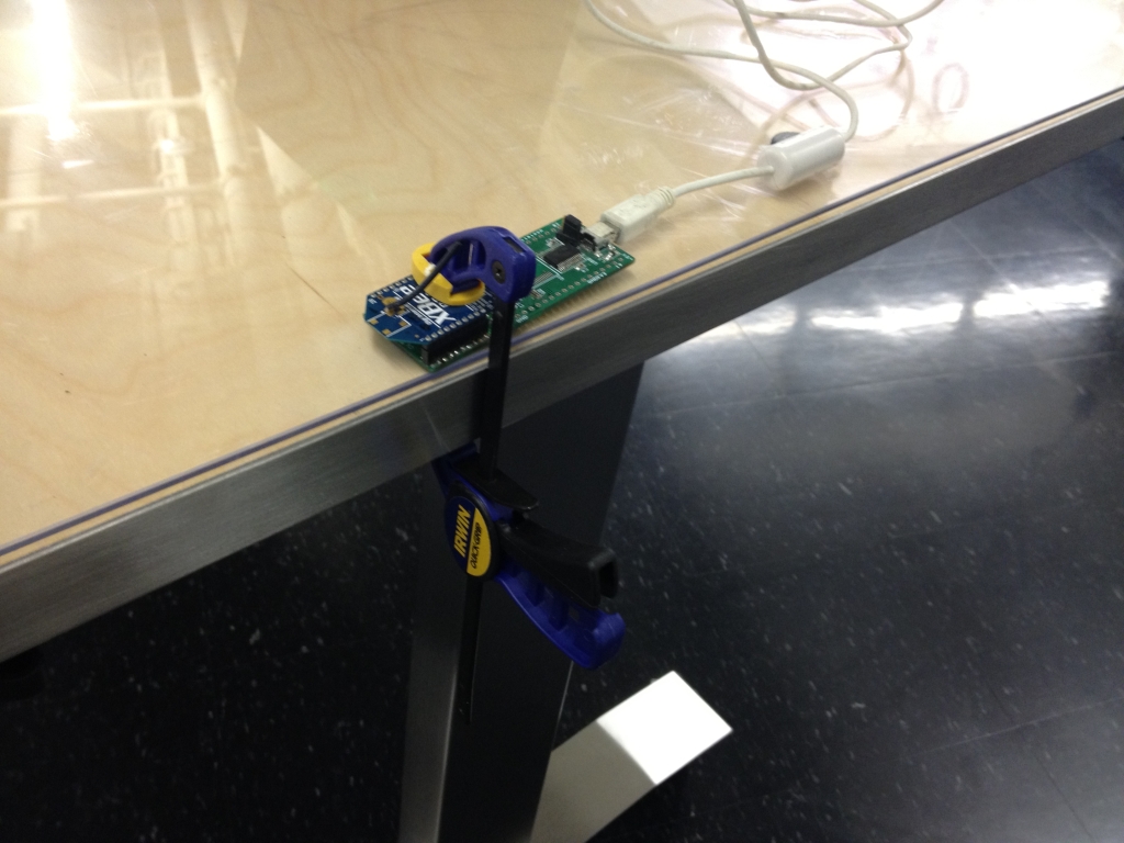
...unless you happen to work in a giant fishbowl with enough glass walls and doors to make you want to start writing equations on them in soap and muttering to yourself about secret codes hidden in your digital controls textbook. I set up my XBee receiver and data logging software so I could collect data from one of the six motor controllers. The XBee adapter board I use is rather old, though, and requires some manipulation to work properly:


At that point, I was all set to fly. Here's a video of the first couple of test hops:


In the first clip, the gains are a little on the high side, causing small oscillations which could go unstable when flying in ground effect or if a gust of wind disturbs the system. Turning the gains down made the flight less oscillatory, but also a little more jerky since the closed-loop tracking and attitude holding ability is reduced. 

I ran into a similar issue with Kramnikopter and the solution was to make the motor controller's input filter, which reduces noise on the PWM input from the KK board, faster. The faster filter had less lag and so the closed-loop system could tolerate a bit more gain without becoming oscillatory. With the CineStar motors, though, a faster filter has the potential to ramp the duty cycle so fast that the overcurrent protection is tripped, or the current sensors are saturated, either of which will cause a controller fault. 

In the test flight videos, the filter was a first-order discrete low-pass with a cutoff frequency of 5Hz. I will be trying some different types of filters, including a faster (10Hz) first-order low-pass and a non-linear slew rate limiter. I think the slew rate limiter might work best, since it attenuates large changes in input (ones that would cause overcurrent faults) but not small ones (like the closed-loop control signals).

For now, I got some good data on the operation of the ESCs. Here's the speed and current plots for the second of the two flight videos:


The hover speed is about 3700rpm for the 14x4.7SF props with a gross weight of about 4.76kg (10.5lb). The q-axis phase current for each motor is about 13A. I also installed a Watt Meter for the test hops. The average power draw for both flights was about 560W and the peak was about 630W. That's about 117W/kg average.

Here's a graph of the flux and phase currents vs. estimated rotor angle:


All the signals are in the right place, and it looks relatively clean. But there's definitely some bias in the flux estimate - it's shifted up by about 0.250mWb and the only thing keeping it from going further is the cap at 1.500mWb. This could be due to bias in the current sensors, so a self-zeroing start-up routine for them would probably help. Otherwise, a faster flux estimator filter would also hold the waveform in place better, at the expense of low-speed performance. So many tradeoffs... So much motivation to start working on Sensorless Gen2.

More testing to come.

Thursday, April 19, 2012

Sensorless Start-Up / Speed Control

It's spring demo season again. I'll be at the Cambridge Mini Maker Faire on Friday, along with the MITERS crew, with an assortment of projects. Come check it out. Follow-up post to come.

For now, time for a massive multi-controller update. The Sensorless, Sine-Commutated Field-Oriented Current Control (SSCFOCC) algorithm I've been working on has been sufficient abstracted now that I can develop for it on two different motor controllers (3ph v3.1 and FFv1.0) at the same time. (3ph v4.0 is coming soon and DirectDrive v1.0 still exists, I promise...)

Before I start developing new hardware and potentially writing a entirely different sensorless control algorithm, though, there were some loose ends I wanted to clean up in the current algorithm. Once these points are addressed, I will go back and write up a summary of my first-generation sensorless code since by now it's too complex for individual blog posts.

But First...


More Position Filtering

Loose End #1 was a problem with the rotor position estimating filter used to clean up the rotor angle at high speeds. I added this at the end of the last sensorless post and even though it immediately improved the high-speed performance of FFv1.0 on the hexrotor motors, there was a weird side-effect on the flux vs. angle graph. The flux estimate would begin to lead the rotor angle estimate at high speeds, which should not happen since the rotor angle estimate is derived from the flux estimate. The flux vs. angle curve should be constant. What the?

After staring at the code for a little while, I identified this a rather complex software error on my part tracing all the way back to a subtlety of BWD's sensored FOC code... I'll spare you the details, but I fixed it and now the flux estimate is much nicer:

Pneu Scooter w/ 3ph v3.1. Compare to unfiltered flux estimate.
Much of the "noise" from the 2d plot is shown to be offset at low speed (<200rpm).
Hexrotor motor with FFv1.0. Compare to the unfiltered flux estimate.
And in nauseating pseudo-3d.
The low-speed offset is a known issue having to do with the fact that the integrator at the heart of the flux estimate is implemented as a low-pass filter. There is also a phase offset in the flux estimate resulting from this practical non-ideality:


Since this is a known offset, it could potentially be subtracted off. Or the low-pass filter could be designed such that at the start-up routine exit speed, the offset is less than 15ยบ or so. For the data above, that would be about 150rpm. Speaking of start-up routines...

Start-Up

Loose End #2 was the lack of any start-up routine for either controller. I've been putting it off for a number of reasons. For one, Pneu Scooter really doesn't need a start-up routine. The sensorless algorithm has no trouble picking up the rotor speed at as low as 50rpm and that's well within single-kick speeds:

One kick gets to 75rpm, at which point the flux estimator has locked in.
Also, Pneu Scooter really doesn't have enough torque to justify a no-kick start-up routine. Even at peak current (40A), the acceleration is something like 150rpm/s. The sensorless start-up will achieve far less than peak torque, though, since it won't have the benefit of optimum current vector placement. So it could mean a couple seconds of balancing on a barely-moving scooter while the speed ramps up. It's just much more natural to kick start.

FFv1.0 and the hexrotor motors, on the other hand, almost definitely need a start-up routine. Even though in this video, a very large (14x4.7SF) prop starts cleanly and quickly with no start-up routine at all. The command PWM goes high enough that the motor is forced to do something, and by luck it gets kicked in the correct direction at sufficient speed for the flux estimator to lock in. But this is unreliable (works maybe 50% of the time) and inelegant, so it should really have a slow-ramping startup routine as well.

Maybe the real reason I haven't implemented a start-up routine yet is because it's easy. At least, the most obvious way of doing it is easy. Lacking position information, there isn't much choice in how to drive a brushless motor: it becomes a coarse stepper. Except with sinusoidal commutation it can be like a microstepping coarse stepper, which is still pretty smooth. The point is, the only way to drive it with no knowledge of the rotor position is to put current in somewhere and wait long enough to know that the rotor has most likely reached the position you told it to go to. With that in mind, I wrote a simple start-up routine with four states:
  1. IDLE: Wait at zero speed until the user commands a positive torque or speed.

  2. PARK: Place current vector at a fixed angle and wait for some time for the rotor to reach a stable position.

  3. RAMP: Rotate the current vector with a constant angular acceleration that is sure to be achievable by the rotor given the amount of current commanded and the estimated load inertia.

  4. RUN: After a certain speed, switch to sensorless field-oriented control using the rotor angle predicted by the flux observer.
The ramp state here differs a little from BLDC-style sensorless start-up routines that use six-step voltage-mode commutation. Since this ramp state is still current controlled, the possibility for variable user-commanded acceleration during "open-loop" start-up is present. The angular acceleration of the ramp is linked to the amount of current commanded. If you go light on the throttle, the ramp takes longer.

Since the load inertia can't be exactly known, the start-up ramp acceleration has to be conservatively chosen. The start-up torque will therefore be significantly less than the run torque, and the efficiency will be very low. This is a common trait of sensorless start-up algorithms and the best way to minimize the effect is probably to get out of start-up as soon as possible. Transitioning to closed-loop sensorless control at 5-10% of the maximum speed seems to be achievable.

Anyway, enough hypothesizing. Here is my first shot at a sensorless start-up for Pneu Scooter, the harder of the two challenges:


The ramp goes from 0 to 150rpm in about 3 seconds with 30A commanded current. This is about 50% of the acceleration that would be expected from closed-loop control, so it feels sluggish for the first three seconds. But, it is smooth and transitions cleanly to run-state closed-loop control at 150rpm. Making the ramp faster results in pole slipping, so this is about as good as it will get.

One option for improving the start-up is to get out of the ramp state earlier. The flux estimator is able to pick up the rotor movement at as low as about 25-50rpm, so waiting around until 150rpm sounds silly. But, the low-pass filter-induced phase lead is still very high at those speeds, so the transition doesn't work reliably. It's clear that the low-pass filter time constant and the ramp exit speed are coupled in this way. Something to think about for future optimization.

Another option is to use more current. This doesn't help the efficiency, but it will create a faster ramp. 60A for a short period of time shouldn't hurt the motor or controller, but I'll wait for 3ph 4.0 to test that.

Start-up for the hexrotor motors is a much simpler problem. For one, they have essentially no load at start-up when the prop is moving too slowly to create significant thrust or drag. The performance of the controller is also not at all dependent on low-speed torque characteristics since the minimum RPM seen in flight will be well above the run-state threshold. Here's a very light ramp (<5A) for the 14x4.7SF prop:


The threshold for transitioning from ramp state to run state is 600rpm, and once it transitions to run state the torque increases dramatically. The ramp can afford to be much faster without slipping poles, but for the purpose of reaching a safe idle speed for the prop, it almost doesn't matter. Note that the speed goes directly to idle speed, 1,000rpm, and sits there. That brings me to...

Speed Control

Loose End #3 is speed control for FFv1.0. Pneu Scooter, as a vehicle, is happy with current (torque) control. But for the hexrotor, the master controller may want to command an exact speed for each rotor. Speed is directly related to static thrust (though not linearly). Steady-state current is also related to static thrust (close to linearly). But with inertial transients to deal with, the performance of a speed-based controller might be better.

Actually, the simple way to do "speed" control is to directly vary the PWM duty cycle, bypassing the current control entirely. This controls speed because motor speed is approximately proportional to applied voltage, which is controlled by the PWM duty cycle. As it turns out, it's definitely possible with the modified Synchronous Current Regulator (mSCR) to use this control mode, bypassing the q-axis current controller but leaving the d-axis (phase) controller working. This gives the benefits of FOC (dynamically adjusted motor timing) but the simplicity of direct PWM control. In fact, this was what I used for the first few tests of FFv1.0. Here's some data showing it executing step "speed" commands:


At each step, the q-axis and d-axis current spike due to the inertia of the motor and prop. But, the back EMF brings the q-axis current back to a steady-state value as the prop speeds up or slows down, and the mSCR adds or subtracts from the phase to bring the d-axis current back to zero.

The benefits of direct PWM magnitude control are simplicity and robustness. With current limiting to prevent the spikes from damaging components, I think this could be a pretty good way to run a multirotor controller. It's how most ESCs operate, so it would feel normal. But, it has several downsides:

  1. It can't achieve minimum rise time. The step in voltage magnitude will give only as much current as the motor resistance will allow. A smarter controller could slew the motor faster using a voltage that is higher than the steady-state value at the target speed.

  2. It can't accommodate minor difference in motors/ESCs/props. If one motor is slightly weaker than the others, it will spin slower under PWM magnitude control. The master attitude controller's integral term can correct for this, but why rely on this?

  3. Motor speed is only roughly proportional to applied voltage. The actual speed depends on the back EMF, which is V-IR. At higher loads, the speed per applied volt is lower. Does this matter? Maybe not, since none of this is linearly proportional to thrust anyway.
A classical approach to true speed control would be to wrap an outer PID control loop around everything:


The speed control loop, a generic PID with saturation, feeds the q-axis current reference a value between the maximum braking current and the maximum accelerating current, depending on the speed error. The d-axis controller is still simply trying to maximized torque per amp by adjusting motor phase. (The more I think about it, the more the mSCR strategy makes sense in this regard.)

This video shows the start-up and PID-based speed control for FFv1.0 with the 14x4.7SF props:


The nice thing about PID control is that it's easy to understand and easy to tune. Unfortunately, the load in this case is very nonlinear. As the speed increases, the damping due to propeller drag goes up. So, the step response changes depending on the speed:

Real data from the 14x4.7SF prop.
From 1,000-2,000rpm, the chosen gains exhibit a lot of overshoot. From 4,000-5,000rpm, they're overdamped. With this data as a starting point, I made a quick simulation including the nonlinear prop load. Another nice thing about PID is that it's very easy to work with in a Simulink:

This is what grad students do all day.
After some shady parameter estimation, I could almost predict the step response shapes:


The real-life response is actually a bit faster than the simulated response, for some reason. Not going to complain about that. But, they're both pretty slow overall. The motors never reach peak current during speed steps. The slew rate can and should be much faster for the best possible speed command tracking. By tweaking the gains in Simulink, I can now get a feel for which way they should be pushed in real life to speed up the response and kill off some overshoot.

I also think there's a better way. This post is already quite long so I'll have to save that for next time, but there is a hint of it in the Simulink diagram...

For now, I leave you with a Kramnikopter that I bought for basically nothing and will be doing absolutely zero custom development for:

Yay, not-complicated flying things.

Sunday, April 1, 2012

TI Workshop + The Joys? of High-Speed Motor Control

I spent the past week at the Texas Instruments C2000 MCU Real-Time Industrial Control Training in Waltham, MA. It was really good workshop that I would highly recommend for anyone who wants to get into real time motor control. The next events are in Michigan and Wisconsin in May and June. The three-day event covers control theory on day 1, motor control specifics on day 2, and a C28x microcontroller intro on day 3, for which you get an F28069 Piccolo controlSTICK to keep:


In the interest of fair reporting, I will say the that feature set of the TMS320F28069 microcontroller does give it a few advantages over the STM32F103C4 that I currently use. It's a 32-bit processor (not ARM based) and can run at up to 80MHz. But, it has a built-in FPU and control-law accelerator, something not found until the F4 line of the STM32s. It also has more PWMs (16) and ADCs (16) than the smaller STM32F1s. As far as the available IDEs, I've used both IAR EW and Code Composer Studio before and I find them to be equally annoying. And I hate JTAG/emulated debugging anyway. 

I don't see myself switching away from the STM32, but I've had good experiences with the TI MSP430 line and I wouldn't hesitate to recommend those or the more powerful C2000's for people looking to escape from Arduinoland.

Since I'm always talking about how convenient it is to have a compact electric scooter that folds so you can take it on public transportation, I decided to try it out on my way out to Waltham. The bus from near me stops just on the other side of Prospect Hill Park from the TI offices:

No problem. This should be a nice traffic-free scooter ride through the pa-  
Oh.
I guess I neglected to consider the fact that Prospect Hill Park might actually be named for its predominant topographical feature. Pneu scooter is good at a lot of things, but hills are not one of them.

So I guess I'll be hiking.
Also, some of the paths are just dirt trails. The good news is that that's the TI parking lot right there.
Well at least I could have a fast trip down the hill on the way home - Oh no wait, it tore my brakes apart on the first two days. By the third day, with repaired brakes, I had pretty well optimized energy usage so that I could minimize hiking up the hill and coast the entire way down. Still better than driving in Boston rush-hour traffic.

Anyway, although all three days of workshop were great, I was especially interested in Dave (Wisconsin) Wilson's Motor Control Seminar. Most of the slides are available on his blog if you are interested. I learned a bit more about TI's InstaSPIN BLDC control scheme, and am beginning to sort out the various types of sensorless control methods.


One thing I picked up which I have to think more about is that what I have previously referred to as an open-loop flux estimator is in fact not as far different from a closed-loop observer as I had thought. The difference is more subtle and possibly less fundamental than it seems. For example, here is a closed-loop single-phase back EMF/current observer with a PI compensator:


With just one page of math, I can unwrap the feedback loop and rewrite it in the form of my "open loop" flux estimator, plus an additional low-pass filter. The closed-loop form still has the advantage of keeping an internal state for current estimate, which is probably way cleaner than the measured current. But they're not fundamentally different as I had once thought. Go figure... 

Maybe the important distinction then isn't between open-loop and closed-loop formulation for the observer. Maybe the fundamental difference is between observers that work only on electrical quantities and ones that include a mechanical state (speed, position). The addition of a mechanical state would almost certainly improve the performance of either observer, since it would anticipate the trajectory of I and E as the motor rotates. No wonder this is the type of observer described in the Book of Mevey, which has been right about everything else so far.

Back to reality.

My immediate task is to get this thing spinning:


After realizing that I wouldn't be able to hear anyone coming over the noise of the propeller, I added this:


In the previous post, I had gotten FFv1.0 up and running using Pneu Scooter as a test motor. The TI DRV8301 gate driver/everything chip performs well. But, the first time I attempted to run the motors on the hexrotor, I ran up against some not entirely unexpected issues with high speed control. At full speed, the electrical frequency of these motors can be 1,000Hz or higher. Every part of the control loop from the currrent sensors to the digital filters has to keep up with this, and in fact exceed it by a large margin to minimize phase lag. This is a tall order with a 15.625kHz PWM-limited control loop.

What I found on the first attempt is that at high speeds, the flux estimate becomes noisy and its zero-crossings, which are used to mimic Hall effect sensor transitions in my sensorless method, become blurry and unreliable. As a result, the position estimate would become noisy, which would lead to incorrect voltage vector placement. This leads to even more noisy current which leads to an even more noisy flux estimate, and so on. The physical result would be a motor that sounded very unhappy and current measurements that are all over the place starting at just under 5,000rpm. Under load, it could lose sync and crash entirely, surviving only because it was running on a current-limited power supply.

As an attempt to remedy the problem, I'm trying an idea I first thought of a long time ago for use with Hall effect sensor-based field-oriented control. The algorithm already uses a time-based interpolator to work between one flux zero crossing (or Hall effect transition) and the next. Instead of trusting the new zero crossing's position estimate 100% of the time, it's possible to use an IIR-style filter to merge the interpolator with the new position. Maybe this will help:

Maybe.
When the new flux zero crossing or Hall effect sensor transition comes in, it generate an angle (blue) which previously would be taken as the true angle. Now, that blue angle is averaged with the current estimate based on time interpolation (brown) to create the new estimate (purple). The relative degree of weighting for the average is set by a parameter, A, just like and IIR filter.

At high speed, when the blue vector is popping up at the wrong time due to noise, this filter will help stabilize the rotor angle estimate. And what a difference it made, without any tuning whatsoever. Here's some video of spinning up the larger prop, a 14x4.7SF:


One interesting thing is that I haven't even written a startup routine yet, but most of the times it starts just fine. I guess I'm used to vehicle controllers where if you don't write a startup routine they just sit there and buzz angrily. Also interesting is that once it does start, it can run at as low as 370rpm, which is about 7.5% of the top speed. So that would be my target speed for exiting the startup routine and entering run mode.

I can tell from the data that the angle filter helped a lot - the current is much cleaner. Here's a plot of the flux and phase currents with respect to the estimated angle:


Things are mostly in the right place and the flux estimate has the correct magnitude. (The flux is related to the motor constant or the rpm/V constant.) Something fishy is going on with the phase of the flux estimate. Its peak should stay right on 180ยบ, since that's being used to define the d-axis. But instead it starts to shift forward at high speeds. As it turns out, I messed up the filter code a bit, so I'll have to go back and fix this one later.

For now, I also did some benchmarking against a Turnigy Sentilon 100A HV, a very good brushless motor controller. I measured (using a clamp multimeter) the AC RMS phase current and the DC bus current at different speeds running with the Sentilon 100A HV and with FFv1.0:


The not-very-interesting result is that they pretty much overlap so far. So I am at least not doing worse then good-but-dumb brushless DC controllers. It's definitely possible that any advantage of FOC will be lost in these motors because they are so efficient in BLDC mode already. Typically, high-speed low-inductance motors can operate very well with square wave drive. 

But there are other advantages that I'm still counting on. One which I was reminded of accidentally is that this controller can do four-quadrant drive. It can, in fact, brake so hard that it can unscrew the prop adapter and send a propeller flying across the room. Having braking should improve the response time of the motors to negative speed steps, which can help the control be snappier.

I've only just barely scratched the surface of the number of parameters that can be tuned. My next task will be to explore the effects of changes to the various motor parameter estimates, the filters, and the limits. Then, to see how it responds to more dynamic inputs. Then collapse everything into a simple enough interface that it could be used by other people. But so far, it's been a relatively problem-free controller build for once...

Wednesday, February 8, 2012

Flying Things Update

Even though I haven't made any significant changes to 4pcb, I still feel compelled to dump the latest media into a post and update briefly on some of the other (other?) flying things. But first, some recent flying things that are not mine but are too awesome to ignore:

Cinestar 3-Axis Gimbal (Snow): Watch this in HD, with huge speakers. Now. It's impossible to explain in words how amazing it is. This is the Cinestar 8 with a 3DOF camera mount.

A Swarm of Nano Quadrotors: This was viral, so you may have seen it already. The Aggressive Maneuvers group from UPenn's GRASP Lab has released their newest video, which is near and dear to my heart because it uses nano quadrotors.

Nanocopter: Based on the OpenPilot platform, this one of the smallest quadrotors ever made. It's way smaller than 4pcb (2/3 the size and 40% the weight). The challenge is also issued for anyone to make a picocopter with 2" props.

Tricopter: A tricopter is an interesting controls problem, because it requires at least one servo to give it independent yaw control. This one is particularly light and stable, and has gone through many iterations to get better and better.

Tinycopter: Kinda like a a 5/4-scale 4pcb. Except it uses standard off-the-shelf components so you could build one without the need for a custom circuit board and surface mount soldering skills. Speaking of Tinycopter, I got a chance to do battle against the original Tinycopter:


The thing I learned is that there really isn't a winning strategy in Battle Quadrotors. Anyway, the miniature and nano-scale quadrotors tend to be very robust, so neither suffered major damage. Which got us thinking: what would it take to kill a miniature quadrotor?


Oh...that'd do it. The Tesla coil, built by Daniel K., emits enough EMI-inducing field to mess with sensors and possibly even radio control, but that's if it doesn't simply strike your airframe with an arc instead.

Sticking with the theme of destruction, there was a brief period of nice weather (nice = 45ยบ and not windy) where I was able to fly one of my new flying things, a Hacker Skyfighter from Ryan A. I have only ever flown a small, ultra-stable indoor plane, so this was going to be an interesting challenge.


It's a flying wing, and set up for aerobatics. So if it looks like I know what I'm doing, rest assured this plane cannot help but do loops, rolls, and various other stunts while I try frantically to point it upwind and fly it away from the running track and back to the baseball field where I started. But, I will practice more and one day be good enough to actually land it.

I'm sorry, Ryan.
For now, though, back to multirotors. 4pcb has always been plagued by frame vibration issues, since it's made only from 0.063" FR4. I can see the props and motors wiggling when the frame hits resonance, and it certainly messes with the gyro readings and makes it more difficult to fly. Through a combination of mechanical and software measures, I've made the control mostly immune to these vibrations, but I thought it would be interesting to try to see the magnitude of the problem more directly.

To visualize the vibrations, I used a trick I've used before, strobe imaging. Ordinarily, you can set the strobe light to flash at the same speed as the rotating object and it will look stationary. But, you can also offset the strobe by a small amount in order to get a virtual slow-motion action shot. For example, if the props are spinning at 6000rpm (100Hz), setting the strobe to 101Hz will cause them to appear to spin (backwards) at 1Hz. Since the props create the forcing frequency that drives the frame, the vibrations should also be visible at 1Hz. Commence magic:


There are definitely at least two modes of vibration present. The first, which occurs at lower frequency, is a torsional mode where the arm twists. The second, a higher-frequency mode, is the arm bending up and down. The twisting mode looks more dramatic, and I would probably want to minimize its magnitude first to get the cleanest inertial measurements. I actually tried adding carbon fiber reinforcements:


This definitely stiffened up the frame, but it didn't actually fly better. For one, I've mostly solved the gyro noise problems already, so any gain achieved by reducing vibration will be marginal at this point. Additionally, the extra weight and airflow disruption from these supports may have been enough to push some of the motors closer to saturation, making the control feel softer. So I took them off.

In general, 4pcb's motors are running too close to the control limit (hover is just under 200 out of 250 on the throttle at full battery voltage). I replaced one motor that had bad bearings, and the motor I put in its place was weaker than the other three and saturated the control output all the time. After a day of troubleshooting, I swapped the motor yet again and now they are more well-matched. Still, when the battery begins to get low, one motor will saturate and cause it to feel very soft and drifty.

Unlike most of my project chains, v1.0 of this quadrotor has been very successful and I'm quite happy with the way it works now. But I'm looking forward to improving it a bit more and it's up to the point where I will need a new board revision to do so. The next version of the PCB quadrotor will have several improvements including:
  • Lighter weight. Microcontroller and power wiring integrated onto the board.
  • Higher voltage (11.1V instead of 7.4V). This will help with command saturation, giving more thrust margin for the 2000rpm/V motors, and keep the voltage away from the Toshiba chip's 7.0V minimum. To maintain the weight goal, it will have to be a lower capacity. But with a higher input voltage, the ESCs will draw less battery current, so flight time should be similar.
  • Closed-loop velocity control. No more motor matching. The Toshiba chips have a tachometer output that can be used as feedback to control prop speed, instead of open-loop motor terminal voltage.
  • It will also have provisions for altimetry and possibly a small camera mount.
I'm not sure when I'll get around to that revision, but for now, here's some fantastic processor-eating 1080p video of 4pcb v1.0 in action, thanks to Sherry W.:


There's also something interesting in the background of that video, and I posted a teaser a few posts ago:


I'll apparently be going directly from miniature quadrotor to giant freaking hexrotor without stopping in between. (Okay, there was this medium-small quadrotor I helped out with a while back.) But anyway, thanks to a donation from some very awesome people, I now have a Cinestar 6 frame, with motors. This is the six-rotor cousin of the Cinestar 8 from the snow video above. I am planning to use it as a development platform for custom ESCs in the near future. But for now I will be working with some people to get it flying with off-the-shelf hardware. Step one for me was a quick thrust test:


Yes, that is one of Cap Kart's old batteries being used as ballast while a 12" prop tugs on a spring scale. Note also the 80/20 bar blocking the hexrotor from doing a complete flip in the event of string breakage. The result was a thrust of about 2kg at max current with a 12x3.8SF prop. That's 10x the amount of peak thrust 4pcb puts out from all four of its props...

The frame + motors weighs 1.5kg. So even after adding in the props, ESCs, control board, and a reasonably-sized battery, it has enough thrust to carry some pretty epic payloads... I am both terrified and excited to see it flying.

Wednesday, December 28, 2011

4pcb: √ Control Law + Teaser...

Yes, I am making another post about quadrotors. A made a few minor tweaks to the control of 4pcb. The most notable is a change to the output command for each motor, after all the P[I]D controller and motor mapping. The commands are now sent through a square root function. The force produced by the props is more related to rotational speed squared than to rotational speed. The speed is roughly proportional to the command. So, to produce a corrective a force, as the PID controller would like to do, the command generated in response to angle or rate error should follow a square root-type curve. Or so the story goes.

The remap sends the command through a square root function while normalizing to 1, to preserve the command range. Something like this:

// square root remap, command range is 0-255:
command_out = 255.0*sqrt(command_in/255.0);

This keeps the maximum command at 255 and the minimum at 0, but shapes the intermediate values to be a square root function. I don't actually do it like this because square root on a microcontroller is a horrible thing. Both the input and the output are 8-bit integers, and I have plenty of memory, so I use a look-up table instead:

// I'm a horrible person, generating my LUT at run-time:
unsigned char SQRT_LUT[256];
for(unsigned int i = 0; i <= 255; i++)
{
  SQRT_LUT[i] = (unsigned char)(255.0*sqrt((float)i/255.0));
}

...and later, in the loop...


command_out = SQRT_LUT[command_in];

Because it's an 8-bit integer table, there is some quantization near the extremes, but my upper and lower throttle limits (100 and 230) constrain it to a well-behaved part of the curve:


After implementing the remap, I noticed a significant improvement in the performance. For one, some of the high-frequency oscillation is gone. It doesn't seem to wiggle back and forth quickly when it's just hovering. It's also easier to hold it at a given altitude, probably due to the more linear stick-to-force relationship. I don't think it's just placebo effect, but who knows?

I also made one other ugly hack. One motor has been consistently and annoyingly slow compared to the other three, causing the roll axis to be hard to fly, especially as the battery drops below about 7.4V. I just multiplied this motor's rate gain by 1.3. I have no justification for this value, but it helps. Maybe I will replace that motor and ESC at some point. Here's some new video:


I can keep it in the air indefinitely in a small room, as long as the battery is above 7.4V. Below 7.4V, the roll axis still gets soft and it's hard to not crash into things. So for now I live with flying just a bit more than half the battery capacity. Even Charles can kinda fly it now. So it must be a little more stable.

The two hardest parts about flying it are maintaining altitude and remembering which way it's pointed. While I think you can learn to deal with both of these, I would like it to be easy enough for anyone to pick up and fly. I have, waiting to be installed, a sonar module that can be used for closed-loop altitude control. Then, the stick would control a climb rate or descent rate, but with no input it would hold altitude and you can focus on flying the rotational axes. I also have yet to implement the magnetometer on the new IMU, which can be useful for holding heading so you don't have to deal with yaw.

I really shouldn't be spending this much time on quadrotors, though. I'm pretty sure I had other things I was supposed to be working on. On that note...

......