Showing posts sorted by date for query maker faire. Sort by relevance Show all posts

Sunday, December 28, 2014

Fun with Pixel Shaders

One of the things that saved my ass for MIT Mini Maker Faire was SlimDX, a modern (.NET 4.0) replacement for Microsoft's obsolete Managed DirectX framework. I was only using it to replace the managed DirectInput wrapper I had for interfacing to USB HID joysticks for controlling Twitch and 4pcb. For that it was almost a drop-in replacement. But the SlimDX framework also allows for accessing almost all of DirectX from managed .NET code.

I've never really messed with DirectX, even though at one point long ago I wanted to program video games and 3D stuff. The setup always seemed daunting. But with a managed .NET wrapper for it, I decided to give it a go. This time I'm not using it to make video games, though. I'm using it to access GPU horsepower for simple image processing.

The task is as follows:

The most efficient way to capture and save images from my USB3.0 camera is as raw images. The file is a binary stream of 8-bit or 12-bit pixel brightnesses straight from the Bayer-masked sensor. If one were to convert these raw pixel values to a grayscale image, it would look like this:

Zoom in to see the checkerboard Bayer pattern...it's lost a bit in translation to a grayscale JPEG, but you can still see it on the car and in the sky.


The Bayer filter encodes color not on a per-pixel basis, but in the average brightness of nearby pixels dedicated to each color (red, green, and blue). This always seemed like cheating to me; to arrive at a full color, full resolution image, 200% more information is generated by interpolation than was originally captured by the sensor. But the eye is more sensitive to brightness than to color, so it's a way to sense and encode the information more efficiently.

Anyway, deriving the full color image from the raw Bayer-masked data is a bit of a computationally-intensive process. In the most serial implementation, it would involve four nested for loops to scan through each pixel looking at the color information from its neighboring pixels in each direction. In pseudo-code:

// Scan all pixels.
for y = 0 to (height - 1)
 for x = 0 to (width - 1)
  
  Reset weighted averages.  

  // Scan a local window of pixels.
  for dx = -N to +N
   for dy = -N to +N
    
    brightness = GetBrightness(x+dx, y+dy)
    Add brightness to weighted averages.
   
   next
  next

  Set colors of output (x, y) by weighted averages.

 next
next

The window size (2N+1)x(2N+1) could be 3x3 or 5x5, depending on the algorithm used. More complex algorithms might also have conditionals or derivatives inside the nested for loop. But the real computational burden comes from serially scanning through x and y. For a 1920x1080 pixel image, that's 2,073,600 iterations. Nest a 5x5 for loop inside of that and you have 51,840,000 times through. This is a disaster for a CPU. (And by disaster, I mean it would take a second or two...)

But the GPU is ideally-suited for this task since it can break up the outermost for loops and put them onto a crapload of miniature parallel processors with nothing better to do. This works because each pixel's color output is independent - it depends only on the raw input image. The little piece of software that handles each pixel's calculations is called a pixel shader, and they're probably the most exciting new software tool I've learned in a long time.

For my very first pixel shader, I've written a simple raw image processor. I know good solutions for this already exist, and previously I would use IrfanView's Formats plug-in to do it. But it's much more fun to build it from scratch. I'm sure I'm doing most of the processing incorrectly or inefficiently, but at least I know what's going on under the hood.

The shader I wrote has two passes. The first pass takes as its input the raw Bayer-masked image and calculates R, G, and B values for each pixel based on the technique presented in this excellent Microsoft Research technical article. It then does simple brightness, color correction, contrast, and saturation adjustment on each pixel. This step is a work-in-progress as I figure out how to define the order of operations and what techniques work best. But the framework is there for any amount of per-pixel color processing. One nice thing is that the pixel shader works natively in single-precision floating point, so there's no need to worry about bit depth of the intermediate data for a small number of processing steps.


The second pass implements an arbitrary 5x5 convolution kernel, which can be used for any number of effects, including sharpening. The reason this is done as a second pass is because it requires the full-color output image of the first pass as its input. It can't be done as part of a single per-pixel operation with only the raw input image. So, the first pass renders its result to a texture (the storage type for a 2D image), and the second pass references this texture for its 5x5 window. The output of the second pass can either be rendered to the screen, or to another texture to be saved as a processed image file, or both.

What a lovely Seattle winter day.
Even though the pixel shader does all of the exciting work, there's still the matter of wrapping the whole thing in a .NET project with SlimDX providing the interface to DirectX. I did this with a simple VB program that has a viewport, folder browser, and some numeric inputs. For my purposes, a folder full of raw images goes together as a video clip. So being able to enumerate the files, scan through them in the viewer, and batch convert them to JPEGs was the goal.

Hrm, looks kinda like all my other GUIs...

As it turns out, the pixel shader itself is more than fast enough for real-time (30fps) processing. The time consuming parts are loading and saving files. Buffering into RAM would help if the only goal was real-time playback, but outputting to JPEGs is never going to be fast. As it is, for a 1920x1200 image on my laptop, the timing is roughly 30ms to load the file, an immeasurably short amount of time to actually run both pixel shader passes, and then 60ms to save the file. To batch convert an entire folder of 1000 raw images to JPEG, including all image processing steps, took 93s (10.75fps), compared to 264s (3.79fps) in IrfanView.

Real-time scrubbing on the MS Surface Pro 2, including file load and image processing, but not including saving JPEGs.

There are probably ways to speed up file loading and saving a bit, but even as-is it's a good tool for setting up JPEG image sequences to go into a video editor. The opportunity to do some image processing in floating point, before compression, is also useful, and it takes some of the load off the video editor's color correction.

I'm mostly excited about the ability to write GPU code in general. It's a programming skill that still feels like a superpower to me. Maybe I'll get back into 3D, or use it for simulation purposes, or vision processing. Modern GPUs have more methods available for using memory that make the cores more useful for general computing, not just graphics. As usual with new tools, I don't really know what I'll use it for, I just know I'll use it.

If you're interested in the VB project and the shader source (both very much works-in-progress), they are here:

VB 2012 Project: RawView_v0_1.zip
Built for .NET 4.0 64-bit. Requires the SlimDX SDK.

HLSL Source: debayercolor.fx

P.S. I chose DirectX because it's what I have the most experience with. (I know somebody will say, "You should use OpenGL.") I'm sure all of this could be done in OpenGL / GLSL as well.

Sunday, October 19, 2014

MIT Mini Maker Faire 2014

I made a quick trip back to Boston/Cambridge for the first ever MIT Mini Maker Faire. Recap and pictures below, but first here is some video from the event:


As expected from an MIT Maker Faire, there were lots of electric go-karts, Tesla coils, 3D printers, robots, and...

Chainsaw...pink scooter...things.
To this I contributed a set of long-time Maker Faire veteran projects (Pneu Scooter, 4pcb, Twitch) and a couple of new things (Talon v2 multirotor, Grasshopper3 Camera Rig). I always like to bring enough projects that if some don't work or can't be demonstrated, I have plenty of back-ups. Fixing stuff on the spot isn't really possible when you have a constant stream of visitors. But I've been to a number of Maker Faires and decided the maximum number of projects I can keep track of is five. Especially since this time I had to be completely mobile, as in airline mobile.

Arriving at the venue, MIT's North Court, luggage in the foreground, MIT Stata Center in the background.
The travel requirement meant that, unfortunately, tinyKart transport was out. (Although it is theoretically feasible to transport it for free via airline except for the battery and the seat...) But Pneu Scooter is eminently flyable and in fact has been all over the world in checked baggage already. It collapses to about 30" long and weighs 18lbs. The battery is well within TSA travel limits for rechargeable lithium ion batteries installed in a device. Oh, and Twitch fits right between the deck and the handlebar:

It was definitely designed that way...
Pneu Scooter and Twitch are really all I should ever bring to Maker Faires. They are low-maintenance and very reliable; both have survived years of abuse. In fact, Pneu Scooter is almost four year old now...still running the original motor and A123 battery pack, and still has a decent five-mile range. (I range-tested it before I left.) It's been through a number of motor controllers and wheels though. Because the tires are tiny, it's always been a pain in the ass accessing the Schrader valves with normal bike pumps. Turns out it just took five minutes of Amazon Googling (Is that a thing?) to solve that problem:

Right-angle Schrader check valve. Why Have I not had this forever?
Pneu Scooter survived the rainy Faire with no issues - it's been through much worse. I participated in the small EV race featuring 2- and 3-wheel vehicles. Unfortunately I didn't get any video of it, but Pneu Scooter came in third or something...I wasn't keeping track and nobody else was either. Mostly I was occupied by trying to avoid being on the outside of the drift trike:

Yes, those red wheels are casters...
But if I had to pick one project that I could pretty much singly count on for Maker Faire duty, it's Twitch.


Despite the plastic Vex wheels, Twitch has been pretty durable over the years. I had planned to spend a few days rebuilding it since I thought one of the motors was dead, but when I took it off the shelf to inspect, it was all working fine. In fact, the only holdup for getting it Faire-ready was that the Direct Input drivers I have been using since .NET 1.0 to read in Twitch's USB gamepad controller are no longer supported by Windows 7/8. Yes, Twitch outlasted a Microsoft product lifecycle... Anyway, after much panic, I found a great free library called SlimDX that offers an API very similar to the old Managed Direct X library, so I was back in action.


Basically, Twitch is an infinite source of entertainment. I spent a lot of the Faire just driving it around the crowd from afar and watching people wonder if it's autonomous... I would also drive it really slowly in one orientation, wait for a little kid to attempt to step on it (they always do), and then change it to the other orientation and dart off sideways. And then there is just the normal drifting and driving that is unlike any other robot most people have seen. I found an actual use for the linkage drive too - when it would get stuck with two wheels on pavement and two wheels on grass, it was very easy to just rotate the wheels 90º and get back on the walkway. Seattle drivers need this feature for when it snows...


Twitch is definitely my favorite robot. Every time I take it out, it gets more fun to drive. I have 75% of the parts I need to make a second, more formidable version... This Maker Faire was enough to convince me that it needs to be finished.

4pcb was a bit of a dud. I don't know if my standards for flying machines have just gotten higher or if it always flew as bad as it did during my pre-Faire flight test. It still suffers from a really, really bad structural resonance that kills the efficiency and messes with the gyros.


It was one of the first, or maybe the first PCB quadrotor with brushless motor drivers. But the Toshiba TB6588FG drivers are limited in what they can do, as is the Arduino Pro Mini that runs the flight control. Basically, it's time for a v2 that leverages some new technology and also improves the mechanical design - maybe going to 5" props as well. We'll see...

And unfortunately, because of the rain and crowds, I didn't get to do any aerial video with my new Talon copter. But it looks good and works quite nicely, for a ~$300 all-up build. (Not including the GoPro.) Here's some video I shot with my dad in North Carolina that I had queued up to show people at the Faire.

Talon v2, son of Kramnikopter.
Electric linkage drive scooter drone...fund my Kickstarter plz.
The last thing I brought for the Faire was my Grasshopper 3 camera setup with the custom recording software I've been working on for the Microsoft Surface. With this and the Edgerton Center's new MōVI M5, I got to do a bit of high speed go-kart filming and other Maker Faire documentation. The videos above were all created with this setup.

I had a stand, but this seemed easier at the time...
As a mobile, stabilized, medium-speed camera (150fps @ 1080p), it really works quite nicely. I know the iPhone 6+ now has slow-mo and O.I.S., but it's way more fun to play with gimbals and raw 350MB/s HD over USB3. Of course it meant I had 200GB of raw video to go through by the end of the Faire. I did all of the video editing in Lightworks using a JPEG timeline. (Each frame is a JPEG in a folder...somehow it manages to handle this without rendering.)


And that's pretty much it. It was much like other Maker Faires I've been to: lots of people asking questions with varying degrees of incisiveness ("Is that a drone?"), crazy old guys who come out right before the Faire ends to talk to you about their invention, and little kids trying to ride or touch things that they shouldn't be trying to ride or touch while their parents encourage them. Although I did get one or two very insightful kids who came by on their own and asked the most relevant questions, which gives me hope for the future. It was great to return to Cambridge and see everyone's cool new projects as well.

My MIT Maker Faire 2014 fleet by the numbers:
Projects: 5
Total Weight: ~75lbs
Total Number of Wheels: 6 (not including omniwheel rollers)
Total Number of Props: 8
Total Number of Motors: 18 (not including servos), 1 of my own design
Total Number of Motor Controllers: 18 (duh...), 16 of my own design!
Total Number of Cameras: 2

And here are some more pictures from the Faire:

Clearscooter...
I'm not sure what this is.
Dane's segboard, Flying Nimbus, which I got to ride. It actually has recycle Segstick parts!
Good old MITERS, where you can't tell where the shelves end and the floor begins!
Ed Moviing. I finally figured out a good way to power wireless HD transmitters...can you see?
A small portion of the EVs, lining up for a picture or a race or something.
Of course there were Tesla coils.
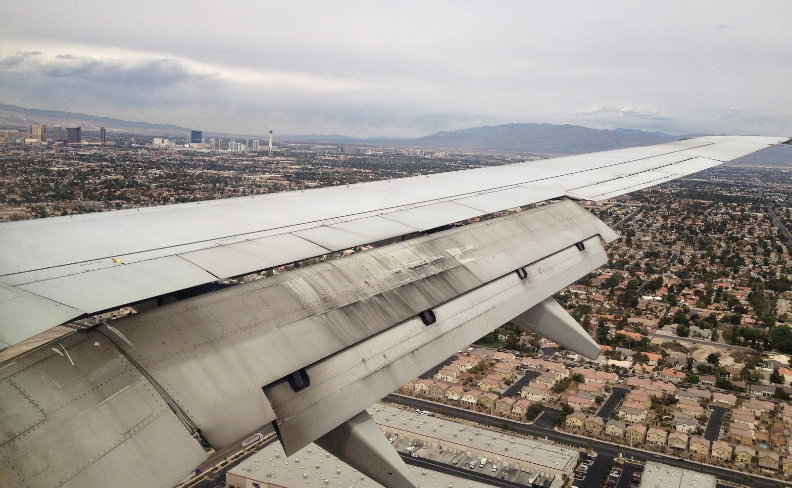
Flying out of Boston after the Faire, got a great Sunday morning view.

Sunday, April 13, 2014

NAB Show 2014

This year was my second trip to the National Association of Broadcasters exhibition (NAB Show) in Vegas as part of the Freefly Systems setup and pit crew. NAB is a huge (~93,000 attendees) expo for media technology, kind of like CES but for the Producers rather than the Consumers. In fact it's in the same venue as CES, the Las Vegas Convention Center.


Last year, the MōVI gimbal debuted and I think I explained the concept of active stabilization (one I can't seem to escape no matter where I end up) to a thousand different people in four days. This year, I didn't even have time to count the number of other handheld active stabilizers there were at the show. Certainly the gimbal trend has taken hold and there is no going back now.

The Birdy Cam!
I think the MōVI brand still holds the top end of the active stabilizer market (highest performance and, yes, highest price). I haven't used and won't ever use this blog for advertising - I'm not good at it anyway - but one big advantage Freefly had was a one-year head start during which some really spectacular footage was created by ever-more-skillful operators, and it's fun to see the results.

One of the event highlights was this interview with Tabb (Freefly president) and Garret Brown, inventor of the Steadicam. I felt like there should be some lighting bolts for dramatic effect given the "Steadicam-killer" hype surrounding handheld gimbals. But in actuality, the point made is an important technical one: active stabilizers control {pitch, roll, yaw}. There are still three degrees of freedom {x, y, z} that are at the mercy of the operator's movement, and Steadicam and its operators have perfected the smoothing of translation over the last 40 years.

Part of the fun of NAB is that I finally get to show off what I've been working on. My big project for this NAB was the EE/software for the new MōVI Controller, possibly the most hardcore-looking RC transmitter in existence:

My pet project, the blue OLED display. (The one on the unit itself, not the SmallHD monitor...) Anti-aliased font support, bitmaps, bar graphs, scrolling, string and numeric formatting, etc., all in a lightweight display driver written from scratch.
The station I somehow ended up manning at NAB: the new controller paired with the largest MōVI, the M15, and the Sony F55, rigged with wireless video and remote focus.
People trying out the new controller. Controlling framing and focus at the same time would take some practice, I think, and there is still the option of having a third operator control focus.
This was a hands-on demo; anyone could walk up and try it out. On one hand this was great, because it means I don't have to hold it the entire time (it was about 18-19lbs, total). But on the other hand, as my Maker Faire experience has informed me, it also means constantly watching the equipment, making sure it stays operational, changing batteries, and reminding people to share...all while trying to answer questions. And of course while most people are very respectful of the hardware, there are the expo trolls who go from booth to booth trying to break things.

In general, booth ops went much more smoothly this year, I think, due to a combination of better preparation and more manpower. There were a few other new toys to keep people engaged as well:

A Zero FX electric motorcycle with a Steadicam arm and M15 gimbal attached to the back. It seems I can't escape electric motorcycles no matter where I end up, either.
The Tero, a 1/5th-scale camera car, made a return as well. It's carrying an inverted M10 gimbal and Blackmagic 4K Production Camera.
Because our hardware was working well, and because we had enough people in the pits to handle the traffic, I actually got to wander around the show floor this year. There was a lot of camera porn, for sure. The Sony a7S was one of the big announcements, a small camera with supposedly epic low-light performance thanks to a full-frame 35mm sensor with just enough huge, gapless pixels for 4K video. On the other end of the size spektrum, AJA and Blackmagic also announced new, relatively inexpensive, 4K professional cameras.

The Blackmagic URSA. I can't get over how nice the machining is. On the other side is a 10" 1080p monitor.
I also went in search of the large active stabilizers - the ones that are mounted to full-size helicopters and camera cars for just about every aerial or car chase scene in a movie ever. There were three that I found at the show this year:

Filmotechnic, camera car specialists, with the Russian Arm and Flight Head active stabilizer (not sure exactly which one).
Shotover K1 full-size helicopter gimbal. This was about twice as large as I thought it was.
Cineflex, about the size I thought it was, but attached to a 27'-wingspan RC plane! Ryan Archer gogogogogo.
Cineflex ATV with one mounted in front and another in back.
A few other random sights of the show:

Crab drive (Or is it Swerve Drive? I can never remember the distinction.) FIRST robot camera dolly.
The circular equivalent of energy chain.
EditShare Lightworks, a powerful and relatively inexpensive video editing tool that I discovered at last year's NAB and have been using since.
Cutaway of a Canon lens...not sure how this even exists.
So yeah, these were just some of the things I saw at the show this year. It's definitely a bit of a circus, with a lot of money spent on impressive booths (and yes, sadly, in this day and age, booth babes are still a thing).

Booth cars I can understand.
Ignoring the flashy bullshit is hard, but underneath there is some cool tech on display and that's mostly what I like to see. Active stabilizers, wireless HD video, less and less expensive high-quality video cameras, more accessible software, etc., all make for an exciting media era - one for which I will happily hide on the engineering side.

Tuesday, September 24, 2013

tinyKart Black

tinyKart is back, in black:


The last time I saw tinyKart in one piece was almost a year ago at Maker Faire NY 2012, where it was torn apart in the name of impromptu power wheels racing, including 50 or so rain-soaked endurance laps after it had already lost an entire side worth of drive and brakes in two crashes. To be fair, it was already beat up from a couple years of abuse, off-roading, snow rallying, more snow rallying, and parking garage climbing.

It was certainly not built with this in mind.
I'm actually amazed it lasted as long as it did. It was originally designed as an ultralight go-kart, one that was not a burden to move around and that took advantage of modern electric motor and battery technology instead of loading up on lead, copper, and steel like certain other go-karts. It more than fulfilled its mission in that it was not only as light and portable as envisioned, but also more powerful and fun to drive than we thought it might be given the weight compromises.

If anything, it's weight-saving tradeoffs became secret advantages: chassis flex from the aluminum extrusion frame helps keep all four wheels in contact with the ground; narrow tires match the weight and power to give it a nice, predictable traction envelope. The result was that, somewhat to my surprise, I actually wound up liking the way it drove a lot more than Cap Kart, which was more of a no-nonsense, high-power, infinite traction machine. And unlike Cap Kart, we could take it out whenever we wanted since it serves as its own hand truck.

So I was sad to see it broken and in pieces for so long. Though, it did make it easier to package for shipping to Seattle when I moved out in this direction:

Picture frame box? You mean go-kart box?
Anyway, it's been a long, slow process putting it back together. Mostly because every time I would strip down another layer, I would discover another problem. It essentially came to breaking down the entire kart and rebuilding it from scratch, replacing parts as needed. And since I would have it down to atomic pieces anyway, why not paint it? Except I suck at painting things so pretty much the only color I could pull off would be flat black. Turns out to be a pretty good color anyway.

But first, an assessment of the post-Maker Faire 2012 (and indeed two year sum total) damage that it stared with:
Bent front frame plates, bent front-right spindle shaft, necessitating brake caliper removal.
Bent front frame on the other side. We were originally thinking of leaving these corners off...glad we didn't.
Bent spindle shaft and steering linkage.


As I stripped parts off, I found more and more damage:

Drive pulleys essentially destroyed. One belt had changed itself from a toothed belt to a flat belt with help from a corner of the motor mount.
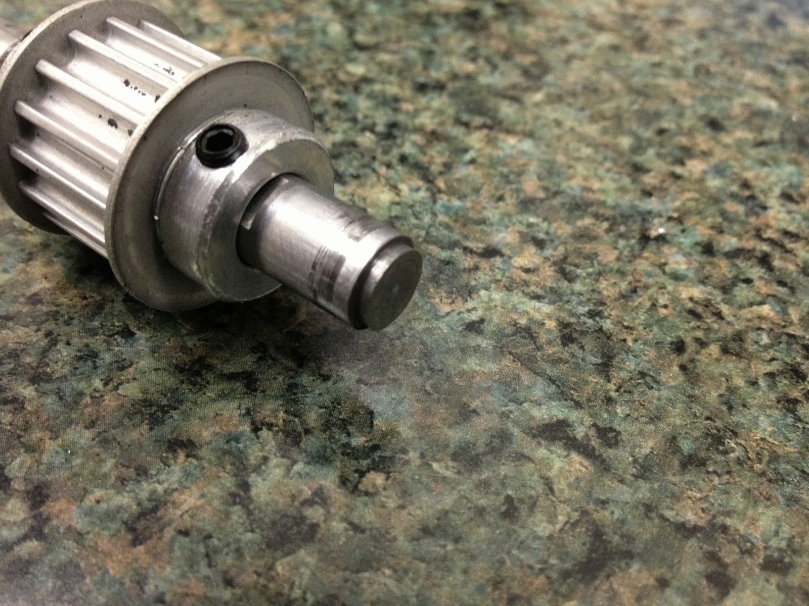
The set screws had eaten away most of the motor shaft circumference...
This is a good example of the general state of all the hardware.
So in the spring when I first attempted to quickly put the kart back together, I decided instead to take it even more apart:


Every single piece of hardware was removed. Even parts that had come as a whole (the motors) were disassembled to be cleaned and fixed. While I had the kart in a state of maximum entropy and while the weather was nice, I sanded, cleaned, primed, and painted every flat piece of aluminum. That process alone took a week.

Main front frame plates, unbent and sanded to a shiny finish.
Multirotor-assisted drying of special extra-nasty aluminum etching primer.
At this point it's been reduced to a box of parts plus some plates and 80/20 extrusions.
I rebuilt the front half of the kart first, since it had taken the most mechanical damage. Plates were mostly salvaged and the bent spindle shaft was simply refaced, sacrificing a tiny bit of length to recover a flat and perpendicular end surface. The damaged steering linkage was easy enough to replace, and I also took the opportunity to replace the steering thrust bearings and just about every piece of hardware.

A good look at the internal structure of the front half of tinyKart.
Finishing off the sandwich.
Refitting the steering column. The bowl of Rusted Flakes breakfast cereal that is the old hardware.
Half the steering linkage rebuilt, and starting to lay out the rear frame.
Maybe the second-biggest and first-most-futile task of the rebuild was fixing the EMP 6374-200 motors. (I would link to them, but they no longer exist since Leaders Hobby has dissolved and Hobby King/Turnigy has moved on to the less-satisfying SK3 line.) The first step was actually taking the motor apart, no easy task when the shaft is so mangled:


Then, I machined entirely new shafts for the motors out of 1566 carbon steel. I decided to make the shafts long enough to fit entirely through the drive pulley to the second, outrigger bearing. In the previous iteration, a second idler shaft was used on the outside of the drive pulley to complete the structural loop. The planned advantage of the longer shaft was so I could have four total set screw engagement points, two on each side of the pulley, to help torque transfer.

New shafts (left two) vs. old shaft (right).
New shafts also required new drive pulleys. I made them using the same trick of upgrading the hub of a standard Stock Drive Products HTD pulley.


The process involves carefully boring out the stock pulley to be a tight interference fit (0.002" diameter undersized) for the 10mm prop adapters that come with the motors. I luckily happened to find four more prop adapters to use for this round of pulleys. One gets pressed into each side of each pulley, with a healthy dose of Loctite 609 to aid the press fit. The result is a much beefier pulley hub that I modify even more by drilling out the 4mm set screw holes and re-tapping for 10-32 set screws.

New megabeef pulley (left) vs. wimpy old pulley (right).
Original SDP/SI pulley set screw (left) vs. prop adapter set screw (center) vs. my set screw (right).
I hoped that the combination of larger and more set screws would help improve torque transfer and stop the gradual mangling of the drive shaft that happens when you routinely run an RC airplane motor at peak torque into an inertial load. It turned out to be a moot point, which I will get to in just a moment, but first the remainder of the drive module reassembly:

The new shafts were pressed and Loctite 609'ed into the rotor cans. Probably a bad decision, in retrospect.
Anti-giant-prop-shooting-off clip added to the motor. I wish I had considered how little I need this, given the many other ways the shaft is constrained axially.
And two completed long-shaft motors, ready to re-install.
The eccentric roller tensioner is one of my favorite parts of tinyKart.
Back in place with the new pulley. The long shaft passes all the way through the outside bearing now.
I also took this opportunity to upgrade the Kelly controllers from 2x KBS36101 (36V/100A) to 2x KBS48121S (48V/120A) with high-speed firmware. Even though 100A is plenty for this kart, it was hard to achieve that number with the KBS36101 and these motors. My complete guess as to how the Kelly controllers handle current, purely based on experimental evidence, is that they perform average current control but have an additional overcurrent protection at some margin of safety higher than the maximum rated current. The addition protection will cause errors and sometimes controller shutdowns if current peaks exceed the hard-coded current limits. So, to keep the current spikes below these limits, I would have to set the maximum controlled current to about 80% (80A).

The problem is compounded by two factors: Surface permanent magnet brushless motors are about the worst-case scenario for current control, since they have very low resistance and inductance. (Okay, coreless motors are worse.) Small variations in PWM will cause large, quick changes in current. External Hall effect sensors also need to be very carefully timed or they will trip commutation in the wrong place and cause excessive current spikes. Timing the sensors was an arduous task with the KBS36101, but in order to even get to 80% of the rated current without tripping faults it was necessary to be very accurate on the timing.

The new controllers have several advantages that help keep the overcurrent faults under control. They have a bit more current overhead (120A maximum rated current vs. 100A), so if the hard-coded overcurrent fault scales proportionally, so will the controlled current limit I can achieve. But it's also the high-speed firmware version of the controller. Although it's not documented on the Kelly website, the myth is that the high speed firmware also has 32kHz PWM instead of the normal 16kHz. Higher PWM frequency means lower current ripple. If the average current is being controlled, lower current ripple could very well keep the peak currents from tripping the overcurrent limits on these low-inductance motors. Or so my thinking goes...

I left some racing stripes of bare aluminum for heat sinking the new controllers.
And after a bit of sensor timing, the left rear drive is back in action.
To further optimize the sensor timing, I drilled a set of alternate sensor board mounting holes 60edeg ahead of the existing holes:


The sensor boards have slots that allow 60edeg of adjustment already. Rotating the three power wires going to the motor gives a 120edeg shift. So that covers three alternating 60edeg segments of the possible sensor position. To get the other three slices, I had been playing games with reversing sensor and phase wires that I was never quite sure were working. By adding a new set of holes 60edeg offset from the existing holes, I am guaranteed an easy way to find the proper forwarding timing.

Pretty much the only thing from tinyKart that has survived without needing any care at all were the 12S3P A123 B456 26650 battery packs. This is how I found them after a year of sitting on a shelf unattended:

I wouldn't be surprised if that was the exact voltage they were at the day after Maker Faire NY 2012.
After fine-tuning the timing on each side and charging up the battery, it was time for the first tinyKart test drive in almost 12 months:

I think of tinyKart as a nocturnal vehicle, a little bit.
It survived it's first half-torque (60A each side) test drive with no problems, so I decided to go for 75% torque (90A each side) the next day. Then, disaster:


The brand new motor shaft that I machine fractured right at the retaining ring groove after only a few minutes of driving. I don't think the failure was entirely due to the slight increase in torque from the previous implementation of tinyKart. Such a clean break is more likely a brittle fatigue failure caused by misalignment of the inner and outer bearings, now that the single shaft passes through both. There could be other factors as well:
  • The retaining ring groove was deeper than that of the stock shaft.

  • The groove was cut with a rather high SFM. It could have work-hardened the outer layer at the bottom of the groove, which is the most important part for torque transmission.
  • The new shaft material may be harder and more brittle than the stock shaft. It didn't seem that way, but I don't have a hardness tester to confirm.
In any case, it's the first time I've seen a motor shaft fail this way. It broke during some particularly hard cornering, so it could also have to do with shock loading coming back through the belt. This was I think the only time in my life that I was hoping it was a sheared set screw or mangled flat.

All hope was not lost, however. While digging through my box of random motors, I found this:


I left most of my large motors in Massachusetts, but this one somehow made it through to the west coast with me. We bought four of these original SK6374-170's back when tinyKart was nothing more than a CAD model. The other three have been chewed up and spit out by tinyKart already. They are the predecessors to the SK3 line, and are actually 63mm in diameter with a 10mm shaft. They do not have rotor can bearings and the overall build quality is not as good as the EMP motors or the SK3s. But, they are smaller and lighter than the EMPs, they have less drag, and they're a bit more powerful (thanks to an extremely low resistance of 23mΩ line-to-line).

Not expecting it to be a permanent solution, I quickly patched the last of the SKs in to the right rear drive using the old method, an idler shaft to the outside bearing, coupled by the drive pulley itself. This leaves only the two set screw flats for torque transmission, but that's no worse than old tinyKart. Because the motor Kv ratings are different, I set the maximum speeds proportionally in the Kelly software so it would not tend to "pull" at full speed. (I don't think you'd feel it, but the motors would start to fight each other and waste power.)

I'm happy to report that even on mismatched motors and restricted to 75% torque, new tinyKart is every bit as fun as it used to be. Since this is Seattle, initial test driving would not be complete without a little bit of wet surface testing. (I know, I know, the new paint job...it won't last long anyway.) Joining me for testing on the first day of fall, just after an afternoon storm, was none other than Ryan Archer of RC airplane fame, who happened to be in town.

HI RYAN

We both took it relatively easy (read: only a little bit of sliding induced), since the kart is running on one motor that tinyKart's already eaten three of and another with a shaft that's likely to break at any moment. I've preemptively ordered three new motors from a cool site that I just found called Alien Power System. They have a lot of RC stuff that is useful on small EVs, including dual brushless ESCs with reverse. Their 63mm motors don't appear to have can bearings, but beggers can't be choosers in this post-Turnigy-Grapefruit-post-Leaders-Hobby world of 63mm motor scarcity. One thing that do mention is keyed shafts. Not sure if this is optional or included...guess I'll find out. It would be nice to solve the torque transmission problem once and for all.

But for now, tinyKart is running again. I managed to sneak it in just before the end of summer. It performs as well as ever, and is looking way better than it ever has. I'll leave off with some glamour shots of the new paint job before I totally destroy it:

Vertical storage configuraiton takes up very little space at the shop.