To start with, the
MITERS-originated
oneTesla Kickstarter is now up (and already funded!), so you can now buy your very own musical Tesla coil kit. It's pretty amazing: up to 23" sparks from a 10" coil using regular old TO-X IGBTs. And the custom MIDI interrupter can play up to two MIDI notes at the same time.
Anyway, work has been progressing on my
Dual-Resonant Solid-State Tesla Coil. I finished most of the mechanical construction in
Δt1 and
Δt2, so that mostly left soldering and testing of the driving electronics. The power electronics comprise a MOSFET H-bridge, using just one
IRFP4668 and one
APT100S20B Schottky diode per leg (with the option to add a second FET per leg for higher power). This, combined with 2000uF of electrolytic bus capacitor and the
ACNW3190 optically-isolated gate drivers form the
power board, which rests on a large heat sink directly below the coil.
I found 10ft of energy chain and bought 10ft of shielding from the last
Swapfest for making a a long run of shielded cable to go from the power board to the signal board.
The cable has 15V power, ground, and four differential gate drive signals, each in a cable shielded with signal ground. The gate drive signals are relatively low-impedance, since they drive the opto gate drive LEDs. At least a few mA is required to change their state, so they should be relatively immune to EMI, compared to logic-level signals. However, it's still
very, very necessary that the LED drive lines be tightly grouped and shielded. The outer shielding is connected to RF ground at the base of the coil, and is mostly there to protect against arc strikes on the cable assembly.
 |
| The whole thing coils up for clean storage. |
On the signal end, a
wootstick 2.0 running an STM32F103CBT6 at 72MHz provides the brains. I was finally able to get the ARM micro to run at full speed (72MHz in this case). Over a year ago when I was first venturing into sensorless motor control I ran into a
mysterious problem that was limiting me to 56MHz. Turns out it was a flash memory access latency setting, explained on page 60 out of 1096 in
The F-Ing Manual. In case anyone else is having the same problem (I doubt it, since almost everyone else uses the standard peripheral library), the missing line of code was just:
FLASH->ACR |= 2;
Anyway, having full 72MHz operation is nice because even though there isn't much processor-intensive control code, the frequencies and timing on the Tesla coil are much faster than those of the motor controller.

The switches and lights on the right side control and indicate various levels of arming the coil, including the 15V gate drive power supply, a precharge and a main relay, and the logic power supply. In order to isolate the microcontroller logic supply from the 15V gate drive supply, I use the
DCR021205 that worked so well on my
3ph v3.1 motor controllers.
Next up, my favorite part: testing gate drivers! For starters, I set up one of the timers on the STM32 to put out a ~150kHz gate drive waveform. (Two complementary pairs, 180º out of phase with each other.)
Having confirmed, that the timers and outputs were working, I hooked up the 10-foot signal cable and did my best to scope the gate signals themselves. I switched back to the analog scope, because it's just not possible to get as clean a picture of the rise/fall on the crappy digital ones (yes, I am a scope hipster). I also made myself a hack low-inductance differential probe for measuring the high side gate signal:
Since I chose all the gate resistor values with two FETs in parallel, the gate drive on a single FET was a little faster than I would have wanted. (Switching too fast causes major di/dt and dv/dt transients as the frequency content of the switching waveform starts to excite the parasitics of the gate drive and MOSFET.) So, to slow things down just a little bit, I added a bit more external resistance to the output of the gate drivers:
 |
| I swear this was the best way to do this... |
With a total external gate resistance of about 8Ω, here's the low side turn-off and high side turn-on with no voltage on the bus:
The rise/fall times are ~100ns and the deadtime is about 377ns, using 220-ohm / 1.5nF on the deadtime generating circuit. With bus voltage, the turn-on and turn-off will be longer due to the Miller plateau, but it should still be well shorter than the deadtime. At 150kHz, two 377ns deadtimes accounts for about 11% of the PWM cycle. This would be a bit long for motor controller operation, but it's okay for the Tesla coil driver, which will spend most of it's on-time operation at or near 50% anyway.
As usual, I built a Visual Basic GUI to control the whole thing:
It sets the drive frequency of the resonant circuit (for tuning to the resonant frequency), as well as the duty cycle profile over a finite number of cycles that make up a single "pulse" sent to the primary. The duty cycle for each cycle can be ramped up to some maximum value, held, and then ramped down. The GUI also sets the frequency at which the pulses are generated, which is what will ultimately be used to play MIDI notes. Here's a quick video showing the GUI tuning process with just the primary:
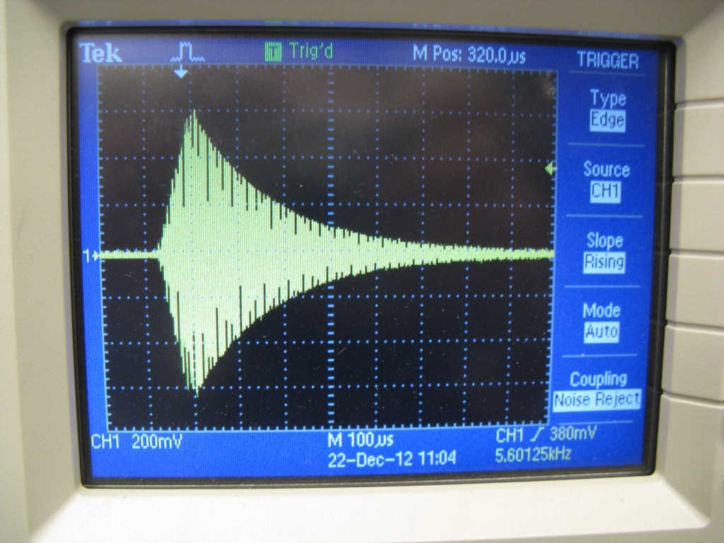
You can seem me playing with the pulse lengths, as well as the drive frequency and some other parameters. A single pulse on the primary with no secondary present looks like this:
 |
| Close-up. |
 |
| Zoomed-out. |
The current on the primary (measured using a current transformer) rings up to some maximum value quickly as the square wave voltage excites the resonant circuit. (The current itself is mostly sinusoidal.) Then, after the drive pulse ends, the energy in the primary is slowly dissipated in its resistance. With a secondary in place, energy would be coupled into the secondary coil and the primary current would look a lot different. But for testing purposes, using the primary alone at low voltage allows me to actually scope things.
The first thing to check is the primary resonant frequency. From the
design, I was targeting something in the range of 135-150kHz. Tapping the real-life primary coil at approximately 6 turns gave me a resonant frequency of 154.5kHz, measured by sweeping the drive frequency around to find the maximum ring-up. This gives a primary inductance at 6 turns of 10.6μH, since the primary capacitance was easily measured to be almost exactly 100nF. So, I'll probably have to move the tap out a little to get it in tune with the secondary. (The target frequencies for best coupling were 151kHz and 136kHz.)
Next, I wanted to use the decay time to estimate the real-life primary resistance. I could probably have just put in the peak values as initial conditions in a SPICE simulation of just the primary LRC resonant circuit. But, since I have a full
SPICE simulation of the driver already, I decided to make things more complicated by having my VB GUI export gate drive waveforms to the SPICE sim, which would simulate the entire pulse sequence. I then tweaked the resistance value until the decay envelope on the SPICE sim matched up exactly with the one on the scope:

The magic number in this case was about 90mΩ, which seems accurate given that the skin depth on my 8AWG grounding wire is probably making it act more like 14AWG wire. But anyway, I now have a more precise simulation of the exact pulse sequence, including ramping and duty cycle control. This should be useful when it comes time to ramp up the power.
Speaking of which, I discovered the USB limit for this power system. As is also the case on many of my motor controllers, USB communication and high power simply don't mix and above a certain current (40A in this case) the GUI starts to get comm. errors. Typically, the micro and all the logic circuity can continue to operate without any issues - it's just a problem with the serial communication. Since I suspected this might be an issue, the plan is to use an
XBee link to between my laptop and the logic board, the same trick I use to get data off of motor controllers while they're running. It may seem like running an RF link instead of a wired connection would be a bad idea in a Tesla coil environment, but I've been down this decision path before and the XBee always seems to win...
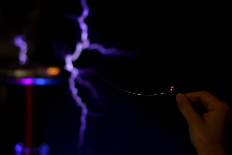
Next step: ramping up the power, tuning, and hopefully generating the first sparks!


