Showing posts with label DRSSTC. Show all posts

Saturday, November 7, 2015

DRSSTC Δt5: MIDI Streaming and Shutter Syncing

Until last week, I hadn't really touched my Tesla coil setup since I moved out to Seattle. Maybe because the next step was a whole bunch of software writing. As of Δt3, I had written a little test program that could send some basic frequency (resonant and pulse generation) and pulse shaping commands to the driver. But it was just for a fixed frequency of pulse generation and of course I really wanted to make a multi-track MIDI driver for it.

The number I had in mind was three tracks, to match the output capabilities of MIDI Scooter. While the concept was cool, the parsing/streaming implementation was flawed and the range of notes that you can play with a motor is kinda limited by the power electronics and motor RPM. So I reworked the parser and completely scrapped and rebuilt the streaming component of it. (More on that later.) Plus I did a lot of preliminary thinking on how best to play three notes using discrete pulses. As it turns out, the way that works best in most scenarios is also the easiest to code, since it uses the inherent interrupt prioritization and preemption capabilities that most microcontrollers have.


So despite my hesitation to start on the new software, it actually turned out to be a pretty simple coding task. It did require a lot of communication protocol code on both the coil driver and the GUI, to support sending commands and streaming MIDI events at the same time. But it went pretty smoothly. I don't think I've written as many lines of code before and had them mostly work on the first try. And the result is a MIDI parser/streamer that I can finally be proud of. Here it is undergoing my MIDI torture test, a song known only as "Track 1" from the SNES game Top Gear.


The note density is so high that it makes a really good test song for MIDI streaming. I only wish I had more even more tracks...


The workflow from .mid file to coil driver is actually pretty similar to MIDI scooter. First, I load and parse the MIDI, grouping events by track/channel. Then, I pick the three track/channel combinations I want to make up the notes for the coil. These get restructured into an array with absolute timestamps (still in MIDI ticks). The array is streamed wirelessly, 64 bytes at a time, to a circular buffer on the coil driver. The coil driver reports back what event index is currently playing, so the streamer can wait if the buffer is full.


On the coil driver itself, there are five timers. In order of interrupt priority:

  • The pulse timer, which controls the actual gate drive, runs in the 120-170kHz range and just cycles through a pre-calculated array of duty cycles for pulse shaping. It's always running, but it only sets duty cycles when a pulse is active. 
  • Then, there are three note timers that run at lower priority. Their rollover frequencies are the three MIDI note frequencies. When they roll over, they configure and start a new pulse and then wait for the pulse to end (including ringdown time). They're all equal priority interrupts, so they can't preempt each other. This ensures no overlap of pulses.
  • Lastly, there's the MIDI timer, which runs at the MIDI tick frequency and has the lowest interrupt priority. It checks for new MIDI events and updates the note timers accordingly. I'm actually using SysTick for this (sorry, SysTick) since I ran out of normal timers.
There are three levels of volume control involved as well. Relative channel volume is set by configuring the pulse length (how many resonant periods each pulse lasts). But since the driver was designed to be hard-switched, I'm also using duty cycle control for individual note volume. And there is a master volume that scales all the duty cycles equally. All of this is controlled through the GUI, which can send commands simultaneously while streaming notes, as shown in the video.


It's really nice to have such a high level of control over the pulse generation. For example, I also added a test mode that produces a single long pulse with gradually ramped duty cycle. This allows for making longer, quieter sparks with low power...good for testing.

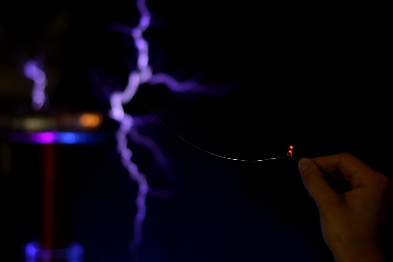
I also got to set up an experiment that I've wanted to do ever since I got my Grasshopper 3 camera. The idea is to use the global shutter and external trigger capabilities of the industrial camera to image a Tesla coil arc at a precise time. Taking it one step further, I also have my favorite Tektronix 2445 analog oscilloscope and a current transformer. I thought that it would be really cool to have the scope trace of primary current and the arc in the same image at the same time, and then to sweep the trigger point along the duration of the pulse to see how they both evolve.


The setup for this was a lot of fun.

Camera is in the foreground, taped to a tripod because I lost my damn tripod adapter.
Using a picture frame glass as a reflective surface with a black background (and a neon bunny!).
I knew I wanted to keep the scope relatively far from the arc itself, but still wanted the image of the scope trace to appear near the spark and be in focus. So, I set up a reflective surface at a 45º angle and placed the scope about the same distance to the left as the arc is behind the mirror, so they could both be in focus. When imaged straight on, they appear side by side, but the scope trace is horizontally flipped, which is why the pulse progresses from right to left.


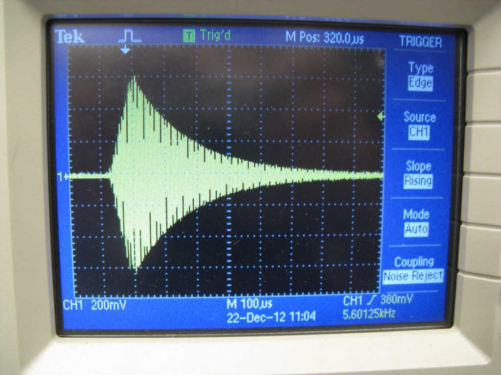
This picture is a longer exposure, so you can see the entire pulse on the scope. To make it sweep out the pulse and show the arc condition, I set the exposure to 20-50μs and had the trigger point sweep from the very start of the pulse to the end on successful pulses. So, each frame is actually a different pulse (should be clear from the arcs being differently-shaped) but the progression still shows the life cycle of the spark, including the ring-up period before the arc even forms.The pulse timer fires the trigger at the right point in the pulse through a GPIO on the microcontroller. Luckily, the trigger input on the camera is already optocoupled, so it didn't seem to have any issues with EMI.

Seeing the pulse shape and how it relates to arc length is really interesting. It might be useful for tuning to be able to see primary current waveform and arc images as different things are adjusted. No matter what, the effect is cool and I like that it can only really be done with old-school analog methods and mirrors (no smoke, yet).

Thursday, February 6, 2014

Tesla Coil Musings: Digital Polyphony

Not to be confused with Polyphony Digital, creators of the Gran Turismo series... Speaking of which, the sixth edition of the game is out (for PS3, so no need to buy a next-gen cloud-based facebook-tweeting console) and it's pretty awesome:

By the way, we're going widescreen in the main text frame from now on. Welcome to the future!

Anyway, despite GT6 and Kerbal (and stabilized camera systems), it's time to revisit one of my arch nemeses, MIDI. My last encounter was with MIDI Scooter, a rideable three-track MIDI instrument that also happens to be Pneu Scooter, which is still alive and well. MIDI Scooter's physical implementation was relatively simple: each of three notes was played on one of the motor drive's half bridges. (Three total for a three-phase permanent magnet motor controller.) The PWM frequency was the note frequency. The PWM duty cycle was controlled by the normal sensored FOC. So it could both play notes and properly drive the motor at the same time:


Knowing what I know now about how XBees work, I would say its one failing would be in attempting to stream the note data wirelessly to the controller. For the most part it worked, but it would spontaneously drop notes and had little in the way of error checking to prevent that. But that's more on the parsing, data handling, and communications stack side; the physical method of playing three notes at the same time was relatively simple and worked as expected.

For my DRSSTC, which survived a cross-country trip only to be neglected for a year, I've "solved" the streaming problem by just getting a microcontroller with enough flash memory to store an entire MIDI song's worth of data. This has the added benefit of not relying on wireless or USB in a harsh electrical environment. (Although theoretically the driver board thinks it's just controlling some LEDs...)

However, the physical implementation of multi-track MIDI note playing on a DRSSTC is a much more interesting challenge than MIDI Scooter. To begin with, it's probably important to understand how the Tesla coil generates sound in the first place. The PWM frequency for the my coil is in the 150kHz range (to nearly but not necessarily exactly match the resonant frequency of the primary and the secondary), so playing sound by varying it is out of the question. Instead, the resonance-driving high frequency PWM is turned on and off in short pulses at a lower, audible frequency. Each pulse might look something like this:


Voltage builds up and at some point there is a discharge through the air which creates the sound. The pulse is very short: on the order of 100μs PWM drive time plus some decay time that depends on a lot of things. The actual sound-producing part of the pulse is probably even shorter - only the very peak of the voltage where an arc is generated.

How that pulsed arc is transformed into a sound pressure wave is a bit beyond my ability to simulate. For the purpose of  this discussion I just assume that it creates a short square pulse of sound equal to the driving pulse length. If I had to guess, I would say the real thing is more of a triangle, somewhat narrower than the driving pulse width, and centered around the peak voltages where an arc is actually generated. The further you get from the coil, the more it gets spread out, kind-of like thunder but on a much faster time scale. But unless you take it down into a canyon or something, there will be sharp edges on the time scale of the note frequency, giving it the characteristic cracking sound.

So, most of the note will be empty space - off time. This is done by necessity - the coil operates at very high peak kVA but very low overall duty cycle so as not to overload the components. (Here, I mean audible-frequency duty cycle, not resonant frequency duty cycle.) Since the note is mostly off time, and assuming the overall duty cycle is not exceeded, it is certainly possible to play two or more notes at the same time by superimposing the pulse chains. In a hardware sense, this would be like OR-ing two signals intended to turn on the high frequency PWM driver

There is one problem though...overlapping pulses. In the worst-case, if pulses are simply OR-ed, there is the possiblity of N pulse lengths adding together, where N is the number of notes. Since it's a resonant circuit, the resulting long pulse will ring up to much higher voltages and currents than intended, leading to certain destruction. So to ensure this doesn't happen, there is a simple rule to obey: A new pulse cannot start while an earlier pulse is ongoing, or for a certain holdoff period afterward. The holdoff period is to allow for ring-down after the driving waveform has stopped.

Driving pulse followed by a possibly exaggerated no-load ring down (red).
Even though the statement of this rule is simple, there are many ways to actually implement it. Since I couldn't say for certain which way would most accurately produce the sound of three independent notes played simultaneously, I decided to do what I always do and write a VB program to solve the problem for me.

One of the ugliest and most annoying VB programs I have written.
The program just generates a WAV file of short square wave pulses at up to three note frequencies. The notes are selected by MIDI number and pulse widths can be varied independently. Holdoff is varied globally although there is no reason why this must be the case. It uses one of several methods to handle overlapping pulses:

Simple Drops: Notes are associated with up-counters that roll over after the note's period has elapsed. A pulse is generated if a note counter rolls over and no other note counter is below the pulse length plus holdoff time. Otherwise, the pulse is partially or completely skipped (dropped). It's a brute force method that I didn't expect to work well but was good for comparative testing. Unlike all the other methods, there is no priority given to lower-number notes.
Simple Drops

Counter Hold: If a pulse attempts to start during the on time or holdoff period of an earlier pulse, the counter that generates the later pulse is stopped until the end of the earlier holdoff period. After the end of the earlier holdoff period, the counter is restarted and allowed to generate its pulse. If two or more pulses try to start at exactly the same time, a fixed priority is implemented (lower number notes first).
Counter Hold


Random Phase Shift: If a pulse attempts to start during the on time or holdoff period of an earlier pulse, the counter that generates the later pulse is shifted to a random position outside of the pulse-generating range of that counter and allowed to continue running from there. (Equivalent to inserting a random delay of less than one counter period minus one pulse+holdoff time.) If two or more pulses try to start at exactly the same time, a fixed priority is implemented (lower number notes first). Inspired by packet collision avoidance methods in digital communication: If the channel is not clear, each waiting transmitter can delay a random amount to minimize the chance of getting stuck in a four-way stop sign standoff.
Random Phase Shift


ISR Priority: If a pulse attempts to start during the on time or holdoff period of an earlier pulse, the later pulse and its holdoff period are delayed until the end of the earlier holdoff period, similar to Counter Hold, but the counter that triggered the later pulse attempt is allowed to continue running. If two or more pulses try to start at exactly the same time, a fixed priority is implemented (lower number notes first). This mimics the behavior of a prioritized and unnested Interrupt Service Routine on timer compare matches. This is probably? the most common method, and certainly the method used by oneTesla interrupter for two notes (interrupter source available here).
ISR Priority


For fun and science, I also threw in two "control" methods that are not realistic to implement but are interesting for the purpose of generating comparison sounds. One simply adds pulses together. (Adds, not ORs, so 1 + 1 = 2 instead of 1 | 1 = 1.) My thinking here was that this would be the purest representation of playing two or more notes simultaneously where each note is defined as a short square wave pulse. The other is the fundamental sinusoidal case, which is useful for listening to expected beat frequencies.

And what would an algorithm test be without test cases? The test cases were chosen to best bring out the differences in the methods:

1. Same Note: Two channels attempt to play the same note. Simple enough, right??

Control: Pure Sine (.wav)
Control: 1+1=2 (.wav)
Simple Drops (.wav)
Counter Hold (.wav)
Random Phase Shift (.wav)
ISR Priority (.wav)

Loser: Simple Drops. It simply drops all the pulses.

Winner: Any of the others, really. None replicate the exact sound of 1+1=2 (twice the amplitude) but they at least play the note more loudly with two channels than with only one. ISR and Counter Hold should be identical in this test case. Random Phase Shift is interesting because it sounds different depending on what random shift is implemented on the first collision.

2. Octave: Two channels attempt to play two notes that are in the exact ratio 2:1.

Control: Pure Sine (.wav)
Control: 1+1=2 (.wav)
Simple Drops (.wav)
Counter Hold (.wav)
Random Phase Shift (.wav)
ISR Priority (.wav)

Loser: Simple Drops. It simply drops the higher frequency. Actually, it's dropping the lower frequency and every other note of the higher frequency, leaving half the higher frequency which is the lower frequency. It's effed, is what I'm saying.

Winner: This one is tough to call. I think all three other methods produce both frequencies but favor the lower of frequency note more compared to 1+1=2. Random Phase Shift again varies in sound depending on the first random shift. Once it's shifted the f and 2f pulses out of a conflicting phase, they stay where they are after that. Sometimes this sounds more like the 1+1=2 sound than the other two methods. Other times, it sounds like it's creating entirely new, even higher frequencies.

3. Half Tone: Two channels attempt to play a notes that are one half-tone apart. This should illustrate the a worst-case scenario for beat frequency effects.

Control: Pure Sine (.wav)
Control: 1+1=2 (.wav)
Simple Drops (.wav)
Counter Hold (.wav)
Random Phase Shift (.wav)
ISR Priority (.wav)

Loser: Counter Hold. It's hard to explain what exactly is going on, but it results in dropping the higher frequency note. The shorter period pulse doesn't fit between the off-time gap left by the longer period pulse, so it gets delayed every cycle. (Except at the very start, before the first beat period elapses, when you can still hear both notes.)

Winner: ISR Priority or Random Phase. Simple drops works but has obvious clicks where there are drops. ISR Priority has a more pronounced beat frequency (like Pure Sine), Random Phase disguises it with noise. At high frequencies, Random Phase sounds worse (lots of random shifts leads to a very noisy sound), but at lower frequencies it might be the winner.

4. Perfect Fifth: Two notes seven half-tones apart. Very close to 3:2 ratio. Other than the octave test, this is a worst-case scenario for a small integer relationship between notes. This is the case illustrated in the sample waveforms above.

Control: Pure Sine (.wav)
Control: 1+1=2 (.wav)
Simple Drops (.wav)
Counter Hold (.wav)
Random Phase Shift (.wav)
ISR Priority (.wav)

Loser: Simple Drops. It should be obvious from the above waveforms that this won't work. It creates all kinds of mess, dropping almost every other low frequency pulse and every third low-frequency pulse. I don't know why it sounds the way it does, but it doesn't match 1+1=2 well at all.

Winner: Counter Hold or Random Phase. Both are able to shift the 3:2 periods into non-colliding phase for the duration of the 1-second test notes. ISR Priorirty still suffers from collisions, although the distortion they create is not nearly as bad as Simple Drops.

5. Three-Note Chord:
A worst-case duty cycle test, attempting to play three relatively high frequency notes at the same time.

Control: Pure Sine (.wav)
Control: 1+1=2 (.wav)
Simple Drops (.wav)
Counter Hold (.wav)
Random Phase Shift (.wav)
ISR Priority (.wav)

Loser: Everything except ISR Priority. Simple Drops has ... a lot of drops, which sound like clicks. And everywhere where there would be a drop, Random Phase instead inserts a phase shift that, cumulatively, make it sound extremely noisy. And Counter Hold fails for similar reasons to Test Case 3, I think.

Winner: ISR Priority. It's not perfect, but for 10% overall duty cycle, it is pretty damn good.

These are certainly not all the possible test cases, and in fact each one could be tested with a wide range of note frequencies, pulse lengths, and holdoff periods, with possibly different results for different permutations. However I've now got a good feel for the strengths and weaknesses of the methods. ISR Priority seems to be the most robust (it wasn't a "Loser" in any test and was only not the Winner in the Perfect Fifth test case. It's proven, easy to implement, extensible to more than two notes, and ideal for a coil with a relatively low resonant frequency and long pulse lengths, where note-playing duty cycles are likely to be high (like mine).

However, there is something to be said for Random Phase Shift. With extremely low overall duty cycles, it might be the better choice. It can shift octaves, same notes, and 3:2 perfect fifths (and possibly other ratios) into non-colliding phases, making them more independent-sounding and disguising beat frequencies better. Its noisy sound quality at higher duty cycles outweighs these benefits overall, but it was certainly worth the exploration.

I also think that, if the real-time constraint is lifted (the pulses needn't be ORed in real time by a microcontroller using some kind of simple timer-based algorithm), it is possible to devise even more interesting methods that satisfy the holdoff constraint but produce a better match to the 1+1=2 sounds. I don't know exactly what these methods are, but there is a path of optimization to go down for sure.

For now, though, I'm eager to a) implement this on actual hardware and b) test it in conjunction with a MIDI parser on actual MIDI tracks. Not sure in which order. Stay tuned.

Thursday, January 24, 2013

DRSSTC Δt4: First (Tiny) Spark!


This post is a bit time-delayed, but a couple of weeks ago, after spending way too long designing and building my first Tesla coil, I finally put the whole system together for some low-power testing. After switching from wired USB control to XBee wireless, there seems to be no more serial port hang-up at primary currents greater than 40A. So I can control the driving frequency, pulse length, and pulse duty cycle (including ramping) from my laptop. This should prove to be very useful for tuning the coil.

The supply voltage in the video is 30V and the maximum duty cycle is 50%. Driving frequency was 155kHz, which was experimentally determined to be the primary resonant frequency. I think the pulse length was ~15 pulses. Using a long insulated stick with secondary ground connection on the end, I drew small arcs out of the breakout point just to confirm that I was in fact getting high voltage. Nothing has been tuned yet, so the spark is very small. But yay, sparks!

I think the secondary resonant frequency is significantly lower, so I will adjust both the primary coil tap (to increase inductance, add more turns or fractions of a turn) and the driving frequency to attempt to get better amplification. The goal isn't to match the frequencies exactly, but rather to get them separated by the right amount to achieve good energy transfer during one pulse sequence of N cycles. For practical purposes, I can just tweak the tap point and drive frequency to get the best arc length at a given pulse length or maximum drive current.

Once it's tuned well at low power, I will incrementally add more voltage. :P

Tuesday, January 1, 2013

DRSSTC Δt3: Driver Testing

To start with, the MITERS-originated oneTesla Kickstarter is now up (and already funded!), so you can now buy your very own musical Tesla coil kit. It's pretty amazing: up to 23" sparks from a 10" coil using regular old TO-X IGBTs. And the custom MIDI interrupter can play up to two MIDI notes at the same time.

Anyway, work has been progressing on my Dual-Resonant Solid-State Tesla Coil. I finished most of the mechanical construction in Δt1 and Δt2, so that mostly left soldering and testing of the driving electronics. The power electronics comprise a MOSFET H-bridge, using just one IRFP4668 and one APT100S20B Schottky diode per leg (with the option to add a second FET per leg for higher power). This, combined with 2000uF of electrolytic bus capacitor and the ACNW3190 optically-isolated gate drivers form the power board, which rests on a large heat sink directly below the coil.

I found 10ft of energy chain and bought 10ft of shielding from the last Swapfest for making a a long run of shielded cable to go from the power board to the signal board.


The cable has 15V power, ground, and four differential gate drive signals, each in a cable shielded with signal ground. The gate drive signals are relatively low-impedance, since they drive the opto gate drive LEDs. At least a few mA is required to change their state, so they should be relatively immune to EMI, compared to logic-level signals. However, it's still very, very necessary that the LED drive lines be tightly grouped and shielded. The outer shielding is connected to RF ground at the base of the coil, and is mostly there to protect against arc strikes on the cable assembly.

The whole thing coils up for clean storage.
On the signal end, a wootstick 2.0 running an STM32F103CBT6 at 72MHz provides the brains. I was finally able to get the ARM micro to run at full speed (72MHz in this case). Over a year ago when I was first venturing into sensorless motor control I ran into a mysterious problem that was limiting me to 56MHz. Turns out it was a flash memory access latency setting, explained on page 60 out of 1096 in The F-Ing Manual. In case anyone else is having the same problem (I doubt it, since almost everyone else uses the standard peripheral library), the missing line of code was just:

FLASH->ACR |= 2;

Anyway, having full 72MHz operation is nice because even though there isn't much processor-intensive control code, the frequencies and timing on the Tesla coil are much faster than those of the motor controller.


The switches and lights on the right side control and indicate various levels of arming the coil, including the 15V gate drive power supply, a precharge and a main relay, and the logic power supply. In order to isolate the microcontroller logic supply from the 15V gate drive supply, I use the DCR021205 that worked so well on my 3ph v3.1 motor controllers.

Next up, my favorite part: testing gate drivers! For starters, I set up one of the timers on the STM32 to put out a ~150kHz gate drive waveform. (Two complementary pairs, 180º out of phase with each other.)


Having confirmed, that the timers and outputs were working, I hooked up the 10-foot signal cable and did my best to scope the gate signals themselves. I switched back to the analog scope, because it's just not possible to get as clean a picture of the rise/fall on the crappy digital ones (yes, I am a scope hipster). I also made myself a hack low-inductance differential probe for measuring the high side gate signal:


Since I chose all the gate resistor values with two FETs in parallel, the gate drive on a single FET was a little faster than I would have wanted. (Switching too fast causes major di/dt and dv/dt transients as the frequency content of the switching waveform starts to excite the parasitics of the gate drive and MOSFET.) So, to slow things down just a little bit, I added a bit more external resistance to the output of the gate drivers:

I swear this was the best way to do this...
With a total external gate resistance of about 8Ω, here's the low side turn-off and high side turn-on with no voltage on the bus:


The rise/fall times are ~100ns and the deadtime is about 377ns, using 220-ohm / 1.5nF on the deadtime generating circuit. With bus voltage, the turn-on and turn-off will be longer due to the Miller plateau, but it should still be well shorter than the deadtime. At 150kHz, two 377ns deadtimes accounts for about 11% of the PWM cycle. This would be a bit long for motor controller operation, but it's okay for the Tesla coil driver, which will spend most of it's on-time operation at or near 50% anyway.

As usual, I built a Visual Basic GUI to control the whole thing:


It sets the drive frequency of the resonant circuit (for tuning to the resonant frequency), as well as the duty cycle profile over a finite number of cycles that make up a single "pulse" sent to the primary. The duty cycle for each cycle can be ramped up to some maximum value, held, and then ramped down. The GUI also sets the frequency at which the pulses are generated, which is what will ultimately be used to play MIDI notes. Here's a quick video showing the GUI tuning process with just the primary:


You can seem me playing with the pulse lengths, as well as the drive frequency and some other parameters. A single pulse on the primary with no secondary present looks like this:

Close-up.
Zoomed-out.
The current on the primary (measured using a current transformer) rings up to some maximum value quickly as the square wave voltage excites the resonant circuit. (The current itself is mostly sinusoidal.) Then, after the drive pulse ends, the energy in the primary is slowly dissipated in its resistance. With a secondary in place, energy would be coupled into the secondary coil and the primary current would look a lot different. But for testing purposes, using the primary alone at low voltage allows me to actually scope things.

The first thing to check is the primary resonant frequency. From the design, I was targeting something in the range of 135-150kHz. Tapping the real-life primary coil at approximately 6 turns gave me a resonant frequency of 154.5kHz, measured by sweeping the drive frequency around to find the maximum ring-up. This gives a primary inductance at 6 turns of 10.6μH, since the primary capacitance was easily measured to be almost exactly 100nF. So, I'll probably have to move the tap out a little to get it in tune with the secondary. (The target frequencies for best coupling were 151kHz and 136kHz.)

Next, I wanted to use the decay time to estimate the real-life primary resistance. I could probably have just put in the peak values as initial conditions in a SPICE simulation of just the primary LRC resonant circuit. But, since I have a full SPICE simulation of the driver already, I decided to make things more complicated by having my VB GUI export gate drive waveforms to the SPICE sim, which would simulate the entire pulse sequence. I then tweaked the resistance value until the decay envelope on the SPICE sim matched up exactly with the one on the scope:


The magic number in this case was about 90mΩ, which seems accurate given that the skin depth on my 8AWG grounding wire is probably making it act more like 14AWG wire. But anyway, I now have a more precise simulation of the exact pulse sequence, including ramping and duty cycle control. This should be useful when it comes time to ramp up the power.

Speaking of which, I discovered the USB limit for this power system. As is also the case on many of my motor controllers, USB communication and high power simply don't mix and above a certain current (40A in this case) the GUI starts to get comm. errors. Typically, the micro and all the logic circuity can continue to operate without any issues - it's just a problem with the serial communication. Since I suspected this might be an issue, the plan is to use an XBee link to between my laptop and the logic board, the same trick I use to get data off of motor controllers while they're running. It may seem like running an RF link instead of a wired connection would be a bad idea in a Tesla coil environment, but I've been down this decision path before and the XBee always seems to win...

Next step: ramping up the power, tuning, and hopefully generating the first sparks!

Saturday, November 24, 2012

DRSSTC Δt2: Primary Construction

It's been a long, long time since I first started putting together my first Tesla coil, and now I'm finally back at it. It was supposed to be a summer project, but I guess I spent too much time designing it and got distracted when the time came to actually put it together. But I'm glad I got through the secondary winding while I still had momentum. Recently, I had a crazy dream where some MITERS people were testing coils and blew up a transformer outside, so I went to hide my secondary but couldn't find it in a pile of neglected, unwinding coils. Anyway, that inspired me to get back to work.

This update is mostly about the construction of the primary circuit, consisting of an flat spiral inductor and a series capacitor that form one half of the resonant power transfer. The circuit elements are easy enough to construct: the inductor is only 6-8 turns and the capacitor is an off-the-shelf component. But they are integrated into the base of the coil, so I had some mechanical work to do (for once...).


The spiral coil is made with 8AWG grounding wire (McMaster P/N 7512K641). 25 feet of it was just barely enough to make the complete spiral on a 20in diameter circular base of 0.25in-thick polycarbonate. I marked out the spiral by unwrapping a string from an appropriately-sized spool fixed to the center of the base. Then, I drilled two small holes on either side of the spiral marker line in 90º intervals. These holes served as small zip-tie mounting points to hold the grounding wire in shape around the spiral.

Originally, I had planned to have the spiral coil on top of the polycarbonate base, as in this rendering. However,  I settled on flipping the base upside down so that the coil is below it. This makes more sense from a keep-the-high-voltage-covered perspective, although only as a supplement to the higher-priority safety plan of "don't go near it at all ever". The performance hit from decreasing the coupling would matter, but I intentionally wound the primary closer to the bottom of its PVC pipe coil form to keep the designed distance between primary and secondary coils about the same.

I calculated six turn for the primary, but added an extra turn and a half for tuning, to adjust the primary's resonant frequency. Tuning requires a movable tap of some kind, which I decided to make from scratch since jumper cable clips seemed like a bad idea.


Since the primary circuit has a total resistance of only about 70mΩ, it was important not to add a significant amount in the form of contact resistance. (Especially considering that the peak current going through the connection could be several hundred amps and the RMS current as high as maybe 50A.) I opted for a homemade screw terminal made from a small aluminum block with a copper strip bent around one side. Most of the current probably goes through the aluminum, but the copper gives it a second path that doesn't involve steel cap screws. Attached to the spiral coil, it looks like this:

Did not notice that sign when I took the picture...
I haven't measured the contact resistance, but I imagine it will add a couple milliOhms at most. To adjust the tap position for tuning, the two cap screws are loosened and the block is moved around the coil to a new location. This is the node between the inductor and the capacitor in the primary circuit, and as such is the highest-voltage point on the primary, designed to hit about 3kV in operation. I used some high-voltage noodle wire (McMaster P/N 9620T22) to connect the clamp to the capacitor; probably overkill, but it looks cool too.

Speaking of capacitor, I put together a 3S3P pack of 100nF CDE 940C30P1K-F film caps to make the primary capacitor:


It's hard to see through the double layer of heat shrink, but each capacitor has a string of four 1/4-Watt resistors of 250kΩ each, for a total of 1MΩ. These act to balance the series capacitors and also to drain the bank quickly (RC = 100ms) when it's disconnected from power. I used four resistors in series per capacitor, and three capacitors in series for the bank, so each resistor only sees about 1/12th 3kV peak (250V peak).

One other small but annoying mechanical task was making something to hold the secondary coil in place. Luckily, I found a PVC fitting of the right diameter and managed to just barely blind-tap some 4-40 holes into the side of it to hold it to the polycarbonate base:


A wire passing up through the base connects the secondary coil to ground, through one of the 80/20 columns on the side of the driver box. I'll probably add some insulation to the screw head, since it sits right below the high voltage node on the outside of the primary coil. The secondary slips right onto the PVC fitting, and it almost looks like a functional Tesla coil:


I should be able to start testing the driver next. (It's build and mostly wired.) The first task will be identifying the resonant frequency of the primary, since my driver isn't self-resonant. I will probably run some low-voltage frequency sweeps and mark out some taps on the spiral for a range of resonant frequencies around 150kHz. Once I know what the tunable range is, I can pick a spot and try it out with the secondary at increasing levels of power and re-tune as necessary. (Since it's not self-resonant, I'll have two tuning "knobs": moving the tap and adjusting the drive frequency.)

So, some day soon there will be sparks! ...and eventually music. And if you're getting impatient (understandably, since my progress has been disappointingly slow), you can soon make your own with a kit from oneTesla, started by a few HV-competent MITERS members for all your musical Tesla coil needs.