Tuesday, September 24, 2013

tinyKart Black

tinyKart is back, in black:


The last time I saw tinyKart in one piece was almost a year ago at Maker Faire NY 2012, where it was torn apart in the name of impromptu power wheels racing, including 50 or so rain-soaked endurance laps after it had already lost an entire side worth of drive and brakes in two crashes. To be fair, it was already beat up from a couple years of abuse, off-roading, snow rallying, more snow rallying, and parking garage climbing.

It was certainly not built with this in mind.
I'm actually amazed it lasted as long as it did. It was originally designed as an ultralight go-kart, one that was not a burden to move around and that took advantage of modern electric motor and battery technology instead of loading up on lead, copper, and steel like certain other go-karts. It more than fulfilled its mission in that it was not only as light and portable as envisioned, but also more powerful and fun to drive than we thought it might be given the weight compromises.

If anything, it's weight-saving tradeoffs became secret advantages: chassis flex from the aluminum extrusion frame helps keep all four wheels in contact with the ground; narrow tires match the weight and power to give it a nice, predictable traction envelope. The result was that, somewhat to my surprise, I actually wound up liking the way it drove a lot more than Cap Kart, which was more of a no-nonsense, high-power, infinite traction machine. And unlike Cap Kart, we could take it out whenever we wanted since it serves as its own hand truck.

So I was sad to see it broken and in pieces for so long. Though, it did make it easier to package for shipping to Seattle when I moved out in this direction:

Picture frame box? You mean go-kart box?
Anyway, it's been a long, slow process putting it back together. Mostly because every time I would strip down another layer, I would discover another problem. It essentially came to breaking down the entire kart and rebuilding it from scratch, replacing parts as needed. And since I would have it down to atomic pieces anyway, why not paint it? Except I suck at painting things so pretty much the only color I could pull off would be flat black. Turns out to be a pretty good color anyway.

But first, an assessment of the post-Maker Faire 2012 (and indeed two year sum total) damage that it stared with:
Bent front frame plates, bent front-right spindle shaft, necessitating brake caliper removal.
Bent front frame on the other side. We were originally thinking of leaving these corners off...glad we didn't.
Bent spindle shaft and steering linkage.


As I stripped parts off, I found more and more damage:

Drive pulleys essentially destroyed. One belt had changed itself from a toothed belt to a flat belt with help from a corner of the motor mount.
The set screws had eaten away most of the motor shaft circumference...
This is a good example of the general state of all the hardware.
So in the spring when I first attempted to quickly put the kart back together, I decided instead to take it even more apart:


Every single piece of hardware was removed. Even parts that had come as a whole (the motors) were disassembled to be cleaned and fixed. While I had the kart in a state of maximum entropy and while the weather was nice, I sanded, cleaned, primed, and painted every flat piece of aluminum. That process alone took a week.

Main front frame plates, unbent and sanded to a shiny finish.
Multirotor-assisted drying of special extra-nasty aluminum etching primer.
At this point it's been reduced to a box of parts plus some plates and 80/20 extrusions.
I rebuilt the front half of the kart first, since it had taken the most mechanical damage. Plates were mostly salvaged and the bent spindle shaft was simply refaced, sacrificing a tiny bit of length to recover a flat and perpendicular end surface. The damaged steering linkage was easy enough to replace, and I also took the opportunity to replace the steering thrust bearings and just about every piece of hardware.

A good look at the internal structure of the front half of tinyKart.
Finishing off the sandwich.
Refitting the steering column. The bowl of Rusted Flakes breakfast cereal that is the old hardware.
Half the steering linkage rebuilt, and starting to lay out the rear frame.
Maybe the second-biggest and first-most-futile task of the rebuild was fixing the EMP 6374-200 motors. (I would link to them, but they no longer exist since Leaders Hobby has dissolved and Hobby King/Turnigy has moved on to the less-satisfying SK3 line.) The first step was actually taking the motor apart, no easy task when the shaft is so mangled:


Then, I machined entirely new shafts for the motors out of 1566 carbon steel. I decided to make the shafts long enough to fit entirely through the drive pulley to the second, outrigger bearing. In the previous iteration, a second idler shaft was used on the outside of the drive pulley to complete the structural loop. The planned advantage of the longer shaft was so I could have four total set screw engagement points, two on each side of the pulley, to help torque transfer.

New shafts (left two) vs. old shaft (right).
New shafts also required new drive pulleys. I made them using the same trick of upgrading the hub of a standard Stock Drive Products HTD pulley.


The process involves carefully boring out the stock pulley to be a tight interference fit (0.002" diameter undersized) for the 10mm prop adapters that come with the motors. I luckily happened to find four more prop adapters to use for this round of pulleys. One gets pressed into each side of each pulley, with a healthy dose of Loctite 609 to aid the press fit. The result is a much beefier pulley hub that I modify even more by drilling out the 4mm set screw holes and re-tapping for 10-32 set screws.

New megabeef pulley (left) vs. wimpy old pulley (right).
Original SDP/SI pulley set screw (left) vs. prop adapter set screw (center) vs. my set screw (right).
I hoped that the combination of larger and more set screws would help improve torque transfer and stop the gradual mangling of the drive shaft that happens when you routinely run an RC airplane motor at peak torque into an inertial load. It turned out to be a moot point, which I will get to in just a moment, but first the remainder of the drive module reassembly:

The new shafts were pressed and Loctite 609'ed into the rotor cans. Probably a bad decision, in retrospect.
Anti-giant-prop-shooting-off clip added to the motor. I wish I had considered how little I need this, given the many other ways the shaft is constrained axially.
And two completed long-shaft motors, ready to re-install.
The eccentric roller tensioner is one of my favorite parts of tinyKart.
Back in place with the new pulley. The long shaft passes all the way through the outside bearing now.
I also took this opportunity to upgrade the Kelly controllers from 2x KBS36101 (36V/100A) to 2x KBS48121S (48V/120A) with high-speed firmware. Even though 100A is plenty for this kart, it was hard to achieve that number with the KBS36101 and these motors. My complete guess as to how the Kelly controllers handle current, purely based on experimental evidence, is that they perform average current control but have an additional overcurrent protection at some margin of safety higher than the maximum rated current. The addition protection will cause errors and sometimes controller shutdowns if current peaks exceed the hard-coded current limits. So, to keep the current spikes below these limits, I would have to set the maximum controlled current to about 80% (80A).

The problem is compounded by two factors: Surface permanent magnet brushless motors are about the worst-case scenario for current control, since they have very low resistance and inductance. (Okay, coreless motors are worse.) Small variations in PWM will cause large, quick changes in current. External Hall effect sensors also need to be very carefully timed or they will trip commutation in the wrong place and cause excessive current spikes. Timing the sensors was an arduous task with the KBS36101, but in order to even get to 80% of the rated current without tripping faults it was necessary to be very accurate on the timing.

The new controllers have several advantages that help keep the overcurrent faults under control. They have a bit more current overhead (120A maximum rated current vs. 100A), so if the hard-coded overcurrent fault scales proportionally, so will the controlled current limit I can achieve. But it's also the high-speed firmware version of the controller. Although it's not documented on the Kelly website, the myth is that the high speed firmware also has 32kHz PWM instead of the normal 16kHz. Higher PWM frequency means lower current ripple. If the average current is being controlled, lower current ripple could very well keep the peak currents from tripping the overcurrent limits on these low-inductance motors. Or so my thinking goes...

I left some racing stripes of bare aluminum for heat sinking the new controllers.
And after a bit of sensor timing, the left rear drive is back in action.
To further optimize the sensor timing, I drilled a set of alternate sensor board mounting holes 60edeg ahead of the existing holes:


The sensor boards have slots that allow 60edeg of adjustment already. Rotating the three power wires going to the motor gives a 120edeg shift. So that covers three alternating 60edeg segments of the possible sensor position. To get the other three slices, I had been playing games with reversing sensor and phase wires that I was never quite sure were working. By adding a new set of holes 60edeg offset from the existing holes, I am guaranteed an easy way to find the proper forwarding timing.

Pretty much the only thing from tinyKart that has survived without needing any care at all were the 12S3P A123 B456 26650 battery packs. This is how I found them after a year of sitting on a shelf unattended:

I wouldn't be surprised if that was the exact voltage they were at the day after Maker Faire NY 2012.
After fine-tuning the timing on each side and charging up the battery, it was time for the first tinyKart test drive in almost 12 months:

I think of tinyKart as a nocturnal vehicle, a little bit.
It survived it's first half-torque (60A each side) test drive with no problems, so I decided to go for 75% torque (90A each side) the next day. Then, disaster:

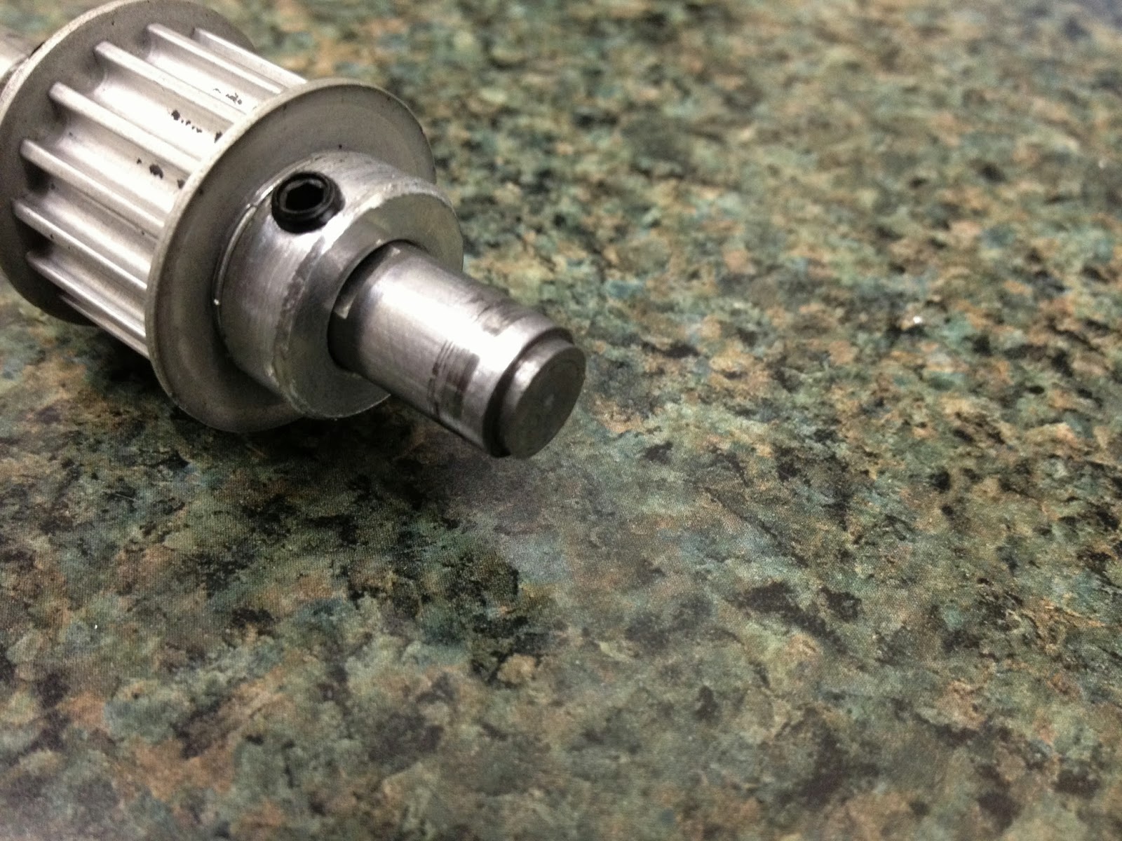

The brand new motor shaft that I machine fractured right at the retaining ring groove after only a few minutes of driving. I don't think the failure was entirely due to the slight increase in torque from the previous implementation of tinyKart. Such a clean break is more likely a brittle fatigue failure caused by misalignment of the inner and outer bearings, now that the single shaft passes through both. There could be other factors as well:
  • The retaining ring groove was deeper than that of the stock shaft.

  • The groove was cut with a rather high SFM. It could have work-hardened the outer layer at the bottom of the groove, which is the most important part for torque transmission.
  • The new shaft material may be harder and more brittle than the stock shaft. It didn't seem that way, but I don't have a hardness tester to confirm.
In any case, it's the first time I've seen a motor shaft fail this way. It broke during some particularly hard cornering, so it could also have to do with shock loading coming back through the belt. This was I think the only time in my life that I was hoping it was a sheared set screw or mangled flat.

All hope was not lost, however. While digging through my box of random motors, I found this:


I left most of my large motors in Massachusetts, but this one somehow made it through to the west coast with me. We bought four of these original SK6374-170's back when tinyKart was nothing more than a CAD model. The other three have been chewed up and spit out by tinyKart already. They are the predecessors to the SK3 line, and are actually 63mm in diameter with a 10mm shaft. They do not have rotor can bearings and the overall build quality is not as good as the EMP motors or the SK3s. But, they are smaller and lighter than the EMPs, they have less drag, and they're a bit more powerful (thanks to an extremely low resistance of 23mΩ line-to-line).

Not expecting it to be a permanent solution, I quickly patched the last of the SKs in to the right rear drive using the old method, an idler shaft to the outside bearing, coupled by the drive pulley itself. This leaves only the two set screw flats for torque transmission, but that's no worse than old tinyKart. Because the motor Kv ratings are different, I set the maximum speeds proportionally in the Kelly software so it would not tend to "pull" at full speed. (I don't think you'd feel it, but the motors would start to fight each other and waste power.)

I'm happy to report that even on mismatched motors and restricted to 75% torque, new tinyKart is every bit as fun as it used to be. Since this is Seattle, initial test driving would not be complete without a little bit of wet surface testing. (I know, I know, the new paint job...it won't last long anyway.) Joining me for testing on the first day of fall, just after an afternoon storm, was none other than Ryan Archer of RC airplane fame, who happened to be in town.

HI RYAN

We both took it relatively easy (read: only a little bit of sliding induced), since the kart is running on one motor that tinyKart's already eaten three of and another with a shaft that's likely to break at any moment. I've preemptively ordered three new motors from a cool site that I just found called Alien Power System. They have a lot of RC stuff that is useful on small EVs, including dual brushless ESCs with reverse. Their 63mm motors don't appear to have can bearings, but beggers can't be choosers in this post-Turnigy-Grapefruit-post-Leaders-Hobby world of 63mm motor scarcity. One thing that do mention is keyed shafts. Not sure if this is optional or included...guess I'll find out. It would be nice to solve the torque transmission problem once and for all.

But for now, tinyKart is running again. I managed to sneak it in just before the end of summer. It performs as well as ever, and is looking way better than it ever has. I'll leave off with some glamour shots of the new paint job before I totally destroy it:

Vertical storage configuraiton takes up very little space at the shop.


Thursday, August 29, 2013

Yes, yes I do need more flying things.

My fleet of flying things has grown quite a bit over the last few months, and I'm not just referring to Kerbal ships. First off, a little pocket quad!


This is the HobbyKing Pocket Quad, a tiny < 30g single-PCB quadrotor that comes ready to bind to a Spektrum transmitter. (Well, first you had to glue the motors in place with hot glue, and then discover that the entire craft vibrates like crazy unless you glue them much lower in the booms than the product images indicate.) The newer model (v1.1) comes with plastic motor mounts, which is nice. And it really is a pocket quad, no joking:

Well, maybe time for cargo pants...
Having built a single-PCB miniature quadrotor, I know how tough they are to make stable compared to their big counterparts. The propeller slew rates and sensor bandwidth required to keep up with the fast mechanical time constant of a miniature/micro quad are hard to achieve even in a completely rigid system. Throw in nasty mechanical resonance excited by high RPM motors and you get a controls nightmare.

This quad is so small that I feel like quantum mechanics might be coming in to play as well. The heart of the control system is a MultiWii-compatible sensor suite (MPU-6050 flavor) and ATmega32u4. So, you can tune it using the MultiWii GUI which is well known and easy to use. It has directly-controlled brushed motors, so there's no problem of slow brushless ESCs to deal with.

And, oh yes, important point: it does fly.
Out of the box (actually, it came in a static bag), it's not quite as graceful as a Walkera Ladybird. But that could be mostly due to the less-than-ideal motor mounting in the v1.0 frame that I got. Or it could be that it requires a bit of MultiWii fine-tuning. Since I recall one of the very first almost unbelievably stable nano quadrotors was based on MultiWii, I'm not surprised this one is also pretty easy to fly.

Speaking of MultiWii, I still have one laying around that I used to write some dirt-simple attitude estimation code. The ultimate goal is to create a flight controller out of less than 500 lines of code .(It's Arduino C code, so the 500 line limit assumes some libraries to take care of low-level things like I2C reading.) The point isn't to improve on the MultiWii control code, just to strip down quadrotor flight control to its absolute simplest functional form. Something to bridge the gap between control theory and actual, readable C code that people can understand without digging through abstracted libraries.

Anyway, such a project, if it does pan out, will require a new airframe. Actually, that's a complete lie and I just wanted a new airframe.


This is a size I have yet to play with - an F330. (Thanks for the frame, DGonz.) It's a good bit smaller than the Talon, which is probably a good thing for testing a completely custom flight controller. I have a hunch that it's actually a really good size for a GoPro-carrying quad...if you can work out the vibration isolation problem that plagues small GoPro quads. Anyway, even if it proves useless for GoProing, it will make a nice test frame that is essentially free.

The motors are Turnigy Air L2210C-1200's, also from HobbyKing. On one hand, they are well-built, have extremely low cogging, and good Kv/resistance combination for their size. On the other hand, they suffer from the axial play issue that makes small outrunners awful. (The rotor can is not axially preloaded, so it loosens slightly and then makes a ratcheting noise as it moves due to magnetic forces.) 

And on the third hand that you didn't even know you have, the prop adapters are terrible. They are extremely tall, which makes them almost useless for quads for the same reason that gluing the motors in the Pocket Quad as they are pictured in the product image is awful. Having the props so far away from the boom is a recipe for vibration, since any imbalance now has a huge moment arm for twisting the boom. I have attempted to modify them as much as possible to get the props down closer to the booms, but it might be hopeless. Maybe time to try out some different options.

One thing that was very helpful on this build was the 4-way XT60 to 3.5mm bullet splitter.
For ESCs, I used the same FFv1.2s's that have served me well on the Talon for quite a while now. They're a little big for this size frame, but I managed to fit them in sideways in a way that doesn't seem too inefficient.

And some lighting.
And until I create my mythical sub-500 line flight controller, it'll use a KK2 running the latest firmware (v1.6), which is pretty solid. Blah blah Stability blah GPS blah...it's less than $30, it has an LCD on board for tuning, it reliably arms and disarms on command, and I thoroughly understand the control code at work inside of it (because I can go read it myself), which makes me actually trust it. Maybe to people who treat every flight controller as a magic black box the perception of value and reliability is very different...

Oh, I forgot one other important reason why I wanted an F330: It fits in a backpack. This had only hypothetical benefit to me until the day after I completed this quad and went on my very first West-coast hiking trip with high-mountain-and-high-voltage-loving Tyler, as well as some other timezone-shifted MIT people. We went on a "tame" (Tyler's definition, not mine) hike up to Pratt Lake. I asked if there would be some flat, open area around the lake from which to take off and land.

"Yes."
I did find one rock with a flat enough top to take off and land from on the 30º rock slope. The picture above is actually from the quad's GoPro just before returning to my little landing pad rock. Unfortunately the video itself is not very pretty at this point due to the wonderful world of CMOS and vibrations. But the stills were worth the quick test flight.

A view of the lake from about 75-100ft up. Yes, I could have simple climbed back up the rock slope to get virtually the same picture. But dammit this is the future and there must be flying robots involved.
Spying on the rest of wilderness-MITERS (label stolen from Amy) from behind a tree.
So the next step for the F330 project is to travel down the wonderful road of vibration minimization and isolation. Precision propeller balancing, custom prop adapter turning, motor replacement, motor balancing, and silicone/memory foam padding are all stops I might visit along this path. Finding the magic combination to mechanically filter the prop vibrations (~50-100Hz in this case) is an annoying but straightforward task. In addition to making the video more tolerable, it will reduce gyro noise at that frequency, which should simplify the control task a lot.

There's one last new addition to the fleet. This one is also small and from HobbyKing, but it only has one rotor (gasp).

Well, two rotors actually.
It's a Turnigy FBL100, HobbyKing's counterpart to the Blade mCP X. These are nano-scale flybarless helicopters, which are such a giant leap from the counter-rotating-blade mall toys from not that long ago that I had to have one. I've never flown a collective-pitch RC helicopter before, so I figured this would be a good way to start learning. The trick is is that the blade pitch can be negative, meaning you can fly inverted and do other crazy RC helicopter things. And by "you" I mean not me. 

But it was easy enough out of the box for me to simply hover. It has active 3-axis electronic stabilization (in lieu of a flybar) using three very tiny and very cool linear servos controlling a CCPM swash plate, as well as a feedback-controlled tail rotor. That used to be a lot of controls to fit in a tiny package, but not anymore, this is the future. I do wish I could tweak the controls and the pitch/throttle curves. (You can do the latter, if you buy the transmitter module for use with your own radio instead of using the stock included transmitter.) But even with just stock setup it's fun.

And then you add a strobe light and it becomes 10x more fun (and ~3x more difficult to fly):

Monday, June 17, 2013

KSP: Interplanetary Transport Ships I & II

Kerbal Space Program is my new favorite game, at least until Gran Turismo 6 comes out in the Fall. If you haven't tried it out yet, you should do so. (But only if you have many hours to spare while you discover just how hard it is to even get into orbit.)

Having gotten the hang of landing on Kerbin's moon (Mun) and return, I decided to move on to bigger and better things and build an interplanetary ship back in version 0.18 of the game. (It's still in development, so v1.0 is yet to be released.) The actual propulsive requirement for an interplanetary ship is not unreasonable, given the available parts, and Kerbals don't really care about other resources like water, food, and time. (Radiation shielding? Not important. They're already green.)

I speculated that the first Interplanetary Transport Ship could, with a Kerbin Orbit Rendezvous flight plan, make a trip to Duna, the Kerbol equivalent of Mars, and back. The trick is to dock two ships in low Kerbin orbit, transfer fuel to one, and then use whatever fuel is remaining in the second ship to boost two-ship combo towards deep space, into a highly-elliptical orbit of Kerbin.


The second ship then turns around and returns to Kerbin (using almost no fuel) while the fully-fueled ship continues to burn past Kerbin escape velocity and onto an interplanetary transfer orbit. It's very efficient, assuming you've timed your transfer correctly, leaving you with a nearly-full ship on the way to another planet, in this case Duna:

My method for timing the transfer was to print and cut out a paper triangle and wait for the planets to line up on the edges...
Another necessary technique for interplanetary travel is aerobraking: using the atmosphere of a planet (or moon) to slow you down, instead of rockets and fuel. It's a pretty complicated aerodynamics problem to figure out how deep into the atmosphere to go to reduce your speed by a desired amount. One option is to take multiple shallow passes, reducing your speed little by little, orbit by orbit. But what if you are attempting aerocapture: braking enough to be captured from a hyperbolic escape trajectory into a planet's orbit. There, you get only one chance. Too much and you are crashing to the surface. Too little and you are skipping back off into space.

Arriving at Duna on a hyperbolic flyby trajectory...set up for an aerocapture.
It turns out that there's some relatively simple calculating that one can do using only parameters readily available in KSP. I found this in a paper and presentation on aerobraking from an academic conference. There's still a lot of maths involved, but I arranged the important equations into a simple spreadsheet. Enter the current orbital data (speed and altitude) and the aerobraking altitude at periapsis (closest approach) for a particular body, and it will calculate the exit orbit. But does it work?

AAAAAAAAAAAHHHHHHHHHHHHH!
Aaaand capture.
After trying it out a few times on Duna and Kerbin, I can say for sure that that formula works. If you use the pre-aerobraking periapsis, the output orbit will be somewhat less energetic than predicted (lower apoapsis), but I think this is mostly due to the slight reduction in periapsis that occurs at the front end of the aerobraking pass. If you use the true periapsis from the middle of the pass, the result should be even more accurate. Of course, that's not useful for mission planning, so a more practical tip is just to leave some margin for error by targeting a higher exit orbit than you really want. 

The simple formula works for hyperbolic escape trajectories as well (possibly even better than for elliptical orbits, since the predicted periapsis is not going to change much when you enter the atmosphere on such an energetic, straight-line path). So, for aerocapture it's a very useful tool. Something from real-world rocket science is actually applicable to KSP! That was probably the most exciting KSP discovery for me yet. And it allowed me to get to low Duna orbit with essentially a full tank remaining.

Getting down to the surface of Duna is, without a doubt, the hard part.

As the Mars analog in KSP, Duna presents the same challenges to its potential landers as the real thing. The atmosphere is thick enough to permit the use of aerobraking and parachutes, but too thin to land on chutes alone, especially with the mass of a fully-fueled interplanetary ship coming down. I forgot that I had put four large parachutes on the ship for exactly the purpose of slowing it down, so I opted instead for a terrifying completely-powered descent on rockets. (Same as landing on Mun, but with much more gravity.) It was so terrifying, in fact, that I really didn't have time for screenshots on the way down. But here's the massive craft, landed safely on a slight incline:


The deorbit and powered descent took, in total, 2,059m/s of delta-v (the most convenient metric of propulsive effort, since it is independent of the mass of a craft). Though it didn't exist at the time, the official delta-v map of the Kerbol System suggest an ideal Duna landing from low orbit can be done on about 1,380m/s of delta-v, which I believe, since my landing was far from ideal. The ascent was much better, clocking in at 1,532m/s, plus an additional 110m/s for inclination adjustment to get in plane with Kebin's orbit for the trip home.

All tallied up, the round-trip mission from Kerbin orbit to Duna surface and back racked up 5,576m/s of delta-v from the primary ship and an additional 928m/s boost from the Kerbin Orbit Rendezvous ship. Had I used the ship as originally planned (staging all four side tanks and LV-N engines at the same time), the available delta-v would have been 5,685m/s, still enough to make the trip, but just barely. Mid-trip, I decided on the more efficient method of dropping two tanks at a time, reducing the weight of the remaining ship and extending the range a bit. But that gave me an idea for an even more capable ship, which I have now built...

Interplanetary Transport Ship 2

You'll also note the change in aspect ratio, indicating I can finally run KSP on full 1920x1080 on my new laptop!
This ship is built in v0.20 of the game, which has several new additions such as solar panels, new engines, and reentry effects (visual only, for now).

It's almost the same ship, and the launch booster is in fact identical, but there are subtle differences to the transport ship (what you see above) that make it much more capable than the last. The main difference is that two of the LV-N nuclear engines have been swapped out for LV-T30 liquid fuel engines. (Both engines use liquid fuel...the LV-N is much more efficient but also has much lower thrust.) This opens up the possibility of high-thrust ascent. The ship can even, just barely, lift off from Kerbin. (It would not be able to reach orbit, I don't think.) More interestingly, it has a comfortable thrust margin for lifting off from Laythe, the only other inhabitable body in the Kerbol system. Yes, this ship is designed for a round-trip mission to Laythe, just as the last was designed for a mission to Duna.

A Laythe mission would require very careful planning, and mostly likely both Kerbin and Laythe Orbit Rendezvous for refueling. (A total of three ships? Maybe even more.) And a completely powered descent to Laythe is pretty much out of the question - it will have to be parachute-aided. This is difficult since there isn't much land to target on the watery Kerbin-sized moon. However there's no fuel to waste tweaking the entry; almost an entire full tank of fuel is required for Laythe ascent, I think. It will be much, much harder than the Duna mission, but I think a relay team of these ships is capable of pulling it off, now that the problem of Laythe ascent stage has been solved by swapping two engines for ones with more thrust.

The beauty of the swap is that it doesn't hurt the efficiency of interplanetary burns at all. Two LV-Ns are just as fuel-efficient as four. The burns are just twice as long. Furthermore, the shorter LV-T30 engines leave enough room for some small fuel tanks. So although the ship is 3.9% heavier at launch than its predecessor, it carries 6.3% more fuel. A larger ratio of fuel to non-fuel means more delta-v. If used entirely for interplanetary burns (no atmospheric burns), and if the two empty tanks are dropped when they run dry, the available delta-v from the LV-Ns is 7,346m/s! Looking at the master map again, that's enough to go almost anywhere...


The mission outline might be something like this:
  1. Two ITS2 ships dock in low Kerbin orbit. One is maxed out on fuel. The other is used to boost the first into a Jool transfer orbit, or as close as possible to one. (The primary ship can finish off the transfer burn.) The boost ship returns to Kerbin.
  2. The first ship to Jool aerobrakes into an orbit that intersects that of Laythe. (Basically recreating this scene from 2010.) It then aerocaptures into Laythe orbit. All using minimal fuel.
  3. Repeat steps 1 and 2. A second ship is now in Laythe orbit. The two execute a first Laythe orbit rendezvous. The lander ship (either of the two) is refueled.
  4. Lander ship decouples and deorbits, landing on Laythe with the aid of parachutes. This is the trickiest operation, since there is very little land mass to aim for and almost no fuel can be wasted for tweaking the descent. Only a small burn at the end to slow the craft to landing speeds should be necessary.
  5. Lander ascends, using most of its fuel to get into Laythe orbit and re-rendezvous with the orbiting ship.
  6. The two ships return to Kerbin together, possibly first diving towards Jool to build up speed for a transfer burn? If this isn't possible, all crew and fuel would have to be transferred to one ship for the return. (Each ship is partially-crewed at the start for this option?)
It's a bit sketchy, but none of it seems impossible with the new ship. As long as it can get off of Laythe, the rest comes down to refueling waypoints. Before I take on the challenge, though, a few shakedown tests of the new ship:
A quick trip to Mun...
And my first landing on Minimus.
Did you know that it's possible to orbit a Kerbal on Minimus using jetpack propulsion? Deorbit did not go as well...
A test mission to the Joolian system, into Laythe orbit, and back is also in order to get a feel for transfer burn delta-v, aerobraking heights, and the best return path. (Dive towards Jool or direct from Lathe? My hunch is diving is much better.) I may also attempt to make some accessories to take. (Rover? Habitation module? Unmanned probes for testing Laythe descent trajectories?) For now, though, the primary ship looks solid and ready. Here are some specs:

Interplanetary Transport Ship II (ITS2)
Crew: 3
Empty Mass: 25.93t
Fuel Capacity: 34.00t
Full Mass: 59.93t

Engines: 2x LV-N, 2x LV-T30, 1x Rockomax "Poodle"

Maximum Thrust: 770kN (78.52t) 
Maximum Full Acceleration: 1.310g
Maximum Empty Acceleration: 3.028g

Range (Lander Configuration): ~5,340m/s
Range (Interplanetary Configuration): ~7,350m/s

Wednesday, April 24, 2013

NAB 2013: Where are the gyros? / New video editing software.

A couple weeks ago I was at the NAB Show with Freefly for the MōVI launch, the first product I've helped work on at the new job. That meant spending a lot of time doing the chicken head dance and explaining to people that there aren't actually spinning flywheel gyros on things anymore...


It's a camera gimbal, similar to what would be mounted to a helicopter or multirotor, that you can also carry around in your hands while it stabilizes the camera. (If you read this blog, I'm sure you know all about control systems and active stabilization so this probably doesn't amaze you as much as it still amazes the non-technical public...)

Since I spent nine hours a day at the booth talking to people about gyros (Wait, is this Maker Faire all over again?), I didn't get as much time as I would have liked to wander around this expansive tradeshow, which covered three whole buildings. (It's about 10x the size of the EVER Monaco Expo / car show I've been to a couple times.) There were definitely a lot of camera-carrying multirotors this year.

Here is just one of many....
I was mostly impressed by how it folded up.
There was also a giant two-story indoor flying tube where DJI showed off some of their products. And several outdoor booths with all manner of flying cameras ranging from GoPros up to big-budget cinema cameras like the RED Epic. Speaking of RED, they had a clean room installed on the show floor where they were doing live sensor upgrades to their new 6K / 100fps sensor. (So to watch the video it produces, you need nine HD screens in a 3x3 grid and it has to play in 4x slow motion...)

Most of the camera stuff at NAB is way outside my budget, but one thing that excited me was the Blackmagic Pocket Cinema Camera, which was also just announced at the show. It shoots raw or high bit-rate compressed 1080p video onto normal (but expensive/fast) SD cards. If I were planning to upgrade from my Panasonic HD camcorder in the near future, the $995 price is not that bad. The only real problem for me is that it weighs 355g, (maybe less than 500g with a small lens?), so I would be instantly tempted to put it on a multirotor, and then I would be at risk of crashing it all the time. I doubt it's as durable as my GoPro...

I think of all the NAB Show things I saw later read about on the internet, the one that caught my attention most was new, free-ish video editing software called Lightworks, by EditShare. I was pretty disappointed that the new Windows 7 edition of Windows Live Movie Maker is a stripped-down piece of crap, even compared to the at least somewhat functional WMM from the Windows XP era. (The old WMM had an active user community with lots of third-party add-ons for people who wanted to use it as an actual tool.) So a new piece of editing software that doesn't cost hundreds or thousands of dollars was definitely something I wanted to try out. And it looks like a very nice tool.

Maybe I was attracted to Lightworks because the desktop layout is almost indistinguishable from that of a CAD program:


Which of these is the video editing software and which makes 3D models?
Despite being a relatively new program (I'm using the Windows beta version), the interface feels very smartly developed and intuitive. Combined with a set of quick-start video tutorials, I didn't have to spend much time at all to learn how to do simple things like make clips, arrange a timeline, trim ins and outs, work with audio tracks, and add simple effects like fades and dissolves. The options for moving a cut are particularly nice: you can make clips on either side of the cut longer or shorter independently or have one get longer and the other get shorter at the same time (to keep sync). Maybe this is a pretty standard feature in professional editing software, but it's my first time using it and I can't imagine how to ever work without it now.

The only part of the workflow that was not quick and easy was exporting video. Importing from various formats works great, but exporting to something other than a hardcore (and huge) editing format was a challenge for me. H.264 support is through Quicktime, maybe? The new beta version may support native H.264 without Quicktime but I failed to make that work. So in addition to buying the Pro version of the software, you have to also have Quicktime Pro to create H.264 files? And then after all that the H.264 output had no audio (a known bug). Luckily, you can export the audio track as a .WAV, so after fooling around for a few hours to get the H.264 export to work, I still had to use my trusty all-purpose MEncoder shell program to reattach the audio.

I'm sure the export quirks will be worked out in newer versions of Lightworks, though. If the software stays the same price ($60 for the Pro version with full codec support, including H.264?), then it's an amazing deal for a real editing tool.

To test out the software, I've finally gotten around to collecting up all my random GoPro clips from around MIT, flying with my Talon quad. No fancy stabilized 3-axis gimbal for me (well, no gimbal at all...just taped to the bottom of the quad), so get ready for a rough ride: