Showing posts with label pneu. Show all posts

Tuesday, October 2, 2012

Maker Faire NY 2012

I spent the last weekend at a DIY 3D printer convention Maker Faire NY with the MITERS crew showing off some projects from the past year, as well as some older ones. Last year was my first time attending a full Maker Faire, although I've done the Cambridge Mini Maker Faire several times. Armed with a better understanding of exactly how many little kids with inattentive parents were going to try to touch, climb on, and ride the sharp and dangerous projects, I came better prepared this year:


Yes, tinyKart made it down again, this time with a new license plate. Getting it down was a little trickier than last year, since we had to bring nine people plus all the projects in one minivan and one Jeep. That meant going a step further than the two-piece configuration that made it down last year. This year, tinyKart was packed entirely flat and stuck in the back of the minivan along with all of my other small projects:

And I just sat in the seat the whole way down.
I almost didn't bring tinyKart this year, but I'm sort-of glad I did because it was able to finally get a tiny bit of "track" time on the Power Racing Series track at Maker Faire. The Power Racing Series is a relatively new racing league for modified Power Wheels-style cars. tinyKart is obviously not a modified Power Wheels, so it was ineligible to win any races. (Although as some places seem proud to point out, it was apparently eligible to lose them...) 

Still, it was fun to get a little track time in an ultralight kart that was never really designed for anything of the sort, which weighs 55lbs and can be brought down in the back of a minivan. If you want to see what it actually can do, here's Max taking it for some laps with little traffic to slow him down:


It's a viable go-kart with handling that is way better than it should be, given the custom and very flexible chassis. I got to run some laps in the wet and it was quite amazing. By the second day of the Faire, it had incurred a bit of race damage and was down to one wheel drive and a single disk brake. Then, it started raining. No matter, it was still awesome:


So, tinyKart is a little broken after this trip. It's been due for maintenance anyway, so this will be a good motivator to fix it up and finally put on new controllers. Other than that, it needs completely new spindles, since two of them got bent up in brushes with the track barriers. It also needs a new belt and a new steering linkage. (The part which is called a "fusible" in French for reasons I now understand more completely.) And some of the non-structural front frame got beat up. No major structural or powertrain damage though.

Kinda glad we kept those corners in the design.
Of course there were also many copters at this year's Faire. Here's the selection of MITERS flying objects that made the trip down:


From left to right, there was 4pcb (which didn't get to fly since it's mostly an indoor copter), my versatile Talon Quad, Nick's feather-light tricopter, and Banks' Derpcopter. There were several other groups with flying things at the Faire. One that particularly caught my eye was the AeroQuad booth, which had several nice FPV frames:


Generally, it was too crowded to fly around, but there were a few opportunities to do so at the field near the AeroQuad booth. My brother and I also decided to head in early on Sunday to get some aerial video before the crowds showed up. Of particular interest was the (real) Titan rocket, which is a bit over 100 feet tall. Here's some GoPro video from the Faire before it opened on Sunday:


The Talon has been flying great with FFv1.2s motor controllers and the modded KK2.0 firmware. It's mostly limited by my piloting skills and lack of FPV equipment at this point.

Photo credit: Matthew Honickman.
I also brought Pneu Scooter, and as luck would have it the rear tire got a leak the week before Maker Faire just like last year. So just like last year, I took the entire wheel/motor assembly apart, cleaned everything out, and replaced the wheel. I also took the opportunity to extend the phase wires so they would not have to be cut every time I need to replace the wheel.


After the wheel change, I also tried and failed to get a 3ph v4.0 controller in Pneu Scooter for the Faire. But since I ran out of time, I went back to the trusty v3.1 and it worked with no problems for the entire event. It's by far the best way to get around the venue when it's crowded.

That's it for the project updates, but here are some more pictures I collected from the Faire:

Chibikarts and hexarideablepods.
Ground clearance?
Runs on two D&D motors.
MITERS won an editor's choice award from Make.
I hope those are all used metro cards.
One of these things is not like the others...
Ben's scooter hauling most of MITERS back to the cars at the end of the Faire.

Thursday, May 3, 2012

Cambridge Mini Maker Faire + Kramnikopter

A couple weeks ago I went to the Cambridge Mini Maker Faire. It's a smaller event than the full-scale NY Maker Faire I went to in September, but it's much closer to home. In fact, it's within walking distance, so I decided to kart everything over.

Yes, kart.
It turns out that tinyKart makes a pretty good hand truck. Also along for the ride was Pneu Scooter (ziptied to the frame), Twitch, and 4pcb (in the seat). Unfortunately, the Mini Maker Faire is too crowded for the vehicles to be effectively (or safely) demo'ed. And it was too windy to fly 4pcb.


So that just left one option:

Balloon Twitch.
You can see how windy it was by how far the balloon is deflected. The balloon was my way of making sure that nobody stepped on Twitch accidentally, but it also made the robot a lot more "interactive". And by that I mean that several little kids were teased.


Sorry for the blue video...forgot to turn off manual white balance...

You can find more photos from CMMF 2012 in the Flickr pool.

I was really looking forward to demo'ing 4pcb, since it drew so much attention at the NY Maker Faire despite not actually being flyable at that point. It's small enough not to pose much of a safety risk, but micro quads really don't like wind. In general they're twitchy and hard to fly. Giant hexrotors have the opposite problem: they're very stable, but too dangerous to use anywhere near people.

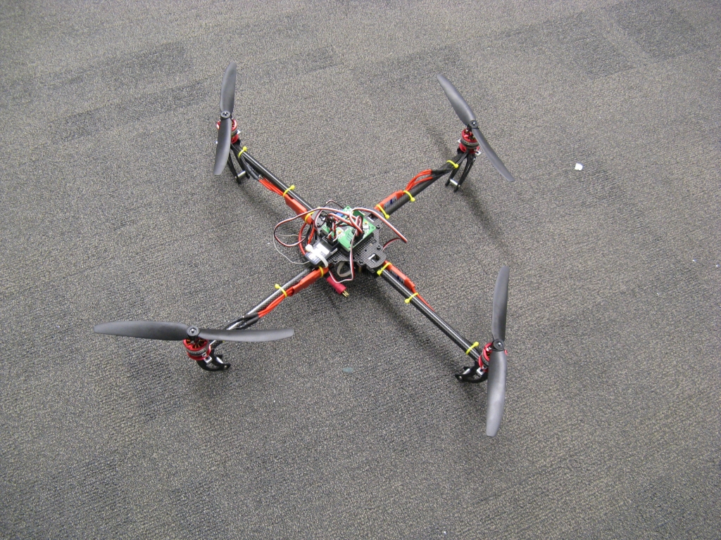
To fill the gap in my flying things fleet, I decided to put together a Turnigy Talon frame from Hobby King. I got to fly one that was put together by Daniel Kramnik (of Tesla Coil fame) and was very impressed with the quality of the frame. For $34, you get a real carbon fiber + aluminum frame. Add to that four $7 motors, four $14 ESCs, and $18 battery, a $3 bag of props, and $15 control board, and you get a complete mid-size quadrotor kit (bring your own radio) for $154.

Kramnikopter!

Here it is with 4pcb propped on it for size comparison:


The Talon frame is very impressive, even without considering the cost:performance ratio. It's stiff and light and it looks amazing. It also seems very durable - you'd have to crash pretty hard to break it and the landing gear is nice. When you take into account the fact that it's $34, it is one of the best deals I've seen.

The motors, on the other hand, leave something to be desired. They are the most inexpensive of an already low-cost/low-quality brand name, which means they have some issues. Mostly, I ran into axial alignment problems - the can and shaft are poorly constrained. They are also not balanced. If I were to replace one component right now, it would be the motors. They do look cool, though. 

For what it is, the KK board is an impressive deal as well. It's rate-mode only, so it can't do self-leveling, position hold, altitude hold, or any other more advanced features. 4pcb flies in self-leveling attitude mode, so returning the sticks to center means it tries to go to level (zero angle). So it took some practice for me to learn how to fly Kramnikopter in rate mode, where returning the stick to zero means zero angular velocity. You can see me learning the new input mode a little at the start of this video:


After filming the first half of that video with it, I decided to go ahead and attempt to fly my HD video camera. I have a long history of attaching my camera to things that move, but this would mark the first time that it's actually left the ground. The mount I made was pretty simple:

Kramnikam v-1.0
On one hand, the camera flew and survived. But it's not quite a cinematic experience yet. This camera weights exactly 300g, and it's just a little bit too heavy for this combination of motors and props. The resulting flight is very close to being unstable, since the motors are almost maxed out. The more obvious problem is that my initial vibration isolation solutions (foam tape, felt) didn't help much. So, lighter camera and softer mount seem to be the next steps. For now, I have a really nice medium-sized quad to play with.

Friday, December 23, 2011

More Sensorless

I'm still tweaking the sensorless routine for Pneu Scooter. The software framework for sensorless sinusoidal commutation and field-oriented current control is set, and now I am playing with the different parameters to see if they have the effects I think they should.

First, I hypothesized in the last post that the positive relationship between current and flux estimator offset (with respect to the Hall effect sensors), seen here, was due to underestimated inductance. At high current, the rotor electrical angle predicted by the flux estimator would lead the angle interpolated from the Hall effect sensors, which I trust to be more accurate. Based on this figure, if the inductance parameter is too low, the [-IL] vector will be too short and the estimated flux vector will lead the actual flux vector at high current. 

To test this, I changed only the L parameter in the sensorless code definitions, from 200μH to 300μH, leaving all other settings the same. After another 15-minute outdoor test drive, I plotted the flux estimator offset as a function of current once again. Here it is with the old data for comparison:


The effect is exactly what I thought it would be, flattening out the slope so that the offset is constant (near zero) though the entire range of load currents. I may have even gone a bit too far, creating a very slightly negative slope. But now I know that the inductance parameter has as predictable effect. The lead induced by using an inductance parameter that was 33% too low was about 20º electrical at maximum current. The error sensitivity is easy to predict using the vectors in this figure, but I will spare you the analysis in this post.

A closed-loop flux observer, which some day in the future I will certainly try out, would seek to minimize the effect of an over- or under-estimated inductance parameter. The ultimate goal would be plug-and-play sensorless that adapts to any motor on the fly. But for now, I can live with nicely-behaved dependencies like this. Though, without the parallel-processed Hall effect sensor data, I would be lost as to how to characterize any of it.

I also tried out the sensorless controller on a different motor:


The thing clamped to the table is Kitmotter, a demonstration motor with very similar characteristics to Pneu Scooter's wheel motor. They have virtually the same measured inductance. Kitmotter has a higher resistance, which I modified in the sensorless code definitions for this test. It also has a lower torque constant, which is not an explicit parameter in this sensorless algorithm. What it does mean, though, is that the flux magnitude should be lower:


And in fact it is, by a small amount. It's also interesting to see that the general form of the flux estimates is very similar for both motors. In particular, the gap between about 200º and 210º shows up in both cases. This eliminates the possibility that the gap is caused by some asymmetry in one motor's winding. It could be current sensor asymmetry, though.

Kitmotter also accidentally allowed me to test the fast overcurrent shutdown. The dangling mess of alligator clips seen above was not the best idea, and when two of the phase outputs shorted to each other, causing a large spark, the controller shut down properly and gave an overcurrent fault. No dead FET.

The next parameter I want to tweak is the low-pass filter time constant, which affects the low speed performance of the sensorless control. I mentioned that the low-pass filter causes the flux estimator to lead the true angle at low speeds, and showed the offset as a function of speed. Here it is again, but in pseudo-3D:

Is this nauseating?
Below 200rpm, the flux estimator angle is greater than the Hall effect sensor angle (trusted to be the true electrical angle). This causes the data, which should lie on the x = y plane, to slope off to the left at low speeds. Making the low-pass filter time constant longer should flatten out the plane and improve the low-speed torque. A lower "valid data" speed for switching to sensorless control will make start-up ramping, when I get around to that, just a bit easier.

I'm also worried about high-speed operation, which was the problem that magically disappeared when I made several code improvements. But, I'm still working with relatively slow motors, having commutation frequencies of 200Hz or less. I'm interested to see how things change (probably for the worse) when I try to run a non-direct-drive (indirect-drive?) motor like that of tinyKart, which can hit 750Hz or more.

More testing to come...

Sunday, December 18, 2011

Sensorless Pneu Scooter: Part 2

Pneu Scooter is now Sensorless Pneu Scooter! (Which means I can ride it again.)

This is the follow-up to Part 1: Where I make my code much fancier. Most of the work of the past two weeks went into setting up a new timing structure for the control code, which is summarized by this graphic. The controller has a fast loop, which runs at 15.625kHz, and a slow loop, which runs at just under 1kHz. The slow loop handles the computationally-burdensome Field-Oriented Control (FOC) calculations, and hasn't changed since I first implemented it on B.W.D. long ago. The concept of FOC is summarized in these two posts, and is shown in this, the first of many neon graphics I color-inverted for this post:


FOC seeks to keep stator current, I, in phase with back EMF, E, which is equivalent to saying that it keeps stator flux 90º ahead of rotor flux. This produces the most torque per amp. To keep the current and back EMF in phase, the voltage, V, is phase-advanced by the controller to counteract the effect of inductance. 

All these quantities are treated as vectors (really, the magnitude and relative phase of a set of balanced three-phase sine waves). The coordinate system is aligned with the rotor's magnetic field (hence, "field-oriented") and the axis on which the rotor flux is at a maximum is called the Direct (D) Axis. The Quadrature (Q) Axis leads the D-Axis by 90º electrical in the direction of rotation.

Because the coordinate system is locked to and spinning with the rotor, the position of the rotor must be known with good resolution for any of this to work. Previously, I used Hall effect sensors and time-based interpolation to derive the position. But, as the name would imply, Sensorless Pneu Scooter needs new tricks that do not rely on Hall effect sensors. To obtain the rotor position, the fast loop estimates flux on all three phases. The flux estimator I chose to start with is a very simple one:


It's an "open-loop" flux observer that derives the rotor flux linkage from measured currents, driven voltages, and a good estimate of the motor's resistance, R, and inductance, L. The vector version of this flux estimator is shown in the image above. Note that the integral of a given vector is another vector which lags by 90º and is scaled by the angular frequency:


Which brings up another good point: Unlike back EMF, flux does not vary with speed, so the flux estimator should produce a constant magnitude at any speed. As the V and E vectors increase in magnitude, the scaling by ω keeps the integral-form from growing.

The figure above is actually somewhat misleading. For one, the flux estimator doesn't run in the rotating D/Q coordinate system, but rather in the stationary frame, on each of the three phases independently. Also, the estimated flux on each phase is a scalar quantity; it's just the magnitude of the rotor flux seen by that particular motor phase at that particular instant. To derive position from this, I take an unusual approach of watching for flux zero-crossings (with hysteresis) and feeding these transitions to the same interpolation routine that my Hall effect sensors would have gone to.

In this way, the flux estimator is always running in parallel with the Hall effect sensors and control can be given to either one at any point in time. Additionally, they can be compared to each other. So, as I've been test-driving with the sensorless position estimate in control, I've been logging data from both. Cue the rest of the neon graph sequence:


All of the the data in this post was recorded during a five-minute outdoor test drive with the sensorless position estimate running the field-oriented control. The top plot above shows effective regulation of Q-Axis current to follow the throttle command, and the D-Axis current being held close to zero. The bottom plot shows the speed estimates produced by both the Hall effect sensors and the flux estimator. (Both calculate speed by measuring the time for one full period of rotor flux.) They are nearly identical at all speeds, including below 100rpm.

Speed is not sufficient for control, though; the flux estimator needs to be able to accurately derive the rotor position. Comparing the rotor position derived by the flux estimator to that of the Hall effect sensors reveals the following:


The ideal case would be a straight line with a slope of one, indicating perfect agreement between the flux estimator and the Hall effect sensors. There is a good deal of noise in the position estimate, but the general 1:1 correlation is there. The flux estimator angle leads the Hall effect sensor angle slightly, shifting the entire line upwards by about 15º. This is not necessarily the fault of the flux estimator; it could be interpreted as the Hall effect sensors being about 15º behind neutral timing.

To get more of a feel for the source of the noise around the 1:1 line, I plotted the relative phase offset between the flux estimator's angle and the Hall effect sensor angle as a function of a few other quantities. First, speed:


There are several interesting bits of information in this plot:
  1. At any speed, the band of uncertainty in the position estimate is still about 30º. Therefore, there must be factors other than speed which cause offset in the position estimate.
  2. The bulk shift of 15º (flux estimator leading Hall effect sensors) is clear in this plot too.
  3. At low speeds, the flux estimator leads the Hall effect sensors even more. This one is easy to explain. Instead of a pure integrator, I implemented a low-pass filter on (V-IR) as part of the flux esimator:
Pure integrator.
Low-pass filter.
The low-pass filter is used to keep the integral from drifting away. It's combined with a gain of τ, the filter time constant, so that at high frequencies it looks like a pure integrator. But at low frequencies, it has less than the -90º of phase a pure integrator would give:


At the corner frequency I chose for the low-pass filter, 0.053s, the low-pass filter causes the flux estimator to lead significantly at low speeds. The blue line in the offset vs. speed plot above is the theoretical lead induced by the low-pass filter. Setting the filter time constant to be longer would push the speed at which lead becomes significant down lower. Since the data seems to clearly show this effect, I would like to run some tests where all I change is the low-pass filter time constant. Obviously a longer time constant would be better for low speed operation. Integral drift might hurt the performance overall, though.

I also plotted the offset between the flux estimator angle and the Hall effect sensor angle as a function of load (Q-Axis current):


Here, another clear trend was revealed: the flux estimator lead increases with current. My hypothesis on this one is that the inductance estimate is low. In the first graphic of this post, the -IL vector would be too short if L were underestimated. This would cause the estimated flux to be somewhere in the upper-right quadrant, leading the true flux, which is on the D-Axis. Again, since the data shows a very clear trend, I would like to run some test where I vary only the inductance parameter to see if I can flatten out this line. 

This particular dependency (position error as a function of load) is one that I think can be avoided as I pursue more advanced sensorless algorithms. A "closed-loop" flux observer would be able to more readily handle misidentified motor parameters by using feedback to adapt the motor model or negate some of the effects of the misidentified parameter. Another valid option is to have the motor parameters self-calibrate, either at power-on or dynamically as it runs.

Lastly, my favorite graph of all:


I had the data spit back the actual flux estimate on Phase A along with all the phase currents. Plotting the Phase A flux as a function of the flux estimator's angle reveals a very nice sinusoidal flux that peaks at 180º and has an amplitude of about 15-17mWb. Not coincidentally, this is close to 1/7th of the motor's per-phase back EMF constant of 0.105V/(rad/s) = 0.105Wb. (The motor has seven pole pairs.)

The three phase currents are also plotted and are bounded by nice 40A sine waves, representing maximum positive throttle. Phase A's current (yellow) leads Phase A's flux (white) by about 90º, as it should if the field-oriented control is doing its job.There's a very interesting gap in the flux estimate angle just before 210º, which is also seen as a "staircase" effect in the flux estimator angle vs. Hall effect sensor angle plot. I still haven't tracked this one down or formed a theory about it yet, but this convinces me that it's an issue inherent to the flux estimate, since this plot has nothing to do with the Hall effect sensors.

Altogether, this "simple" sensorless routine has been working very well since I modified the controller timing. I can't say I understand exactly why (or even if) the changes I made to the loop timing caused it to start working, but I'm happy that it's now producing useful data and that I have new tests to try out. 

I'm even more happy that my Pneu Scooter riding ban can be lifted since it's now capable of propelling itself in 100% sensorless mode.

Saturday, December 17, 2011

Sensorless Pneu Scooter: Part 1

After just about one month, my voluntary moratorium on Pneu Scooter riding is officially over. Yes, that means it is now Sensorless Pneu Scooter. Even though I was distracted by flying things for a short period of time, I have made steady progress on working out the software kinks to get my first attempt at a sensorless field-oriented control strategy up and running. This is a two-week update, so I think I'll have to split it into two parts. The first part here explains most of the code tweaking I did. The second part, to come shortly, is when the sensorless control finally begins to work the way it should. How the two parts are related to each other, I don't exactly know.

Part 1: Where I make my code much fancier.

In the last update, I had been able to get Pneu Scooter running for a short indoor test drive on sensorless control. While it worked at low speed and low load, it was glitchy at anything above 20A and seemed to completely fail at 800rpm. These may have been related or unrelated problems, and I never got far enough into troubleshooting it to find out. Instead, while test-driving, one of the glitches took out the power stage, killing the FET, at least two gate drivers, and leaving a small crater where my DC current sensor used to be:


In a previous FET failure, the trace leading into the DC bus had blown, so I reinforced it with some copper braid. This moved the weakest link to the current sensor, I guess. It's worth noting that there is a 40A slow fuse in the system but it seems never to actually do anything during failures. Maybe time to go back to the magnetically-tripped circuit breaker switch. In any case, this board is toast. Even after I repair the power stage, it will only work with the DC current sensor bypassed completely. Possible motivation to design 3ph v4.0.

I switched to my back-up 3ph v3.1 controller and took some time to implement a few software improvements, including fast over-current shutdown designed to (possibly) save the FETs if (when) the sensorless control commutation glitches. I also implemented a better ADC sampling strategy to try to clean up the current measurements as much as possible. The goal was to sample phase currents at a time where no power switching is happening, since the switching transients can couple noise onto the current sensor signals.

First, the three PWM timers are synchronized (no easy task) and set to center-aligned mode, producing nested and symmetric voltage ouputs. In addition to reducing ripple on the DC bus capacitors, this has the benefit of creating a guaranteed point in time where all three PWMs are off. This is where I wanted to trigger the ADC to sample phase current. The STM32F103 has all sorts of interesting timer and ADC setup nuances that I discovered. After several days of messing around with timer and ADC configuration registers, I got to this:

Scopemas Tree.
I had to overlap the three voltage outputs to get all the traces to fit on the scope. Here, they are running with duty cycles of 25%, 50%, and 75%, just to illustrate what center-timed PWM looks like. Timer 1 is the master and the other two are synchronized to it. I set up an unused Timer 1 compare output as the trigger for the ADC, and I configured the dual ADC so I can convert two measurements simultaneously. I group and order the measurements as follows:
  1. Phase A Current & Phase C Current
  2. DC Current & DC Voltage
  3. Throttle & Nothing
The phase current measurements are most important, so they go first, triggered just before the center of the "off" portion of all three PWMs. The other measurements are more heavily filtered in hardware and software, so I don't care about protecting them from the switching transients. With my ADC configuration, it takes about 1.7μs to sample the two phase current analog signals. So, I set the ADC trigger to occur about 0.85μs before dead-center and expect it to finish 0.85μs after dead-center. After that, there is about another 2μs of conversion time, when the ADC translates the sampled voltage into a digital value. Then, an interrupt is triggered which stores the result in a variable. Zooming in on the center of the PWM, the timing of the first two sample-and-converts is something like this:


This scope plot also shows the motivation for sampling the phase currents away from the transitions. The tiny bits of ringing at each switching event show up everywhere: on other voltage outputs and on the digital line being used to illustrate processor timing. So, by leaving a window where all three PWMs are off and sampling the phase currents exactly in that window, the noise is hopefully reduced. The width of this "all-off" window has to be just a bit wider than the ADC sample time of 1.7μs, so perhaps 2μs. That limits the maximum duty cycle at 15.625kHz to 2μs/64μs, about 96.8%. Since the gate drivers are bootstrapped anyway and need some off-time to work at all, this seems like a reasonable limit.

After the three sets of ADC conversions, the fast loop is triggered and runs the sensorless field-oriented control routine using the freshly-converted current measurements. I also added some fast over-current shutdown code to kill the gate drive if any of the phase currents or the DC current exceed a maximum limit, positive or negative. Hopefully the combination of cleaner current measurments and shutdown within 64μs of an overcurrent fault will have some chance of saving the FETs if there is a controller glitch.

In case the last 1,000 words weren't very clear, here's a graphic showing the controller timing in its entirety:

(Click to enlarge.)
There are still some minor tweaks I want to make to the code. One way to save a ton of time is to use the Direct Memory Access (DMA) peripheral to automatically store ADC results in memory. Theoretically, this would cut the entire ADC block down to about 10μs. I'm also still running at only 32MHz. I don't need it yet, but the processor is capable of 72MHz in case I want to add more fanciness to my fast loop.

But for now, this setup seems fine. After loading the new version of the controller, Sensorless Pneu Scooter magically started working the way it should. I didn't think I had changed anything fundamental, but the performance is much better than it was before, almost indistinguishable from the previously-sensored Pneu Scooter. I've been riding it around for a few days now with no problems.

In Part 2, I'll get to the sensorless scheme itself and the data I've collected during my few days of test driving...

Sunday, October 9, 2011

Singapore Post

I was in Singapore again last week for the Singapore University of Technology and Design's first ever Open House.


When I went to Singapore last year, SUTD had just the two upper floors of a Chinese language school, mostly for administrative offices. Now, it has fully moved in to the interim campus, part of the ITE Dover Campus. We built up a small workshop ("the shed" or Gecko Works) at the interim interim campus, which has now been transplanted to a room at the interim campus:


It was cool to see the shop space I helped put together actually being used by future SUTD students and faculty to work on projects. I was expecting the interim campus to have a full shop, since it was formerly part of a technical institute, but it seems Gecko Works is still the primary fabrication space for SUTD. That makes our trip last year seem like a pretty good investment of time, actually.

As you can see in the above picture, Charles and I significantly increased the number of moving vehicles on campus, as usual. But in fact, some of the future SUTD students have been forming an Electric Vehicle Team of their own, using an electric bike we got from MKP Bikes last year as their first vehicle. It's been converted to a chopper bike, and now runs on a frightening amount of lithium polymer battery. You can see it towing half of the SUTD student population here:


Also featured in the video above are a fire ant-motivated top speed test of Pneu Scooter and Charles taking RazEr Revolution's name literally.

Pneu Scooter's officially-measured fire ant-induced top speed: 21mph.
Pneu Scooter actually took its very first test drive in Singapore last year. I finished building the frame and began testing on my 3ph v3.x line of controllers during my last trip. Unfortunately, the v3.0 controller had serious electrical noise issues, so I redesigned it when I got back and wound up with the v3.1, which has been ultra-reliable for almost a year now...

...and then two of them broke on this trip. I don't really know what happened since both times it was being ridden by someone other than myself. (Not that I would know what exactly caused the failure if I was riding it, but I could at least eliminate some possible causes.) My theories are:
  1. The ambient temperature in Singapore is just that much higher than it is in Boston, and the FETs failed due to thermal overload after basically racing it around all day.
  2. Since replacing the rear wheel a few weeks ago, the motor timing had shifted enough to cause commutation failure, leading to a destructive current spike.
I would weight theory #2 a bit more heavily since both controllers (the original and the spare) had the same phase fail. In any case, having burned through even my spare controller and having neglected to pack an extra IXYS module, I went back to MKP Bikes for Plan B: an off-the-shelf e-bike controller similar to the one I used in Singapore last time when my controller also failed. With that, I was able to get through the Open House. When I got back to Cambridge, I promptly changed the FETs on my controller:

Precision MOSFET removal tool.
All the gate drive was in working order, which is unusual after a FET failure. I re-timed the motor and have been riding it around with no issues, so I still have no idea what the problem was. I am going to pretend that nothing ever happened. But I did buy all the GWM100 IXYS modules remaining on the internet.

Scootering around at the Open House was not the only thing I did in Singapore for a week. Earlier, we visited a place called evHUB, which is a Singapore-based electric vehicle conversion and R&D house. They  have a somewhat hidden EV showroom/dealership with the name FSG Mobility Concepts, where I continued my trend of finding Tesla Roadsters scattered around outside the US.


In addition to the Tesla, FSG also carries the YikeBike. Rather than dedicate a paragraph of this post to describing the YikeBike, I'll just put in a video of us attempting to ride it:


I think the evHUB crew had an easier time learning how to handle Pneu Scooter than I had learning how to ride the YikeBike. Also the YikeBike is more expensive than Pneu Scooter by about the same ratio as the Tesla Roadster is to the YikeBike. So I'll stick with the kick scooters for now.

I also brought over 4pcb, my mini PCB quadrotor. It still doesn't fly spectacularly, but I wanted to bring it because I was meeting up with Ali S. to see his somewhat larger quadrotor in action...

Recursive quadrotors...
The exhibition hall actually turned out to be a perfectly reasonable place to fly a mini quadrotor and a perfectly suicidal place to test the one with 10" blades. For that reason, the mini one got a bit more air time. Here it is taking a few short hops:


It still needs work. After returning, I replaced the one weak motor and it at least hovers level now. But at some point in the near future I will replace the IMU with a different board. Not because I think it will necessarily handle the vibrations better, but because I am just sick of dealing with this one. And because Sparkfun doesn't make this one anymore.

I also got to visit most of my favorite Singaporean hobby shops and industrial centers. (I am such a bad tourist...) So overall, another successful trip to Singapore. I don't know how frequently I'll be going back, but I'm sort-of used to the climate and I seem to have a system for dealing with jet-lag. (I just sleep for the entire 25-hour set of flights.) Soon, there will be actual students and classes at SUTD, so maybe I'll go for an entire semester next year.

Because clearly this is my type of university.
For now, though, I have resolved to stop doing anything resembling a demo/expo/faire/whathaveyou for at least a few months. For one, I'm tired of answering misinformed technical questions from the slightly-more-tech-savvy-than-general public. I might just sound cranky but there's only so many times you can explain that MEMS rate sensors are not the same as flywheel gyroscopes without going crazy. Secondly, I am tired of having my vehicles turned into amusement park rides and then having to repair them after every event. And most importantly, I don't actually get any work done on new projects when I'm constantly exhibiting old ones. It's fun, but I need a break, so no more demos until at least IAP.

Now, what was I working on?...