Friday, July 13, 2012

FFv1.1 Ground Firmware Testing / FFv1.2s

Charles was kind enough to volunteer his daily mode of transportation for motor controller testing:

Read: The previous controller melted, or something.
Melonscooter, so named for the "melon-sized" Turnigy C8080-170 brushless motor that drives it, has been through a lot of motor controllers. The C8080-170 no longer exists, but the longer variant, the C80100-130 is now available through Leaders Hobby (what you get if you send "HobbyKing" forward and backward through Google translate a few times) under the EMP brand name. I used to think this was the hardest motor to drive, within the set of small EV traction motors. Used to. Then I met this insane thing:

FreeFly David's custom e-bike motor.
After attempting to drive this two-turn monster e-bike motor with only marginal success, the C8080-170 looks rather tame. Especially since Melonscooter has fixed gearing and no freewheel, so it's entirely possible to kick start it. That, and the low-cogging 12-slot/14-pole configuration make it seem more feasible. The C8080-170's resistance (21mΩ line-to-line) and inductance are very low, but I had already pushed the overcurrent latching fault to 200A to deal with the current ripple on David's e-bike motor, so again this seems relatively manageable.

It looks much more legit with a 3d-printed case.
FFv1.1 is still undersized for the C8080-170 motor. Additionally, since Melonscooter runs a 40V battery pack, I'm using one of the FFv1.1 boards with the relatively wimpy 60V FETs (IPB034N06N3 G). Based on the e-bike testing, I decided the maximum phase current they would be able to handle for acceleration would be about 50A. At 3.4mΩ per FET, the conductive losses at 50A phase current add up to (3/2)*(50A)²*(0.0034Ω) = 12.7W. Add to that the switching losses, current sense resistor dissipation, and other parasitic resistances, and the power stage might be dissipating 20W or so of heat, which is a lot for a board with no heat sinks.

Tuning the sensorless FOC parameters for the C8080-170 took surprisingly little time, partially because I'm getting used to the steps required and partially because I already have good measurements of inductance, resistance, and back-EMF constant from this motor. It also helps that it could be push-start, since adjusting the open-loop ramp start takes a while. After a few iterations of parameter adjustment, it was ready for test driving:


It's way quieter than usual, due to the sinusoidal drive voltage. The current is low for what the C8080-170 can handle, so the acceleration is nothing spectacular. Although, due to a software error the acceleration currents in the video exceeded 50A by a bit. You can see the wireless data-logging software running in the video, but I stupidly overwrote all the test drive data, so I'll have to capture it again later.

The peak flux amplitude was about 5.5mWb. Multiply by 7 pole pairs to get the per-phase back-EMF constant, about 0.042V/(rad/s). That's peak line-to-neutral volts. Invert, divide by two, and convert units to get the approximate Kv: 124rpm/Vdc. This is substantially lower than the 170rpm/Vdc the motor gets with BLDC-style square wave control. Less speed per volt, more torque per amp.

The next step for FFv1.1 ground firmware testing will be upgrading to nicer FETs and improving heat sinking a bit. One FET option is the proven 75V IRFS3107-7, used on Cap Kart's half-bridge and the Victor 883107-7 controller. These have already shown that they can handle 75A acceleration current with no trouble. An even lower resistance option would be the 60V IPB017N06N3 G. It also has half the gate charge of the 3107-7, so it will cut down on the switching losses. I'm not sure I would use it with a 12S LiPo (44.4V nominal, 50.4V fully charged) system, but the current 60V FETs have proven sufficient for 12S A123 (39.6V nominal, 43.2V fully charged).

On to smaller things...

FFv1.1 (and v1.0, really, since it was virtually the same) have been very successful so far. The DRV8301 magic chip has proven its worth, since I have yet to see any noise problems at all. The target application for FFv1.0 and v1.1 was large multirotor motors, specifically for the CineStar 6, and I designed them with 20-30A continuous motor phase currents in mind. With good heat sinking or air cooling, they can probably handle 50A continuous phase current. But now I realize that it might be useful to have a smaller, lighter version for things in the 10-15A continuous phase current range. So it's time for a new revision, FFv1.2s:


The logic and gate drive sections of the board are exactly the same as v1.0 and v1.1. The power section has been entirely redone to use six Power SO-8 FETs. Power SO-8s are increasingly common thin, leadless SMT packages for power MOSFETs. There are a huge variety of lower-voltage FETs in this package including some amazing ones like the Si7192DP at 30V/1.9mΩ. They're also easy to heat sink from the top surface, since they're very thin. So even though the power stage looks disproportionately small, it should be able to handle a decent amount of power.

My target application for these is the smaller multirotor motors, such as the ones on my Talon quad. The FFv1.1 boards have already shown significant increase in efficiency on the Talon quad, but they eat up all their advantage by being much heavier than the Turnigy controllers it normally uses (65g from FFv1.1 vs. 19g for the Turnigy Plush 18A). I don't know if I'll get all the way down to 19g, but FFv1.2s should be close to that. Even though the board area is only 33% smaller, the weight should shrink by a lot more with the thin FETs and smaller capacitors.

Because the logic and gate drive section is the same as FFv1.1, it will still be a full-featured sinusoidal FOC setup with wireless capability through the XBee. (For minimum cost/weight configuration, the XBee will be left off, but it's useful to have the header there for wireless programming/debugging.) As usual, I will post the relevant design files pending testing.

Saturday, July 7, 2012

Flying Things Update

Last week I went to Seattle to visit FreeFly Systems, makers of the CineStar multirotors like the one I've been test-flying with custom motor controllers. It was my first trip to Seattle, or to the West Coast for that matter. I finally got to see some of the mountains that Tyler is always talking about.


One of the cool things I got to see in person is the CineStar 6 Heavy Lift configuration, seen here lifting a 30lb payload, or as the commenters suggest, "2 [RED] epics for 3D," or "like 90 go pro's." It's the same frame as the regular CineStar 6, but with beefier motors and bigger, more efficient propellers. As such, it should make a good load test for my FFv1.1 motor controllers. The goal would be closed-loop speed control tuned for that particular motor and propeller with an inner FOC current-control loop to keep everything happy and efficient.

Here is the CS6 Heavy Lift blowing some trees around:


In addition to doing some bench-testing with the CS6 Heavy Lift motor/prop, I got to test the FFv1.1 ground firmware on what might be the most difficult traction system one of my controllers has ever encountered:


This custom e-bike has every possible thing going against it as far as motor control is concerned. It's sensorless, so the controller has to ramp start. The motor has an integer slot, full-pitch winding, so there's massive cogging torque and the back-EMF is very trapezoidal. It's aggressively geared for about 35mph on 22.2V, so it requires a lot of current. That's okay for the motor, since it's got very low resistance and inductance, but the controller won't be happy about it.

Probably the hardest part for the controller, though, is the freewheel. Ramp starting into a freewheel is not fun, and push starting like my scooter is impossible. After a couple of days of tweaking and pushing the current limits up and up, we got it to ramp with about 75-100A and run with 50-75A, though not reliably. It was a good test of the hardware and ground firmware, though, and I'm sure it would have no trouble running Pneu Scooter now. It's a lot smaller than my 3ph controller line, so I might actually use it.

Most of the trip was related to flying things, though. Seattle and especially the surrounding area is a much more scenic place to fly things than Boston/Cambridge. If only the weather was nicer. We took a trip to Snoqualmie Falls one day in search of a spot to fly things.

What's that pink thing hovering around out there? Some kind of bug?
Overall, it was a fun and productive trip. I have some new directions to move in with the FFv1.1 controllers, which I'll be updating shortly. I'll be focusing on closed-loop speed control modes and a user-friendly configuration tool that will make setup much easier. I also plan to make a more compact power-side layout for lower-current applications like my Talon quad and other things.

Speaking of the Talon quad, when I got back from Seattle, I had three brand new KK2.0 flight controllers from HobbyKing waiting for me. The KK2.0 is a big step up from the original KK for not much more cost ($30 for the new one). It has a nice LCD screen and menu system for configuration, so no more firmware uploading and no more trimpot gain setting. It also has a three-axis accelerometer now, enabling self-leveling and "height damping."

The self-leveling feature is useful, but I would stop short of calling it attitude control. The sticks still command rotation rate, and the self-leveling acts over a long period of time to get back to level. True attitude control would have the sticks commanding angle and the quad would snap back to level "instantly" when the stick is centered. Even the slow self-leveling helps, though, when you're high up and can't easily see the attitude. And the height damping from the z-axis accelerometer is nice. It makes manual altitude holding a lot easier.

The new features make it easier to go high with the quadrotor, since you don't have to worry as much about it taking off in one direction when you lose track of the attitude:


MITERS has a bunch of flying things now, so we all went out for some evening test flying until it was too dark to really do anything:

Thursday, June 21, 2012

XBee 10C0 Firmware Fix

If you're like me and you've been working with XBee radios for a long time, then you may have encountered the 10C0 firmware problem. Some time in 2007-ish, MaxStream (now Digi) released a firmware upgrade for the XBee Series 1 (the 802.15.4 version), moving from version 10A5 to version 10C0. I diligently updated the firmware on all my XBees at the time, using the X-CTU configuration tool.

Many years have passed since then, during which I probably got a new computer. And at some point when I tried to move on to even newer firmware (10ED is the latest as of today), I found that the 10C0 firmware had disappeared from newer versions of X-CTU. And, because all other evidence that the 10C0 firmware had ever existed was also gone, it was impossible to read from or write to the XBees with that firmware version. This also made it impossible to upgrade the firmware to a newer, supported version.

Calls to Maxsteam/Digi were not very helpful - nobody seemed to know what version 10C0 was or why it had disappeared. The firmware list skips from 10A5 to 10CD. It's possible it was a buggy firmware and was taken down. Another story I heard was that it was a custom, OEM-specific firmware not meant for general release. In any case, it left me with a bunch of bricked XBees from the 2006 era.

No seriously...a lot of freaking XBees.
To be fair, they weren't complete bricks. They could still be used to talk to each other or to newer XBees with the same settings. They could also be configured manually through a serial terminal. They just couldn't be configured or updated with X-CTU, which is far more convenient. I still use them occasionally for simple projects or lend them out to people from whom I don't expect to get them back, but for the most part I have a bin full of not-very-useful 10C0 XBees.

...until now...

Here is the rough procedure I used to recover 10C0 XBees and update the firmware:

First, the root of the problem seems to be a missing "configuration file" for 10C0. So I found a folder full of things that seemed like configuration files. On my machine, it's under:

Program Files > Digi > XCTU > update > xbee

And it has two types of files, *.ehx, which I would guess is the actual binary file for the firmware, and *.mxi, which appears to be the mysterious configuration file. (It's ASCII-format text and has all the common settings listed.) The filenames have the format:

XB24_15_4_1xxx.mxi - XBee firmware version 1xxx.
XBP24_15_4_1xxx.mxi - XBee Pro firmware version 1xxx.

Missing are the 10C0 firmware files:

XB24_15_4_10C0.mxi
XBP24_15_4_10C0.mxi

If they're not missing, you might be having a different problem with uploading firmware and you should try other solutions. If the files are present but you've tried everything else, just delete them. Next, copy and paste the two 10CD firmware files into a separate folder. That's:

XB24_15_4_10CD.mxi
XBP24_15_4_10CD.mxi

In the new folder, rename them:

XB24_15_4_10CD.mxi --> XB24_15_4_10C0.mxi
XBP24_15_4_10CD.mxi --> XBP24_15_4_10C0.mxi

This isn't enough to turn them into valid 10C0 configuration files, though. Next, open each one in a text editor and edit the first line of the file to change it to a 10C0 configuration file:

Change the highlighted text from 10CD to 10C0 in both files.

Save the files and then copy them back into the original folder. These will be the dummy 10C0 configuration files. They're not perfect, but they seem to allow X-CTU to at least read to and write from the 10C0 XBees. Open X-CTU and confirm that you can read the XBee parameters and that 10C0 now appears in the Version dropdown box for both XB24 and XBP24 modem types:


After ensuring that you can read the parameters off the 10C0 radio, it's time the get the hell off that firmware ASAP. Change the Version dropdown to whatever the latest version is (10ED here) and check "Always update firmware", then Write the new firmware and parameters to the radio. I presume if you've made it this far, you know what's required for normal firmware updating. You need an XBee adapter that has the capability of updating firmware (DTR and RTS connected). It's a good idea do a regular firmware upgrade on a different radio as a test.

That's it. Enjoy your newly liberated XBees.

Monday, June 18, 2012

Get down from there, flux. You're not DC. You're not even a real measured quantity.

I recently fixed a nagging problem with the flux estimator, maybe the key part of my sensorless field-oriented control method. I'm in the process of writing up my current approach to sensorless control, so I've finally been generating some nice figures (ones that aren't made in PowerPoint) that will hopefully explain some of the math better than I can in words. Here's what the flux estimator looks like:

I guess if you use LabView this is what the code looks like too...
The flux estimator takes the phase voltage and phase current as inputs, and runs them through the constitutive equation for a round-rotor permanent magnet motor:


The result of the integral form of the equation is the phase flux linkage. This, like back EMF, contains information about the position of the rotor. Unlike back EMF, it doesn't vary with speed, which makes it a nicer quantity to estimate in most cases.

Doing an integration in software on real signals is not always practical. Ideally, the voltage and current are purely AC signals. But in real life they may have some DC offset for a variety of reasons. The current sensors may not be well-zeroed. Even so, the zero value may drift and there will always be at least some offset at the minimum resolution of the sensor. The voltage comes directly from the known PWM values, but it could also be biased due to rounding or other numerical issues.

Any bias on the input signals would cause a pure integrator to ramp the output up to infinity. For that reason, it's common to implement an integrator as a low-pass filter instead. At high frequencies, the a low-pass filter with the appropriate gain behaves the same as a pure integrator. That gain happens to be exactly the same as the time constant. Another way to think about it is that it's a pure integrator in series with a high-pass filter. This lead to the same transfer function and behavior: integrating frequencies above cutoff but attenuating any DC bias.

Attenuate...but not eliminate. 

The pseudo-integrator's DC gain is the time constant of the low-pass filter. So, although it won't ramp off to infinity, there will still be some DC bias in the flux estimate and it will get worse as the time constant for the low-pass filter is increased. This creates a bit of a trade-off, since increasing the time constant can help improve the low-speed performance of the flux estimator but will cause more flux estimate bias. Here's what the flux estimate looked like on the CineStar 6 QC-3328 motors at approximately hover speed:


There are a few things to notice. One is that the current waveforms are offset by at least 1-2A. (Look at the maximum and minimum current on each phase.) With a nominal phase resistance of 46mΩ and a filter time constant of 6ms, that would lead to a flux bias of (2A)(46mΩ)(6ms) = 552μWb. This is almost half of the expected flux amplitude, and it shows in the flux waveform, which is shifted up by quite a bit. The flux estimator has a saturation parameter, set to 1500μWb, and you can see the top of the waveform being clipped in this data.

Before attempting to reduce the current sensor offset, I took out the easier problem, which is the voltage offset. The 3-phase sinusoidal voltages are generated according to an 8-bit sine look-up table (LUT) which stores 256 numbers between 0 and 255 that trace out the amplitude of a sine wave. As it turns out, the actual average of these numbers is 127.5, not 127. This alone could shift the flux waveform up by (0.5/255)(25V)(6ms) = 294μWb. Just by switching to more precise math when calculating the voltage on each phase, I was able to eliminate this source of offset immediately:


The clipping of the flux linkage waveform at 1500μWb is no longer present, but there's still a good amount of bias. The next step I took was to have the current sensors auto-zero at the start of the program. It's an obvious and common thing that I neglected to do mostly because I kept saying, "I'll do it later," and I didn't realize how much it would matter to the flux estimator. After adding in a simple auto-zeroing routine, the flux is now back to dead center:


There's an interesting pattern present in this data which I think was caused by sitting at a very steady speed for pretty much the entire capture. Maybe now that the flux waveform isn't being clipped, things settle in to a more regular pattern. Or maybe I just happened to sit at exactly the right RPM for aliasing like this to occur. Either way, to confirm that it wasn't a problem I had just introduced, I redid the test and varied the speed a lot more:


Here, the current is more varied because I was accelerating and decelerating a lot. But the flux waveform is still clean and centered around zero. I wasn't sure how much this fix would improve the performance of the sensorless position estimate. For sure, you can hear the effects of the waveform clipping on certain motors. Here's a GIF of all three flux/current waveforms to better show the difference:


The third, most unbiased flux estimate also produces the most uniformly-spaced and scaled current signals, which is probably a good thing in terms of efficiency. The flux zero-crossings will be evenly spaced, which should improve the position estimate and the FOC. Initial bench tests seem good, but I'm really looking forward to putting the improved version on all six ESCs and doing another CineStar flight test, this time with a Watt Meter.

Sorry for the boring all-math post. But it was interesting to see an immediately obvious cause-effect relationship in this quick and simple fix.

Wednesday, June 13, 2012

CineStar 6: First Outdoor Test


After some indoor test hops and flight controller tuning, I was ready to take the CineStar 6 outside to fly for the first time on custom motor controllers. Flying outside is a little more risky: while there are fewer things to hit, there's also the chance for it to fly away (and never come back). And then there's the wind. In this video, the wind wasn't too bad, about 5-10mph. But it definitely changes the way everything performs and I had to turn the gains down a whole arbitrary-notch-of-controlledness from what they were set to inside.


Flying outside also revealed another difficulty: taking off from the grass. You can see at the end of the video that for every successful take-off I had, there were several bloopers. The problem is the landing legs getting stuck, not allowing the frame to rotate as the flight controller attempts to stabilize it. As a result, motors spin up or spin down drastically trying to compensate, but they instead just make things worse and it tips over or stalls a motor. The solution is probably to take off faster, but I'm not up to that level of confidence yet. So, I patiently tried a few times and eventually stuck something flat under one of the legs to help it out. Once it was in the air, though, it flew very nicely.


As flown, it was about 10.3lb (4.67kg). The shear mass makes it much less twitchy than the Talon quad I have, and more able to fight the wind. I didn't collect much data this time - just checking to make sure I can fly it. Other than somewhat unreliable startup exaggerated by the take-off problems, the motor controllers seemed okay. Next time out I will probably load it down with a camera, a Watt Meter, and maybe some supplementary landing gear that aren't like lawn darts. The rated maximum gross weight is 5.8kg. I won't be going very high, just because I'm not very experienced with flying it and it's a lot of weight to fall out of the sky. And all the load testing I need to do can be done below 20ft.

On the other hand, I would like to get some nice video from high up. After testing one at the 2.007 final contest, I decided that the GoPro was an order of magnitude better than the cheaper camera I had and lighter than trying to lift my Panasonic HDC-SD60. So, I got myself a GoPro.


For starters, I mounted it directly to the bottom of Kranmnikopter. (This is about two days after Kramnikopter had an unfortunate looping failure and was completely rebuilt.) The bottom mount will give a much better view than the top mount I tried previously, where you look through the spinning propellers. But, it meant moving the battery up top. It also means that the camera is lower than the stock Talon landing gear.


I'll have to deal with the landing gear problem later. For now, it just makes take-offs and landings more interesting:


The video came out okay. I especially like the 720p/60fps option (the clips with no sound). It makes the twitchy quad seem a lot smoother. There's definitely a noticeable waviness in this video that I didn't see in the indoor 2.007 video. It could be that the mount is different, or that the wind excites more vibrations at frequencies that bother the camera. (In the video, there's about a 10mph steady wind. Can you tell which direction?) I'll have to play with different types of foam mount to fix this. I also might look into a DIY lens change for the GoPro, since its narrow FOV options are not very useful.

This weekend, I'll be taking the Talon + GoPro with me to North Carolina where there are actual trees and open spaces. Hopefully I can get some nice video.

Sunday, June 10, 2012

CineStar 6 + FFv1.1 First Test Hops

And now we move from the very small to the very large:


This hexrotor frame is a CineStar 6, and has been the target vehicle for my FFv1.1 motor controllers, which so far have only been bench-tested on its motors and flight tested on a smaller quadrotor. The CineStar 6 and Cinestar 8 can do some real magic when combined with high-end HD video cameras. Here's the latest demo reel showing off some of the camera stabilization and rock-solid flight control they can achieve. (Embedding the video wouldn't do it justice - so go click the link!)

By contrast, my CineStar 6 is going to be a crude test mule for the motor controllers. For example, I may set the record for the highest airframe cost to flight controller cost ratio since I'll be using the same $15 KK Mulicontroller from HobbyKing that I've been using for Kramnikopter. I've already zeroed the gyros and calibrated the ESCs to this controller, and it saves this information in the ATmega328's EEPROM. So, even though I have to write new hexrotor firmware to the flash, I keep my calibration settings.

KK board, receiver, and six FFv1.1s ready for action.
Yes, the KK board can do hexrotor control! You have to find the firmware, which is not an easy task if you start from HobbyKing. But, the latest version is available at the KK Multicopter site here. "XXcontroller KR v.2.0" seems to have all the firmwares in a single zip file, so you can find the configuration you need and upload it using whatever AVR programming tool you have. The C source isn't as up-to-date (I could only find v1.4 on that page), but it was still interesting to skim through.

Since the point is to test the ESCs, I wasn't particularly concerned about weight while I was putting together the power system. The Cinestar 6 would normally fly with a 4S, 6.2Ah lithium polymer battery that weigh 580g. Instead, I loaded it up with a 6S, 6.6Ah lithium iron phosphate pack that's just shy of 1.5kg. I also added a 100A contactor and some massive power distribution cables:

Battery pack, contactor, and power distribution bus.
The contactor is run from a separate 4S, 1.8Ah battery that also powers the receiver. If the receiver loses signal, the contactor opens and the battery is physically disconnected from the motor controllers. This gives me a way to physically disarm the power system before approaching the hexrotor to unplug the battery or adjust something. I trust this a lot more than the KK board's software disarming feature, but if I were concerned about weight, a mechanical contactor would probably be out of the question. Small 50A automotive relays might be okay, though.

Since this was the first test flight of the FFv1.1 boards on the CineStar 6 frame, I wanted to stay near the shop so I could easily reprogram or fix any problems. But, testing a huge hexrotor indoors means you will have to be in the same room with it...


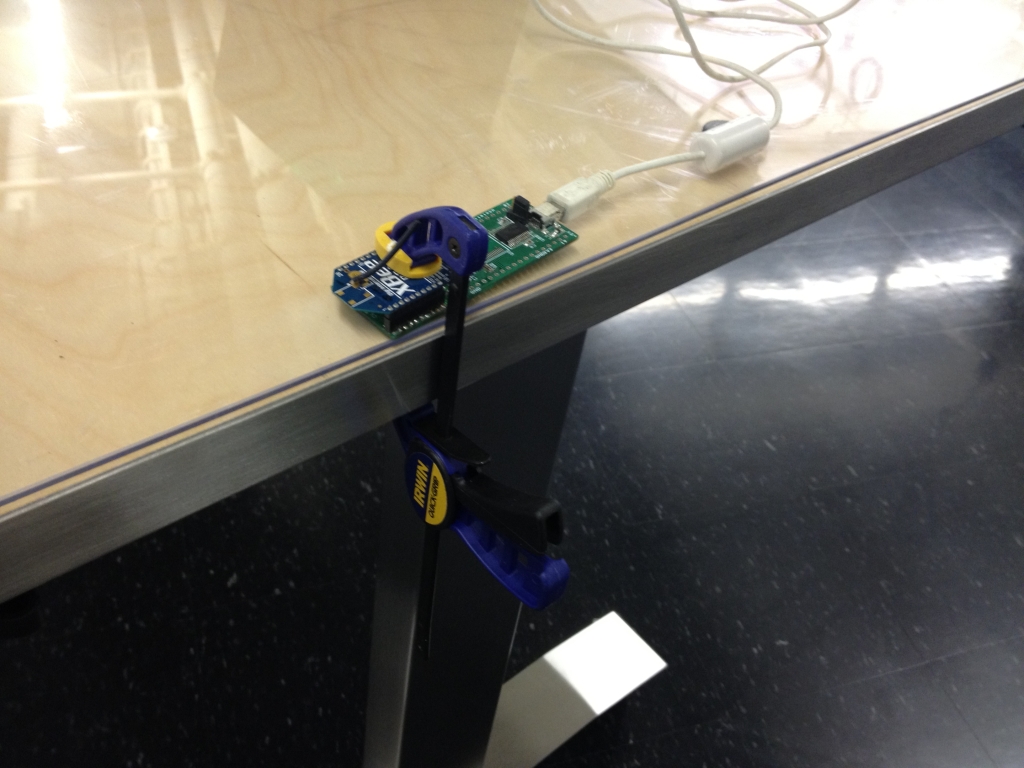
...unless you happen to work in a giant fishbowl with enough glass walls and doors to make you want to start writing equations on them in soap and muttering to yourself about secret codes hidden in your digital controls textbook. I set up my XBee receiver and data logging software so I could collect data from one of the six motor controllers. The XBee adapter board I use is rather old, though, and requires some manipulation to work properly:


At that point, I was all set to fly. Here's a video of the first couple of test hops:


In the first clip, the gains are a little on the high side, causing small oscillations which could go unstable when flying in ground effect or if a gust of wind disturbs the system. Turning the gains down made the flight less oscillatory, but also a little more jerky since the closed-loop tracking and attitude holding ability is reduced. 

I ran into a similar issue with Kramnikopter and the solution was to make the motor controller's input filter, which reduces noise on the PWM input from the KK board, faster. The faster filter had less lag and so the closed-loop system could tolerate a bit more gain without becoming oscillatory. With the CineStar motors, though, a faster filter has the potential to ramp the duty cycle so fast that the overcurrent protection is tripped, or the current sensors are saturated, either of which will cause a controller fault. 

In the test flight videos, the filter was a first-order discrete low-pass with a cutoff frequency of 5Hz. I will be trying some different types of filters, including a faster (10Hz) first-order low-pass and a non-linear slew rate limiter. I think the slew rate limiter might work best, since it attenuates large changes in input (ones that would cause overcurrent faults) but not small ones (like the closed-loop control signals).

For now, I got some good data on the operation of the ESCs. Here's the speed and current plots for the second of the two flight videos:


The hover speed is about 3700rpm for the 14x4.7SF props with a gross weight of about 4.76kg (10.5lb). The q-axis phase current for each motor is about 13A. I also installed a Watt Meter for the test hops. The average power draw for both flights was about 560W and the peak was about 630W. That's about 117W/kg average.

Here's a graph of the flux and phase currents vs. estimated rotor angle:


All the signals are in the right place, and it looks relatively clean. But there's definitely some bias in the flux estimate - it's shifted up by about 0.250mWb and the only thing keeping it from going further is the cap at 1.500mWb. This could be due to bias in the current sensors, so a self-zeroing start-up routine for them would probably help. Otherwise, a faster flux estimator filter would also hold the waveform in place better, at the expense of low-speed performance. So many tradeoffs... So much motivation to start working on Sensorless Gen2.

More testing to come.

Friday, June 1, 2012

4pcb Instructable


I finally got around to creating an Instructable for my PCB Quadrotor. 4pcb is a "low-level" build, perfect for people who don't like black-box components and want to do everything from scratch. But it's also simple to put together and Arduino-based for easy coding. I'd love to see a swarm of them flying around some day, but I really want to see derivative designs, like a hexrotor version!

I've updated the documentation on my own 4pcb page to redirect to the Instructable as the primary source of information for how to build it.

In other news, Talon hexrotor!


For $75, you get about $300 worth of carbon fiber and machined aluminum parts that fit together into a 625mm hexrotor. I won't be doing much with it for a while, since I have to get my huge hexrotor flying with custom ESCs, but I couldn't pass up the deal.