Friday, April 13, 2012

4pcb: 3S/370mAh Testing

Previously, I promised some PCB quadrotor testing on a 3S/370mAh battery instead of its former 2S/460mAh. They're both Turnigy nano-tech packs with a 25-40C discharge rating, so I am only trading mAh capacity for more voltage. In actuality, the 3S does store more energy (1110SmAh vs. 920SmAh to use a nonexistent unit of energy). Accordingly, it's also physically larger:

3S/370mAh (left) vs. 2S/460mAh (right)
And, it weighs more. The 2S/460mAh weighs 30.0g, while the 3S/370mAh is 36.6g. (In both cases, this comes out to about 113Wh/kg, which seems reasonable for a small power-cell pack where much more of the weight is packaging and connector.) Generally, adding 6.6g of weight to a micro quad is going to hurt a little, but if you're going to add weight somewhere, the battery is a good place to do so.

Theorem 1: "LiPoCopter Theorem" As the ratio of battery weight to total weight (LiPoCopter ratio) of an RC helicopter/multirotor increases, it is increasingly likely to be able to fly with properly chosen motors, props, and ESCs.

Proof: Consider the extreme case: a helicopter made out of a LiPo (possibly one of these, with two rotors attached to it like a LiPo-bodied Chinook). It is certainly possible to choose a set of components {motor, prop, ESC} which will allow this to fly. As any helicopter/multirotor approaches this ratio of battery to total weight, there will be some set of components which allow it to fly.

A respectable LiPoCopter Ratio of 26.4% (formerly 22.8%).
Of course, I don't get to choose an arbitrary set of components for 4pcb; I'm stuck with the existing motors, props, and controllers. I had a hunch that it would fly better, though, since the ESCs would very much like to see more voltage. They're rated for 7-42V, so running on 2S (7.4V) is very borderline. 3S (11.1V) gives much more margin for voltage sag under load. The weakest motor would tend to reach command saturation well before the 2S battery was dead, leading to drifting and ultimately instability.

The improvement on 3S was immediately apparent, with no additional work required. Here's a comparison of the motor commands for full-length flights on 2S and 3S:

2S/460mAh
3S/370mAh
In the 2S/460mAh flight, the average command to hover starts at about 200 (out of 255) and increases as the battery voltage drops, up to about 220. The problem is the front motor: after some time, it begins to saturate and when it does, it can't produce any extra thrust to counteract for disturbances. In flight, this causes the quad to pitch forward, especially on throttle-up, and makes it difficult to fly. You can see I had to land several times to let it re-stabilize. The total flight time was about 6 minutes, but the last 2-3 minutes were me fighting to keep it in the air. Usable flight time was about 3-4 minutes and even at the end of the flight, the battery was still above 7.4V (only 50% discharged).

The 3S flight is one continuous stretch of over 8 minutes in the air. The average command to hover starts at about 165 and increases to about 185 as the battery voltage drops. This leaves plenty of margin for stability, so even though the front motor command is still highest, it never saturates. The problem of uncontrollable pitch as the battery gets discharged is eliminated. One side-effect of having higher voltage is that all the gains are now too high, causing small/fast oscillations (compare the width of the lines in the above images). This should be easy to fix. After 8 minutes, all four motors start to taper off in power. And all of the battery capacity was used:

3S/370mAh after 8 minute flight. Total voltage: 9.02V.
Luckily, I bought four of the 3S/370mAh packs, so I now have enough capacity for 32 minutes of continuous flying. Just in time for demo season.


Sunday, April 1, 2012

TI Workshop + The Joys? of High-Speed Motor Control

I spent the past week at the Texas Instruments C2000 MCU Real-Time Industrial Control Training in Waltham, MA. It was really good workshop that I would highly recommend for anyone who wants to get into real time motor control. The next events are in Michigan and Wisconsin in May and June. The three-day event covers control theory on day 1, motor control specifics on day 2, and a C28x microcontroller intro on day 3, for which you get an F28069 Piccolo controlSTICK to keep:


In the interest of fair reporting, I will say the that feature set of the TMS320F28069 microcontroller does give it a few advantages over the STM32F103C4 that I currently use. It's a 32-bit processor (not ARM based) and can run at up to 80MHz. But, it has a built-in FPU and control-law accelerator, something not found until the F4 line of the STM32s. It also has more PWMs (16) and ADCs (16) than the smaller STM32F1s. As far as the available IDEs, I've used both IAR EW and Code Composer Studio before and I find them to be equally annoying. And I hate JTAG/emulated debugging anyway. 

I don't see myself switching away from the STM32, but I've had good experiences with the TI MSP430 line and I wouldn't hesitate to recommend those or the more powerful C2000's for people looking to escape from Arduinoland.

Since I'm always talking about how convenient it is to have a compact electric scooter that folds so you can take it on public transportation, I decided to try it out on my way out to Waltham. The bus from near me stops just on the other side of Prospect Hill Park from the TI offices:

No problem. This should be a nice traffic-free scooter ride through the pa-  
Oh.
I guess I neglected to consider the fact that Prospect Hill Park might actually be named for its predominant topographical feature. Pneu scooter is good at a lot of things, but hills are not one of them.

So I guess I'll be hiking.
Also, some of the paths are just dirt trails. The good news is that that's the TI parking lot right there.
Well at least I could have a fast trip down the hill on the way home - Oh no wait, it tore my brakes apart on the first two days. By the third day, with repaired brakes, I had pretty well optimized energy usage so that I could minimize hiking up the hill and coast the entire way down. Still better than driving in Boston rush-hour traffic.

Anyway, although all three days of workshop were great, I was especially interested in Dave (Wisconsin) Wilson's Motor Control Seminar. Most of the slides are available on his blog if you are interested. I learned a bit more about TI's InstaSPIN BLDC control scheme, and am beginning to sort out the various types of sensorless control methods.


One thing I picked up which I have to think more about is that what I have previously referred to as an open-loop flux estimator is in fact not as far different from a closed-loop observer as I had thought. The difference is more subtle and possibly less fundamental than it seems. For example, here is a closed-loop single-phase back EMF/current observer with a PI compensator:


With just one page of math, I can unwrap the feedback loop and rewrite it in the form of my "open loop" flux estimator, plus an additional low-pass filter. The closed-loop form still has the advantage of keeping an internal state for current estimate, which is probably way cleaner than the measured current. But they're not fundamentally different as I had once thought. Go figure... 

Maybe the important distinction then isn't between open-loop and closed-loop formulation for the observer. Maybe the fundamental difference is between observers that work only on electrical quantities and ones that include a mechanical state (speed, position). The addition of a mechanical state would almost certainly improve the performance of either observer, since it would anticipate the trajectory of I and E as the motor rotates. No wonder this is the type of observer described in the Book of Mevey, which has been right about everything else so far.

Back to reality.

My immediate task is to get this thing spinning:


After realizing that I wouldn't be able to hear anyone coming over the noise of the propeller, I added this:


In the previous post, I had gotten FFv1.0 up and running using Pneu Scooter as a test motor. The TI DRV8301 gate driver/everything chip performs well. But, the first time I attempted to run the motors on the hexrotor, I ran up against some not entirely unexpected issues with high speed control. At full speed, the electrical frequency of these motors can be 1,000Hz or higher. Every part of the control loop from the currrent sensors to the digital filters has to keep up with this, and in fact exceed it by a large margin to minimize phase lag. This is a tall order with a 15.625kHz PWM-limited control loop.

What I found on the first attempt is that at high speeds, the flux estimate becomes noisy and its zero-crossings, which are used to mimic Hall effect sensor transitions in my sensorless method, become blurry and unreliable. As a result, the position estimate would become noisy, which would lead to incorrect voltage vector placement. This leads to even more noisy current which leads to an even more noisy flux estimate, and so on. The physical result would be a motor that sounded very unhappy and current measurements that are all over the place starting at just under 5,000rpm. Under load, it could lose sync and crash entirely, surviving only because it was running on a current-limited power supply.

As an attempt to remedy the problem, I'm trying an idea I first thought of a long time ago for use with Hall effect sensor-based field-oriented control. The algorithm already uses a time-based interpolator to work between one flux zero crossing (or Hall effect transition) and the next. Instead of trusting the new zero crossing's position estimate 100% of the time, it's possible to use an IIR-style filter to merge the interpolator with the new position. Maybe this will help:

Maybe.
When the new flux zero crossing or Hall effect sensor transition comes in, it generate an angle (blue) which previously would be taken as the true angle. Now, that blue angle is averaged with the current estimate based on time interpolation (brown) to create the new estimate (purple). The relative degree of weighting for the average is set by a parameter, A, just like and IIR filter.

At high speed, when the blue vector is popping up at the wrong time due to noise, this filter will help stabilize the rotor angle estimate. And what a difference it made, without any tuning whatsoever. Here's some video of spinning up the larger prop, a 14x4.7SF:


One interesting thing is that I haven't even written a startup routine yet, but most of the times it starts just fine. I guess I'm used to vehicle controllers where if you don't write a startup routine they just sit there and buzz angrily. Also interesting is that once it does start, it can run at as low as 370rpm, which is about 7.5% of the top speed. So that would be my target speed for exiting the startup routine and entering run mode.

I can tell from the data that the angle filter helped a lot - the current is much cleaner. Here's a plot of the flux and phase currents with respect to the estimated angle:


Things are mostly in the right place and the flux estimate has the correct magnitude. (The flux is related to the motor constant or the rpm/V constant.) Something fishy is going on with the phase of the flux estimate. Its peak should stay right on 180º, since that's being used to define the d-axis. But instead it starts to shift forward at high speeds. As it turns out, I messed up the filter code a bit, so I'll have to go back and fix this one later.

For now, I also did some benchmarking against a Turnigy Sentilon 100A HV, a very good brushless motor controller. I measured (using a clamp multimeter) the AC RMS phase current and the DC bus current at different speeds running with the Sentilon 100A HV and with FFv1.0:


The not-very-interesting result is that they pretty much overlap so far. So I am at least not doing worse then good-but-dumb brushless DC controllers. It's definitely possible that any advantage of FOC will be lost in these motors because they are so efficient in BLDC mode already. Typically, high-speed low-inductance motors can operate very well with square wave drive. 

But there are other advantages that I'm still counting on. One which I was reminded of accidentally is that this controller can do four-quadrant drive. It can, in fact, brake so hard that it can unscrew the prop adapter and send a propeller flying across the room. Having braking should improve the response time of the motors to negative speed steps, which can help the control be snappier.

I've only just barely scratched the surface of the number of parameters that can be tuned. My next task will be to explore the effects of changes to the various motor parameter estimates, the filters, and the limits. Then, to see how it responds to more dynamic inputs. Then collapse everything into a simple enough interface that it could be used by other people. But so far, it's been a relatively problem-free controller build for once...

Friday, March 23, 2012

FF v1.0: First Spin-Up

Actually first, a little bit of micro quadrotor: I modified the timing of the TB6588FG motor control ICs on 4pcb. They were initially set by me to 0º (neutral) timing and I never thought about it after that. But since I discovered that command saturation on one motor is the cause of instability at low battery voltages, I thought I would give the timing adjustment a try. The theory: with advanced timing, the motor will generally spin faster for a given voltage command. The average command required to hover will be lower, so the margin left for control will be increased.

I ran it with 15º and 30º timing, flying from a full battery until it became too difficult to keep in the air (typically around 3-5 minutes). The average command did in fact decrease with advanced timing, although not by much:


Experimentally, the 15º setting seemed to be the best of the three. The 30º may have had more command margin for control, but it had shorter flight time, possibly because it uses too much current. The real solution might be to use a 3S/370mAh battery instead of the 2S/460mAh, since the TB6588FG would actually prefer more voltage and it would give lots of command margin.

Okay, I'm putting the micro PCB quadrotor away again, I swear. (I'll have to build a pico PCB quadrotor soon to keep up with the miniaturization trend.)

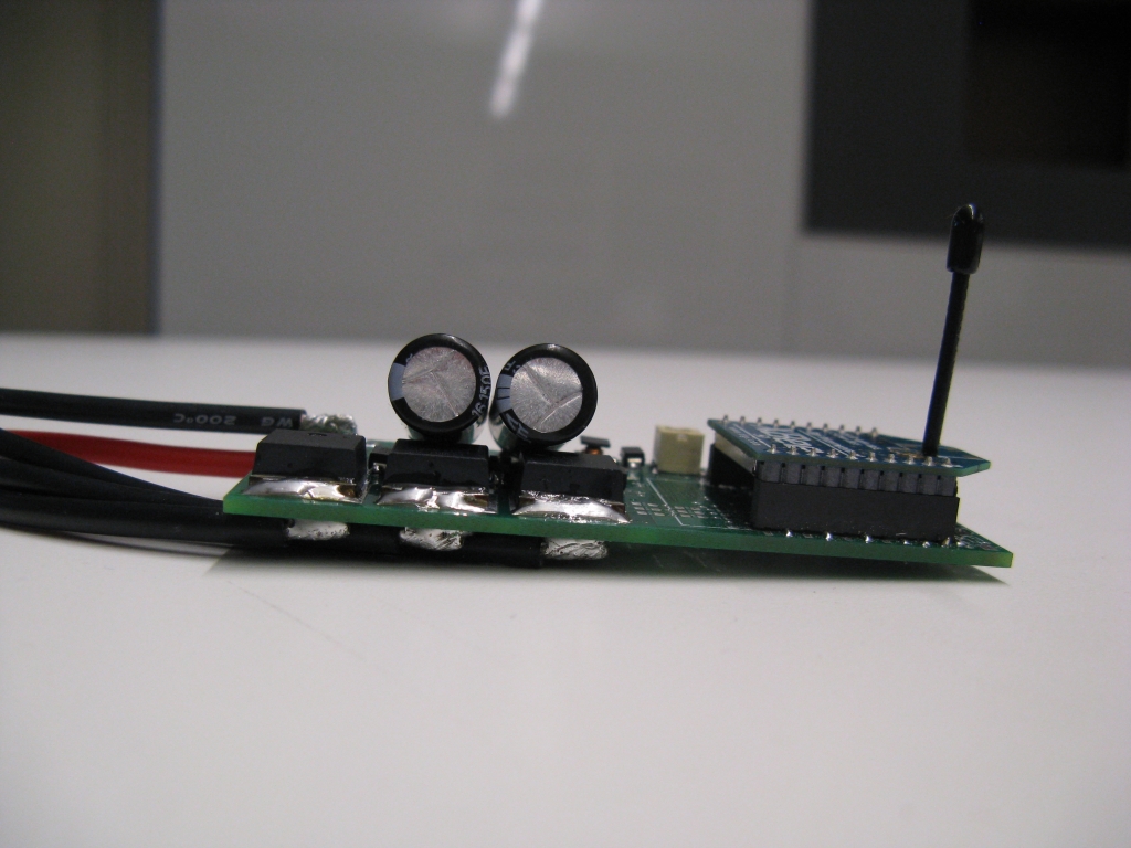
My FF v1.0 compact motor controller boards are in. It's the smallest (physically) motor controller I've attempted to build so far, with a footprint of 3.0"x1.5". Unlike my vehicle controllers, it's also designed to run without a heat sink, so it can be heat shrunk and buried inside of something.


The size and placement of the DC bus capacitors in this version is not ideal. I would prefer to have one or two long electrolytic capacitors sticking out the side in the direction of the wires, then maybe an array of ceramic ones mounted on the board. With that configuration, it would be only as thick as two sides of FETs. The XBee is an optional add-on that can be used for wireless programming, data acquisition, or radio control. Otherwise, it will have headers for PWM or serial-based control sticking out from the side opposite the power wires.

The most critical thing to test on this new controller is the Texas Instruments DRV8301 three-phase gate driver / dual current shunt amplifier / auxiliary buck converter controller / washer / dryer / smartphone / multi-tool. After a small amount of messing around with SPI code (the DRV8301 is configured by SPI, whereas the DRV8302 has hard-wired resistors for changing settings), I was able to get the gate drivers running. I had accidentally specified an insufficient amount of gate drive power supply capacitance, on the GVDD pin of the DRV8301, so I initially got a flood of GVDD undervoltage faults. After bumping it up to a 4.7μF, 16V 0603 (those exist?) I got much better results:

High side (top) and low side (bottom) gate drive waveforms.
High side turn-on and low side turn-off.
High side turn-off and low side turn-on.
GVDD ripple during low side turn-on.
First observation: Yes, I am using a new Tektronix DSO. It's...idk, I miss using the analog one. But this one can save images directly to a USB stick. The future is now.

The turn-on and turn-off times look appropriate for a 2A-peak gate driver on an IRFS3004-7 monsterFET. I get the impression reading the DRV8301 datasheet that this is slightly beyond the scale of FETs this chip was designed to drive. But it seems to handle it okay with the scaled-up GVDD and bootstrap capacitors. The last image is the GVDD ripple when all three low side FETs turn on simultaneously (also allowing the bootstrap caps to simultanously recharge). With the 4.7μF GVDD capacitor, the voltage dips from 11.5V to about 10V. The unvervoltage fault kicks in at 8V, so I think I'm still okay.

My shady math indicates that with these turn-on / turn-off times, the switching losses should be about 20W at 15.625kHz, 25V, and 50A RMS. Add to that about another 10W of conduction losses and the total dissipation at peak current would be 30W. I'm counting on the heat sinking of the wires, which I have no good way to quantify, so I'll have to wait and see if this is an acceptable amount of dissipation. It's also entirely possible that the whole thing freaks out due to noise way before 50A RMS.

So far, I've ported the code over from 3ph v3.1 (Pneu Scooter's present controller) to FF v1.0 for testing. Since I had already switched it to synchronous current sampling and sensorless control, the only real modifications required were changing around some pin definitions and adding the SPI configuration routine. After fidgeting for a few minutes with current sensor polarities, it now spins Pneu Scooter's motor the way it should:


And it is running entirely sensorless, using the same flux estimator as 3ph v3.1. One really interesting discovery is that it produces a nearly identical flux estimate vs. angle plot:

From 3ph v3.1.
From FF v1.0.
I'm not surprised that the flux estimate has the same magnitude and general shape, since it is the same motor. What's surprising is that the irregularities are the same. There's a break at about 200º that I have yet to find a good explanation for. Also, there are sections that are cleaner than others. I thought this might be due to differences in the current sensors or something, but this is entirely new hardware so now I am wondering if it's a software issue. I'll have to replicate the same plot for the other two phases to see if there are more clues to this mystery.

But why am I testing it on a scooter? I want to use it on a giant hexrotor. So far, all of my sensorless testing has been done on a 14-pole motor that maxes out at about 1,500rpm, so about 175Hz. Now, I need to run it at 10,000rpm with the same pole count. 1,168Hz commutation with a 15.625kHz switching controller is going to be a real challenge. So for the next short while I will be attempting to modify the software for high speed operation, and then testing it side-by-side against a commercial controller on some high-RPM brushless outrunners.

Once it's undergone sufficient load testing that I am convinced it won't just blow up, I will post the design files.

Next week I will be attending the Texas Instruments C2000 MCU Real-Time Industrial Control Training in Waltham, MA, where I will likely be ridiculed for using ST microcontrollers with TI gate drivers. In any case, I will hopefully learn some more motor control tips and tricks from the experts, including Dave (Wisconsin) Wilson from the TI Motorblog. I first found this blog when he posted the Ten Commandments of Digital [Motor] Control (Part 1 2 3 4 5), which is a must-read for anyone who wants to do motor magic. I'll likely make a summary post after the workshop concludes on Thursday.

Saturday, March 3, 2012

tinyKart: Snow Karting


More abusive testing of tinyKart during the (annual) March snowstorm.

Data:
tinyKart mass: 25kg
tinyKart mass after snow drifting: 26kg
percentage of mass gained in snow: 4%

Conclusion: Sherry W. is a pro. Also, we should make a 4WD version.

Wednesday, February 29, 2012

Flying Flux v1.0

New speed record: 9 days between motor controller designs.

3ph v4.0 was finished up last week, and even though it's an x.0 and I sometimes have bad luck on new major versions, I am pretty confident in the design overall. Pushing the 3ph line back to optically-isolated gate drive puts it in the same class as some of my most reliable controllers to date, such as Cap Kart's half-bridge, the Victor 883107-7, and 3ph v2.1. It's a low-risk modification that I think will pay off in cleaner analog signals and higher reliability.

And now that 3ph has become the stable design, I need a new experimental design. I've been meaning to try out a motor controller based on the Texas Instruments DRV8301 since it came out. This "everything chip" combines a three-phase gate driver with two current shunt amplifiers, an on-board gate drive supply with charge pump, and a separate buck converter for powering external logic. It seems too good to be true.

I've also been meaning to build an motor controllers to satisfy the requirements of RC aircraft, which is no easy task. I am much more at home with vehicle controllers where I can afford the weight of giant heat sinks, and the volume of separate logic and power boards, and the cost of fully-isolated gate drivers. But my RC friends have been urging me to try to execute advanced BLDC control with the power density and economics of commercial ESCs.

And then there's this:


Some clever people sent me a Cinestar 6 hexrotor frame, complete with motors, knowing that I wouldn't last long before deciding to build custom ESCs for it. To be fair, the commercial ESC that goes with it, a MikroKopter BL-Ctrl v2.0, is way more compact than anything I would make. But, it's an ATmega168/328-powered-square-wave-drive-ESC-with-direct-battery-voltage-derived-discrete-component-gate-drive that I can't bring myself to use.

So then, Shane, stop hiding behind massive heat sinks and low-RPM vehicle motors and design an ESC:

Introducing: Flying Flux v1.0
A quick overview of the features:
  • MOSFETS: IRFS3107-7 (75V) or IRFS3004-7 (40V), depending on the application. I love the D2Pak-7's. Cap Kart (all 300A of it) runs through four of these in parallel. There will be no heat sink other than the copper on the board and the wires coming off it, so I'm entirely relying on the low Rds to keep it cool. It's a heat-shrink-to-waterproof-style design.


  • Gate Drive: DRV8301, the everything chip, a 2A gate driver and a risky bet. I'm generally not a fan of everything chips because they put power and signal together in a way that makes EMI isolation very difficult. But it can't be any worse than driving MOFET gates directly with an ATmega328, right? I hope?


  • Current Sense: Two phase return current shunts, plus the internal amplifiers on the DRV8301. This is my first attempt at using current shunts instead of Hall effect sensors. Pros: potentially more accurate, conducive to synchronous sampling. Cons: Not isolated. That risk seems to roll up into the overall DRV8301 risk.


  • Logic Supply: The last trick up the DRV8301's sleeve, an on-board buck converter. It already has an internal gate drive supply, but this extra buck converter can be used to power the logic at 5V. It's compact and relatively beefy: up to 1.5A output.


  • Micro: Would I use anything other than an STM32F103 at this point? I can directly port SSCFOCC over to this controller, although it will need considerably work to get up to the commutation frequency required to drive high-speed outrunners (target: 1200Hz). This is the first motor controller I've done with an integrated STM32F103, not on its own separate logic board. Noise is by far my biggest worry. Every pin going toward the gate driver has a resistor in series with it and I do my best to keep the grounds separate, but I won't sleep as well as I do with optically-isolated gate drive and separate logic boards.


  • Inputs: Here is where this controller is much more capable than any of my previous ones. In order to accommodate as many possible applications as possible, I included every input I could think of. On the left side of the controller, there are three multi-purpose inputs that can be used for Hall effect sensors or A/B/Z encoder tracks or phase voltage sensing (on board) or as general purpose analog or digital I/O. On the top of the board are UART, I2C, analog, and PWM inputs for control. I2C and UART outputs can be used to send data back to the master controller. Oh, and I snuck on one more option:

    On-board XBee.
    The board can be programmed either with a standard FTDI adapter or no-touch over XBee. I was a little annoyed to find out the the FTDI adapters don't use RTS and DTR, the two useful signals for triggering the bootloader. They use CTS and DTR, and CTS can't really do anything. Why, Sparkfun, why? I guess it matches the FTDI cable. Why, FTDI, why? Anyway, this necessitates a boot mode button for wired programming. The XBee can handle DTR and RTS, so it can do completely wireless no-touch programming.
That's the design in a nutshell. As usual, I will post the schematic and build files once it's confirmed to be not DOA. It was a very complex routing job, but strangely cleaner/easier than 3ph v4.0. I think I was just on a roll from having designed two controllers in a row. I also learned a new EAGLE trick, which I call a bus rotation. Picture this scenario: you have four related signals (e.g. VCC, GND, TX, RX) and you want to change their order  for more convenient routing, specifically by shifting the sequence by one. You could do this with vias, but if you're right on top of something and can't spare the opposite layer space:

1206 resistor network to the rescue.
Of course, the goal will be to demonstrate SSCFOCC in a direct side-by-side comparison to a commercial square wave commutation, fixed-timing ESC. One nice thing about propellers (as opposed to scooters) is that they provide a very repeatable load that is (in the case of static thrust, as on a multirotor) only a function of RPM. So, I will consider the project a success if I can run the same motor and prop to the same RPM with less power input than a square-wave controller at optimal timing. Or maybe, to demonstrate the benefits of field-oriented control, run at several different RPMs in a reasonable operating range and show greater total efficiency.

There's a lot of work to be done on the way to that goal, though. So far, I haven't had much success with high-RPM field-oriented control. My RC car sort-of did it, but that was with Hall effect sensors and the rotor angle was still way off, so the efficiency sucked. I believe it's mostly a matter of filters and control, accounting for any sources of lag that the field-oriented control doesn't automatically take up. That, and pushing the control loop up to 32kHz, should be able to make it work. Fun.

For now, I can at least take a short break from EAGLE while I wait for the boards.

Monday, February 20, 2012

3ph v4.0

I've finally nailed down working Sensorless Sine-Commutated Field-Oriented Current Control (SSCFOCC) for Pneu Scooter, and I promise I will write up this (relatively) simple algorithm sometime soon before moving on to more complex closed-loop observers and other controls-y things that won't be of much practical advantage over this simple one, at least not for a while.

In the mean time, I've also finished the v4.0 design for my scooter-sized (~48V/40A) motor controller, with some tweaks to make it more optimized for SSCFOCC:


It's the same physical dimension as 3ph v3.1 (3.90"x1.55"), so it will be a drop-in replacement for the controller currently in Pneu Scooter. Other things that have not changed:
  • MOSFETs: This design still uses the GWM series miniature 3-phase full bridge modules from IXYS. Specifically, the GWM100-01X1, although it could also use the GWM160-0055X1 or the GWM200-004P3. They're hard to find, but I've stockpiled enough to survive until the end of the world.

  • Logic: Still using the STM32F103 on a Wootstick 2.0 because why would I change that?

  • Current Sensors: Two phase current and one DC current sensor using the ACS714 Hall-effect current sensors. They measure +/-30A, so in order to get to full operating current I can selectively bypass them with one or two 0.001Ω, 1% resistors each.
One thing that has changed is the current sensor layout. SSCFOCC relies on the current measurements to make an estimate of the rotor position, so cleaning up the current sensor signals as much as possible was one of my goals in this design. I know from experience that they pick up massive amounts of PWM noise. Better hardware and software filtering, as well as synchronous current sampling, have definitely helped. But it would be nice to tackle some of the noise at the source, with better layout around the current sensors:


It's a fact of life that the current sensors, particularly the phase current ones, need to be located directly adjacent to high dV/dt switching nodes. High dV/dt leads to capacitive coupling, and one way to protect sensitive traces from capacitive coupling is to shield them with ground planes. So, in an effort to minimize capacitively-coupled PWM noise on the current sensor signal wires, I did my best to shield the signal side of the ACS714's and the traces returning to the logic part of the board with ground. I don't know how much it will help, but it probably can't hurt.

The next big change is a return to optically-coupled gate drive. 3ph v1.x and v2.x, as well as most of my other motor controllers, have used optically-coupled gate drive. 3ph v3.0 and v3.1 used the IR21844 half-bridge drivers instead for compactness and low cost. But, this was before I realized that bootstrapped optically-coupled gate drive is possible and you don't need expensive high-side power supplies for everything. So with cost less of an issue, it just became a matter of stuffing six HCPL-3120 gate drive optocouplers onto the board. The half-bridge unit looks like this:


The input AHI is a 3.3V logic signal directly from the STM32F103. If AHI is high, the high-side optocoupler LED turns on. If AHI is low, the low-side optocoupler LED turns on. If AHI is high impedance, neither LED turns on and the half bridge is disabled. R69 and C54 form a low-pass filter that sets the shoot-through delay. Each gate gets a gate resistor, a pull-down resistor, and a 17V Zener diode. D2 is the bootstrap diode for the high-side driver.

The last big change is the addition of phase voltage sensing. To do this, I added a quad op-amp configured as a differential amplifier to measure Va, Vb, Vc, and the DC bus voltage with respect to power ground. One unit looks like this:


Differential measurement with respect to power ground (COM) should be more accurate when high currents push power ground and signal ground apart.

Phase voltage sensing opens up a number of interesting opportunities for 3ph v4.0. One is simple block-commutated sensorless, where one phase is left undriven (which I can do now, thanks to the tri-state-able optocoupled gate drive) and the back EMF is directly measured. I'm not sure why I would want to do this, other than for direct comparison to more advanced sensorless techniques with the hardware as a control.

Besides block commutation, measuring phase voltage may also be useful for rolling-start, which is something I do a lot on the scooter. Right now, I have to push against the resistance of the shorted motor until the current sensors pick up enough information to derive the rotor position. It finds itself at a very low speed, so this isn't a big deal. But, with phase voltage sensing, I could leave the phases off and use the back EMF measurement to do the same. The practical advantage is that you can freely kick up to any speed before applying power.

Another thing phase voltage sensing might be useful for is online or offline calibration, where the back EMF is measured and used to estimate the motor's torque constant or other parameters. At very least, it could be used as a single-purpose scope to make a plot of the motor's back EMF waveform, which is informative by itself.

All these extra features made the board a bit of a nightmare to route, with one of the highest component densities I've ever done:

Top.
Bottom.
I managed to cram the entire 15V and 5V power supply on the bottom layer, this time with ceramic capacitors. The six gate drive optocouplers barely fit on the top layer above the MOSFET. All the filters and logic are on the top layer under the STM32 board. There are also still inputs and filters for Hall effect sensors, even though I mostly plan to use this for sensorless control.

I'll sent these boards out right after the holiday weekend and as usual, post the schematics and other files when I confirm they work. Of course, the first sub-version of my boards are usually doomed to failure (3ph v2.0 and v3.0 didn't last very long, whereas v2.1 and v3.1 were great) so we'll see what happens.

Wednesday, February 8, 2012

Flying Things Update

Even though I haven't made any significant changes to 4pcb, I still feel compelled to dump the latest media into a post and update briefly on some of the other (other?) flying things. But first, some recent flying things that are not mine but are too awesome to ignore:

Cinestar 3-Axis Gimbal (Snow): Watch this in HD, with huge speakers. Now. It's impossible to explain in words how amazing it is. This is the Cinestar 8 with a 3DOF camera mount.

A Swarm of Nano Quadrotors: This was viral, so you may have seen it already. The Aggressive Maneuvers group from UPenn's GRASP Lab has released their newest video, which is near and dear to my heart because it uses nano quadrotors.

Nanocopter: Based on the OpenPilot platform, this one of the smallest quadrotors ever made. It's way smaller than 4pcb (2/3 the size and 40% the weight). The challenge is also issued for anyone to make a picocopter with 2" props.

Tricopter: A tricopter is an interesting controls problem, because it requires at least one servo to give it independent yaw control. This one is particularly light and stable, and has gone through many iterations to get better and better.

Tinycopter: Kinda like a a 5/4-scale 4pcb. Except it uses standard off-the-shelf components so you could build one without the need for a custom circuit board and surface mount soldering skills. Speaking of Tinycopter, I got a chance to do battle against the original Tinycopter:


The thing I learned is that there really isn't a winning strategy in Battle Quadrotors. Anyway, the miniature and nano-scale quadrotors tend to be very robust, so neither suffered major damage. Which got us thinking: what would it take to kill a miniature quadrotor?


Oh...that'd do it. The Tesla coil, built by Daniel K., emits enough EMI-inducing field to mess with sensors and possibly even radio control, but that's if it doesn't simply strike your airframe with an arc instead.

Sticking with the theme of destruction, there was a brief period of nice weather (nice = 45º and not windy) where I was able to fly one of my new flying things, a Hacker Skyfighter from Ryan A. I have only ever flown a small, ultra-stable indoor plane, so this was going to be an interesting challenge.


It's a flying wing, and set up for aerobatics. So if it looks like I know what I'm doing, rest assured this plane cannot help but do loops, rolls, and various other stunts while I try frantically to point it upwind and fly it away from the running track and back to the baseball field where I started. But, I will practice more and one day be good enough to actually land it.

I'm sorry, Ryan.
For now, though, back to multirotors. 4pcb has always been plagued by frame vibration issues, since it's made only from 0.063" FR4. I can see the props and motors wiggling when the frame hits resonance, and it certainly messes with the gyro readings and makes it more difficult to fly. Through a combination of mechanical and software measures, I've made the control mostly immune to these vibrations, but I thought it would be interesting to try to see the magnitude of the problem more directly.

To visualize the vibrations, I used a trick I've used before, strobe imaging. Ordinarily, you can set the strobe light to flash at the same speed as the rotating object and it will look stationary. But, you can also offset the strobe by a small amount in order to get a virtual slow-motion action shot. For example, if the props are spinning at 6000rpm (100Hz), setting the strobe to 101Hz will cause them to appear to spin (backwards) at 1Hz. Since the props create the forcing frequency that drives the frame, the vibrations should also be visible at 1Hz. Commence magic:


There are definitely at least two modes of vibration present. The first, which occurs at lower frequency, is a torsional mode where the arm twists. The second, a higher-frequency mode, is the arm bending up and down. The twisting mode looks more dramatic, and I would probably want to minimize its magnitude first to get the cleanest inertial measurements. I actually tried adding carbon fiber reinforcements:


This definitely stiffened up the frame, but it didn't actually fly better. For one, I've mostly solved the gyro noise problems already, so any gain achieved by reducing vibration will be marginal at this point. Additionally, the extra weight and airflow disruption from these supports may have been enough to push some of the motors closer to saturation, making the control feel softer. So I took them off.

In general, 4pcb's motors are running too close to the control limit (hover is just under 200 out of 250 on the throttle at full battery voltage). I replaced one motor that had bad bearings, and the motor I put in its place was weaker than the other three and saturated the control output all the time. After a day of troubleshooting, I swapped the motor yet again and now they are more well-matched. Still, when the battery begins to get low, one motor will saturate and cause it to feel very soft and drifty.

Unlike most of my project chains, v1.0 of this quadrotor has been very successful and I'm quite happy with the way it works now. But I'm looking forward to improving it a bit more and it's up to the point where I will need a new board revision to do so. The next version of the PCB quadrotor will have several improvements including:
  • Lighter weight. Microcontroller and power wiring integrated onto the board.
  • Higher voltage (11.1V instead of 7.4V). This will help with command saturation, giving more thrust margin for the 2000rpm/V motors, and keep the voltage away from the Toshiba chip's 7.0V minimum. To maintain the weight goal, it will have to be a lower capacity. But with a higher input voltage, the ESCs will draw less battery current, so flight time should be similar.
  • Closed-loop velocity control. No more motor matching. The Toshiba chips have a tachometer output that can be used as feedback to control prop speed, instead of open-loop motor terminal voltage.
  • It will also have provisions for altimetry and possibly a small camera mount.
I'm not sure when I'll get around to that revision, but for now, here's some fantastic processor-eating 1080p video of 4pcb v1.0 in action, thanks to Sherry W.:


There's also something interesting in the background of that video, and I posted a teaser a few posts ago:


I'll apparently be going directly from miniature quadrotor to giant freaking hexrotor without stopping in between. (Okay, there was this medium-small quadrotor I helped out with a while back.) But anyway, thanks to a donation from some very awesome people, I now have a Cinestar 6 frame, with motors. This is the six-rotor cousin of the Cinestar 8 from the snow video above. I am planning to use it as a development platform for custom ESCs in the near future. But for now I will be working with some people to get it flying with off-the-shelf hardware. Step one for me was a quick thrust test:


Yes, that is one of Cap Kart's old batteries being used as ballast while a 12" prop tugs on a spring scale. Note also the 80/20 bar blocking the hexrotor from doing a complete flip in the event of string breakage. The result was a thrust of about 2kg at max current with a 12x3.8SF prop. That's 10x the amount of peak thrust 4pcb puts out from all four of its props...

The frame + motors weighs 1.5kg. So even after adding in the props, ESCs, control board, and a reasonably-sized battery, it has enough thrust to carry some pretty epic payloads... I am both terrified and excited to see it flying.