Saturday, May 26, 2012

FFv1.1: Air, Land, and...well that's it.

FFv1.1 is the new minor revision of my small motor controller, which has so far tested successfully on the Cinestar hexrotor motors. The controller is sized for 24V (6S LiPo), 30A continuous and 60A peak current, and uses the same Sensorless, Sine-Commutated Field-Oriented Current Control (SSCFOCC) that I've been using on Pneu Scooter.

Unlike most of my other controllers, the FF series has power and logic integrated on a single board, optimized for size. This is enabled by the TI DRV8301 pre-driver, which so far has been working very well despite my fear of integrated power/signal ICs. Since I haven't had any obvious hardware problems, the only change in the v1.1 minor revision is the layout of the DC bus capacitors:


Instead of two 10mm electrolytic capacitors sticking up at a weird angle, I opted for a bank of large 50V ceramic capacitors, eight in total, on the board. The ceramics are more expenisve, but they should also improve the high frequency filtering of the DC bus. Because they are much higher cost per energy, I also planned to use a single large electrolytic capacitor sticking off the side of the board.

One problem with developing a controller that might be used on a hexrotor is that you need six of them. So, for v1.1, I got a 5x2 panel of boards from MyRO, a not-shady Chinese board manufacturer (~2 week turn). At this point I should thank the folks from FreeFly Cinema who donated the Cinestar frame and backed the first round of FF controller development.

Here's the fresh panel:


The individual boards are v-scored, so they're easy to break apart by hand. One reason I wanted to get the boards as a panel is so that I could batch-process the soldering. And damn, it was a lot of soldering.


I mostly solder everything by hand with a magical Weller WD1001 station, but in order to do the DRV8301's power pads, I used paste and a reflow oven.

95% finished Side 1. This side has the XBee radio headers.
95% finished Side 2, with the microcontroller and gate driver.
In total, it took about 14 hours of soldering spread over three days and not including the time to attach wires and connectors to the finished boards. It's probably the second longest soldering job I've ever done. But I think I probably cut the time in half by doing the whole panel at once instead of working with individual boards.

The finished product, without heat shrink covering and connectors, looks like this:


The three blue wires are motor phase outputs, the red and black are DC inputs, and the three-wire connector is the servo-style PWM input. There's also a 6-pin header for programming with an FTDI adapter, although so far I've been programming wirelessly by XBee. In this configuration, the total footprint not including wires is 4.25"x1.5"x0.5". Without the programming header and electrolytic capacitor, the minimum footprint is 3.0"x1.5"x0.5". The weight including wires and connectors is about 65g.

For the six boards that will wind up on the hexrotor, I used IRFS3004-7 FETs (40V, 1.25mΩ) and a 680μF/35V electrolytic capacitor. The remaining four use Infineon FETs, IPB034N06N3 G (60V, 3.4mΩ) and 330μF/63V capacitors. These are prototypes for a higher voltage, lower current version, and in particular I wanted to test them on some ground-based vehicles. I left these four connected from the panel:

Quad-core motor controller.
The reason for this is because I wanted to test them on a 4WD vehicle:


The vehicle, ChibiKart, is a 4WD miniature go-kart with custom in-wheel motors. The controllers are shady eBay specials that do sensorless BLDC at about 25A peak for $28. While I definitely can't compete with them in cost, I can match their power and four FFv1.1 boards could fit in a single one of their enclosures. (I may actually try this, now that I think about it.)

It's probably a better idea than a McMaster-Carr bag.
After some initial testing (video below), the controllers performed well with 25A peak current but had trouble ramp-starting all four motors at the same time. The eBay controllers can do it on level ground, but with limited torque for the first instant while the back EMF zero crossings are still noisy. My eventual goal is to have a sensorless start at full rated torque, although it may require more than simple open-loop ramping. For scooter (or e-bike) use, the simple ramp start or a manual push start would be sufficient.

Like most of my motor controllers, FFv1.1 is set up for wireless data acquisition. Here's some data from one of ChibiKart's test runs:


The regenerative braking on pedal lift had a nice feel. I'm eager to implement a better ramp-start and get tinyKart running on sensorless DirectDrive like I've been saying I would do for months.

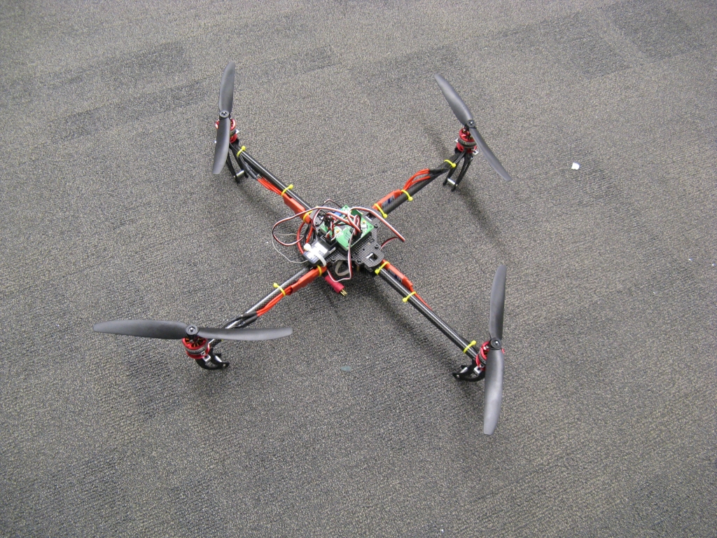
But for now, back to multirotors. The main purpose for the other six FFv1.1 boards is to test fly on the Cinestar 6 hexrotor. Before I feel comfortable enough to do that, though, I decided I should flight test the controllers on my Turnigy Talon quadrotor. It's a much more manageable size (500mm from center-to-center), but it can carry a substantial payload so it wouldn't mind the extra weight of large controllers and heavy-gauge wiring.


I was going to heat shrink the controllers, but decided to leave them bare for testing until I'm confident they don't have any bad solder joints. So, I just zip-tied them to the frame for now:


To accommodate the output signal from the KK multirotor control board, I wrote a simple PWM input routine using a spare timer on the STM32. It measures pulse length and adjusts voltage magnitude directly (no current control.) However, the voltage phase is still feedback-controlled to keep d-axis current at zero. This is a unique control scheme not possible with normal Field-Oriented Control. It should retain the "feel" of an airplane-style RC ESC but have optimal torque per amp at all speeds.

For the PWM input, I used a digital low-pass filter to limit the spin-up rate of the motors. I initially did this in lieu of current control to limit the maximum amount of current the motors would see under normal operation. However, after flying with a relatively fast input filter (τ = 33ms), I encountered the other reason why one might want to filter the input: vibration noise.


The PWM input under hover conditions would actually fluctuate by about +/-50μs (+/-8% of full range). This noise is almost certainly from the gyros on the KK board, and I don't blame the cheap controller because I had major gyro noise issues with the Pololu minIMU-9 too on 4pcb. Gyro noise due to mechanical vibration has been by far the most hassling part of building multirotors for me. In any case, it was actually beneficial to increase the input filter time constant to about 50ms and turn down the control gains slightly to reduce how much the ESCs would amplify the gyro noise.

Lastly, video of both ground and air testing:


So far the controllers are working as planned. This marks the first time I've ever tested eight controllers in one day without blowing anything up.

Sunday, May 13, 2012

2.007 = Wide-open spaces for tinyKart and Kramnikopter!

Oh yeah, there's also the whole robot contest thing:

It's like mini-FIRST.
For the past four years, I've been a teaching assistant for 2.007: Design and Manufacturing I, a sophomore-year mechanical engineering design class where students each create a small (16"x16"x12") robot to compete in an annual competition. This class, formerly numbered 2.70, is the origin of the FIRST Robotics high school level competition. If you don't believe me, here's Woodie Flowers with a giant camera octopus:


Just like in FIRST, there's a new challenge every year, and this year's game was Tech County Fair. Robots scored points for collecting arcade tickets, filling a balloon, hitting a high-striker, and spinning a scale Ferris wheel. During the competition, my main job is running the scoring computers. Here's a view from my desk down on field level:


This year, only about 76 robots (out of a class of ~140) entered the final contest, which is optional and doesn't count toward their grade. On one hand, I would like to have seen more of the robots finished. But, having fewer robots in the event means that the ones that do compete tend to be very good and the matches are more exciting. Here's a picture of the winning robot pair:


The bot with hammers on top of it would hit the high-striker (not with the hammers, those were just ballast). The smaller crab-looking bot would pinch the Ferris wheel and spin it, as shown in the picture. Both robots could autonomously find their targets and start their tasks, a huge advantage in the final rounds.

Two other really cool entries that unfortunately did not make it to the final rounds were the Whitelaw Prize (design award) winners:


The bot on the left had several unique features that I've never seen on 2.007 robots before. Instead of striking the lever, it would lift the high-striker mass with a tape measure-like constant force spring that extends from a roll inside the robot chassis. The green Banebots wheels look cool and provide tons of traction. (Are they even kit-legal?) But the real surprise was that the wheels could be steered much the same way as Twitch, having a 0º, 45º, and 90º orientation. The steering was accomplished with crossed-over belts instead of linkages. Also, the whole thing was controlled using DTFM tones from a telephone, just because.

The bot on the right has a more conventional but very well-built 2WD drivetrain. Its showpiece is a custom-made steel flywheel that spins up to a few hundred RPM. It released its stored energy into the high-striker lever so effectively that this robot damaged pretty much all of the practice levers and they all had to be replaced for the contest. It could also spin the Ferris wheel using rubber-coated rollers on the back.

You can watch the two-night competition at the following links:

At the intermission of the Finals (1:55:20 in the second video), you'll get to see the other reason why I enjoy the 2.007 final contest: three days of access to a huge venue with high ceilings. I brought 4pcb and Kramnikopter to the event and while I was testing out the $35 HD Wing Cam I just got for Kramnikopter, the AV crew asked if it could lift their GoPro. It turns out that the Talon frame is pretty much a perfect match for the GoPro, and I got to do some flyover videos of the contest field. Here's some comparison video between the cheap but lower-quality HD Wing Cam and the GoPro:


The HD Wing Cam shoots in 720p and really needs good lighting to work well. But it's small and cheap. The GoPro shoots full 1080p and has much better color balance and image stabilization, but it's $300. It really seems like the way to go for this size quad. They didn't let me keep it, though, so a few days later I went out with my HD Wing Cam and did some more outdoor testing:

You can catch a few glimpses of the giant hexrotor, which flew for a bit too!

Another new 2.007 event this year was an official Electric Vehicle Section final contest. We've had an EV Section (optional, for people who are bored with robots and like EVs) for a few years now, but there hasn't been a separate final event specifically for the vehicles. This year we ran a 50-meter drag race and a unique urban hill climb in a parking garage. (Both time trials, no actual racing for safety reasons.) You can see a full summary of the event on Charles' site. I'll just include the video highlights:


tinyKart, Chibikart, and Pneu Scooter also did some timed runs, since the instructors should be allowed to have some fun also. tinyKart did a 6.52s run on the 50m drag race, about what I would have predicted. It also did a 53.9s run up the garage with a peak power draw of 4.1kW from the batteries. I intend to finally convert tinyKart to running my DirectDrive controllers, so it's possible it will get a performance upgrade soon. (Or there will be a lot of DirectFET smoke.)

Coming soon: FFv1.1, dynamometer, Gen. 1 sensorless write-up.

Saturday, May 5, 2012

KKv0.0 Camera Platform

After a not-so-successful attempt to mount my HD video camera to a Turnigy Talon quadrotor frame, I concluded that the camera is a bit too heavy for this configuration, and that better vibration isolation material would be needed. A GoPro is much more well-suited to the task, so maybe that will happen in a future version. But I also ordered one of these $37 720p minicams, which have gotten mixed reviews. It's much lighter than either of the alternatives and I would be much less sad if I lost it in a crash.

For now, though, I decided to explore vibration isolation options without solving the problem of having a too-heavy camera on this motor/prop combo. The two materials I tried in v-1.0, felt and closed-cell foam tape, both failed to damp whatever frequency of mechanical vibration was causing the camera to be shaky. So, I went for a known solution of memory foam (e.g. McMaster PN 86195K314).


There's a 1/4-20 screw going into the bottom of the camera that, with a large washer, sandwiches the camera mount in between two pieces of memory foam. Here's what it looks like on the frame:


The improvement in video clarity was impressive, though it didn't eliminate the vibration completely. The camera is still too heavy, so the whole thing is hard to fly and the motors and ESCs get hot. But here's the result:

Thursday, May 3, 2012

Cambridge Mini Maker Faire + Kramnikopter

A couple weeks ago I went to the Cambridge Mini Maker Faire. It's a smaller event than the full-scale NY Maker Faire I went to in September, but it's much closer to home. In fact, it's within walking distance, so I decided to kart everything over.

Yes, kart.
It turns out that tinyKart makes a pretty good hand truck. Also along for the ride was Pneu Scooter (ziptied to the frame), Twitch, and 4pcb (in the seat). Unfortunately, the Mini Maker Faire is too crowded for the vehicles to be effectively (or safely) demo'ed. And it was too windy to fly 4pcb.


So that just left one option:

Balloon Twitch.
You can see how windy it was by how far the balloon is deflected. The balloon was my way of making sure that nobody stepped on Twitch accidentally, but it also made the robot a lot more "interactive". And by that I mean that several little kids were teased.


Sorry for the blue video...forgot to turn off manual white balance...

You can find more photos from CMMF 2012 in the Flickr pool.

I was really looking forward to demo'ing 4pcb, since it drew so much attention at the NY Maker Faire despite not actually being flyable at that point. It's small enough not to pose much of a safety risk, but micro quads really don't like wind. In general they're twitchy and hard to fly. Giant hexrotors have the opposite problem: they're very stable, but too dangerous to use anywhere near people.

To fill the gap in my flying things fleet, I decided to put together a Turnigy Talon frame from Hobby King. I got to fly one that was put together by Daniel Kramnik (of Tesla Coil fame) and was very impressed with the quality of the frame. For $34, you get a real carbon fiber + aluminum frame. Add to that four $7 motors, four $14 ESCs, and $18 battery, a $3 bag of props, and $15 control board, and you get a complete mid-size quadrotor kit (bring your own radio) for $154.

Kramnikopter!

Here it is with 4pcb propped on it for size comparison:


The Talon frame is very impressive, even without considering the cost:performance ratio. It's stiff and light and it looks amazing. It also seems very durable - you'd have to crash pretty hard to break it and the landing gear is nice. When you take into account the fact that it's $34, it is one of the best deals I've seen.

The motors, on the other hand, leave something to be desired. They are the most inexpensive of an already low-cost/low-quality brand name, which means they have some issues. Mostly, I ran into axial alignment problems - the can and shaft are poorly constrained. They are also not balanced. If I were to replace one component right now, it would be the motors. They do look cool, though. 

For what it is, the KK board is an impressive deal as well. It's rate-mode only, so it can't do self-leveling, position hold, altitude hold, or any other more advanced features. 4pcb flies in self-leveling attitude mode, so returning the sticks to center means it tries to go to level (zero angle). So it took some practice for me to learn how to fly Kramnikopter in rate mode, where returning the stick to zero means zero angular velocity. You can see me learning the new input mode a little at the start of this video:


After filming the first half of that video with it, I decided to go ahead and attempt to fly my HD video camera. I have a long history of attaching my camera to things that move, but this would mark the first time that it's actually left the ground. The mount I made was pretty simple:

Kramnikam v-1.0
On one hand, the camera flew and survived. But it's not quite a cinematic experience yet. This camera weights exactly 300g, and it's just a little bit too heavy for this combination of motors and props. The resulting flight is very close to being unstable, since the motors are almost maxed out. The more obvious problem is that my initial vibration isolation solutions (foam tape, felt) didn't help much. So, lighter camera and softer mount seem to be the next steps. For now, I have a really nice medium-sized quad to play with.

Thursday, April 19, 2012

Sensorless Start-Up / Speed Control

It's spring demo season again. I'll be at the Cambridge Mini Maker Faire on Friday, along with the MITERS crew, with an assortment of projects. Come check it out. Follow-up post to come.

For now, time for a massive multi-controller update. The Sensorless, Sine-Commutated Field-Oriented Current Control (SSCFOCC) algorithm I've been working on has been sufficient abstracted now that I can develop for it on two different motor controllers (3ph v3.1 and FFv1.0) at the same time. (3ph v4.0 is coming soon and DirectDrive v1.0 still exists, I promise...)

Before I start developing new hardware and potentially writing a entirely different sensorless control algorithm, though, there were some loose ends I wanted to clean up in the current algorithm. Once these points are addressed, I will go back and write up a summary of my first-generation sensorless code since by now it's too complex for individual blog posts.

But First...


More Position Filtering

Loose End #1 was a problem with the rotor position estimating filter used to clean up the rotor angle at high speeds. I added this at the end of the last sensorless post and even though it immediately improved the high-speed performance of FFv1.0 on the hexrotor motors, there was a weird side-effect on the flux vs. angle graph. The flux estimate would begin to lead the rotor angle estimate at high speeds, which should not happen since the rotor angle estimate is derived from the flux estimate. The flux vs. angle curve should be constant. What the?

After staring at the code for a little while, I identified this a rather complex software error on my part tracing all the way back to a subtlety of BWD's sensored FOC code... I'll spare you the details, but I fixed it and now the flux estimate is much nicer:

Pneu Scooter w/ 3ph v3.1. Compare to unfiltered flux estimate.
Much of the "noise" from the 2d plot is shown to be offset at low speed (<200rpm).
Hexrotor motor with FFv1.0. Compare to the unfiltered flux estimate.
And in nauseating pseudo-3d.
The low-speed offset is a known issue having to do with the fact that the integrator at the heart of the flux estimate is implemented as a low-pass filter. There is also a phase offset in the flux estimate resulting from this practical non-ideality:


Since this is a known offset, it could potentially be subtracted off. Or the low-pass filter could be designed such that at the start-up routine exit speed, the offset is less than 15º or so. For the data above, that would be about 150rpm. Speaking of start-up routines...

Start-Up

Loose End #2 was the lack of any start-up routine for either controller. I've been putting it off for a number of reasons. For one, Pneu Scooter really doesn't need a start-up routine. The sensorless algorithm has no trouble picking up the rotor speed at as low as 50rpm and that's well within single-kick speeds:

One kick gets to 75rpm, at which point the flux estimator has locked in.
Also, Pneu Scooter really doesn't have enough torque to justify a no-kick start-up routine. Even at peak current (40A), the acceleration is something like 150rpm/s. The sensorless start-up will achieve far less than peak torque, though, since it won't have the benefit of optimum current vector placement. So it could mean a couple seconds of balancing on a barely-moving scooter while the speed ramps up. It's just much more natural to kick start.

FFv1.0 and the hexrotor motors, on the other hand, almost definitely need a start-up routine. Even though in this video, a very large (14x4.7SF) prop starts cleanly and quickly with no start-up routine at all. The command PWM goes high enough that the motor is forced to do something, and by luck it gets kicked in the correct direction at sufficient speed for the flux estimator to lock in. But this is unreliable (works maybe 50% of the time) and inelegant, so it should really have a slow-ramping startup routine as well.

Maybe the real reason I haven't implemented a start-up routine yet is because it's easy. At least, the most obvious way of doing it is easy. Lacking position information, there isn't much choice in how to drive a brushless motor: it becomes a coarse stepper. Except with sinusoidal commutation it can be like a microstepping coarse stepper, which is still pretty smooth. The point is, the only way to drive it with no knowledge of the rotor position is to put current in somewhere and wait long enough to know that the rotor has most likely reached the position you told it to go to. With that in mind, I wrote a simple start-up routine with four states:
  1. IDLE: Wait at zero speed until the user commands a positive torque or speed.

  2. PARK: Place current vector at a fixed angle and wait for some time for the rotor to reach a stable position.

  3. RAMP: Rotate the current vector with a constant angular acceleration that is sure to be achievable by the rotor given the amount of current commanded and the estimated load inertia.

  4. RUN: After a certain speed, switch to sensorless field-oriented control using the rotor angle predicted by the flux observer.
The ramp state here differs a little from BLDC-style sensorless start-up routines that use six-step voltage-mode commutation. Since this ramp state is still current controlled, the possibility for variable user-commanded acceleration during "open-loop" start-up is present. The angular acceleration of the ramp is linked to the amount of current commanded. If you go light on the throttle, the ramp takes longer.

Since the load inertia can't be exactly known, the start-up ramp acceleration has to be conservatively chosen. The start-up torque will therefore be significantly less than the run torque, and the efficiency will be very low. This is a common trait of sensorless start-up algorithms and the best way to minimize the effect is probably to get out of start-up as soon as possible. Transitioning to closed-loop sensorless control at 5-10% of the maximum speed seems to be achievable.

Anyway, enough hypothesizing. Here is my first shot at a sensorless start-up for Pneu Scooter, the harder of the two challenges:


The ramp goes from 0 to 150rpm in about 3 seconds with 30A commanded current. This is about 50% of the acceleration that would be expected from closed-loop control, so it feels sluggish for the first three seconds. But, it is smooth and transitions cleanly to run-state closed-loop control at 150rpm. Making the ramp faster results in pole slipping, so this is about as good as it will get.

One option for improving the start-up is to get out of the ramp state earlier. The flux estimator is able to pick up the rotor movement at as low as about 25-50rpm, so waiting around until 150rpm sounds silly. But, the low-pass filter-induced phase lead is still very high at those speeds, so the transition doesn't work reliably. It's clear that the low-pass filter time constant and the ramp exit speed are coupled in this way. Something to think about for future optimization.

Another option is to use more current. This doesn't help the efficiency, but it will create a faster ramp. 60A for a short period of time shouldn't hurt the motor or controller, but I'll wait for 3ph 4.0 to test that.

Start-up for the hexrotor motors is a much simpler problem. For one, they have essentially no load at start-up when the prop is moving too slowly to create significant thrust or drag. The performance of the controller is also not at all dependent on low-speed torque characteristics since the minimum RPM seen in flight will be well above the run-state threshold. Here's a very light ramp (<5A) for the 14x4.7SF prop:


The threshold for transitioning from ramp state to run state is 600rpm, and once it transitions to run state the torque increases dramatically. The ramp can afford to be much faster without slipping poles, but for the purpose of reaching a safe idle speed for the prop, it almost doesn't matter. Note that the speed goes directly to idle speed, 1,000rpm, and sits there. That brings me to...

Speed Control

Loose End #3 is speed control for FFv1.0. Pneu Scooter, as a vehicle, is happy with current (torque) control. But for the hexrotor, the master controller may want to command an exact speed for each rotor. Speed is directly related to static thrust (though not linearly). Steady-state current is also related to static thrust (close to linearly). But with inertial transients to deal with, the performance of a speed-based controller might be better.

Actually, the simple way to do "speed" control is to directly vary the PWM duty cycle, bypassing the current control entirely. This controls speed because motor speed is approximately proportional to applied voltage, which is controlled by the PWM duty cycle. As it turns out, it's definitely possible with the modified Synchronous Current Regulator (mSCR) to use this control mode, bypassing the q-axis current controller but leaving the d-axis (phase) controller working. This gives the benefits of FOC (dynamically adjusted motor timing) but the simplicity of direct PWM control. In fact, this was what I used for the first few tests of FFv1.0. Here's some data showing it executing step "speed" commands:


At each step, the q-axis and d-axis current spike due to the inertia of the motor and prop. But, the back EMF brings the q-axis current back to a steady-state value as the prop speeds up or slows down, and the mSCR adds or subtracts from the phase to bring the d-axis current back to zero.

The benefits of direct PWM magnitude control are simplicity and robustness. With current limiting to prevent the spikes from damaging components, I think this could be a pretty good way to run a multirotor controller. It's how most ESCs operate, so it would feel normal. But, it has several downsides:

  1. It can't achieve minimum rise time. The step in voltage magnitude will give only as much current as the motor resistance will allow. A smarter controller could slew the motor faster using a voltage that is higher than the steady-state value at the target speed.

  2. It can't accommodate minor difference in motors/ESCs/props. If one motor is slightly weaker than the others, it will spin slower under PWM magnitude control. The master attitude controller's integral term can correct for this, but why rely on this?

  3. Motor speed is only roughly proportional to applied voltage. The actual speed depends on the back EMF, which is V-IR. At higher loads, the speed per applied volt is lower. Does this matter? Maybe not, since none of this is linearly proportional to thrust anyway.
A classical approach to true speed control would be to wrap an outer PID control loop around everything:


The speed control loop, a generic PID with saturation, feeds the q-axis current reference a value between the maximum braking current and the maximum accelerating current, depending on the speed error. The d-axis controller is still simply trying to maximized torque per amp by adjusting motor phase. (The more I think about it, the more the mSCR strategy makes sense in this regard.)

This video shows the start-up and PID-based speed control for FFv1.0 with the 14x4.7SF props:


The nice thing about PID control is that it's easy to understand and easy to tune. Unfortunately, the load in this case is very nonlinear. As the speed increases, the damping due to propeller drag goes up. So, the step response changes depending on the speed:

Real data from the 14x4.7SF prop.
From 1,000-2,000rpm, the chosen gains exhibit a lot of overshoot. From 4,000-5,000rpm, they're overdamped. With this data as a starting point, I made a quick simulation including the nonlinear prop load. Another nice thing about PID is that it's very easy to work with in a Simulink:

This is what grad students do all day.
After some shady parameter estimation, I could almost predict the step response shapes:


The real-life response is actually a bit faster than the simulated response, for some reason. Not going to complain about that. But, they're both pretty slow overall. The motors never reach peak current during speed steps. The slew rate can and should be much faster for the best possible speed command tracking. By tweaking the gains in Simulink, I can now get a feel for which way they should be pushed in real life to speed up the response and kill off some overshoot.

I also think there's a better way. This post is already quite long so I'll have to save that for next time, but there is a hint of it in the Simulink diagram...

For now, I leave you with a Kramnikopter that I bought for basically nothing and will be doing absolutely zero custom development for:

Yay, not-complicated flying things.

Friday, April 13, 2012

4pcb: 3S/370mAh Testing

Previously, I promised some PCB quadrotor testing on a 3S/370mAh battery instead of its former 2S/460mAh. They're both Turnigy nano-tech packs with a 25-40C discharge rating, so I am only trading mAh capacity for more voltage. In actuality, the 3S does store more energy (1110SmAh vs. 920SmAh to use a nonexistent unit of energy). Accordingly, it's also physically larger:

3S/370mAh (left) vs. 2S/460mAh (right)
And, it weighs more. The 2S/460mAh weighs 30.0g, while the 3S/370mAh is 36.6g. (In both cases, this comes out to about 113Wh/kg, which seems reasonable for a small power-cell pack where much more of the weight is packaging and connector.) Generally, adding 6.6g of weight to a micro quad is going to hurt a little, but if you're going to add weight somewhere, the battery is a good place to do so.

Theorem 1: "LiPoCopter Theorem" As the ratio of battery weight to total weight (LiPoCopter ratio) of an RC helicopter/multirotor increases, it is increasingly likely to be able to fly with properly chosen motors, props, and ESCs.

Proof: Consider the extreme case: a helicopter made out of a LiPo (possibly one of these, with two rotors attached to it like a LiPo-bodied Chinook). It is certainly possible to choose a set of components {motor, prop, ESC} which will allow this to fly. As any helicopter/multirotor approaches this ratio of battery to total weight, there will be some set of components which allow it to fly.

A respectable LiPoCopter Ratio of 26.4% (formerly 22.8%).
Of course, I don't get to choose an arbitrary set of components for 4pcb; I'm stuck with the existing motors, props, and controllers. I had a hunch that it would fly better, though, since the ESCs would very much like to see more voltage. They're rated for 7-42V, so running on 2S (7.4V) is very borderline. 3S (11.1V) gives much more margin for voltage sag under load. The weakest motor would tend to reach command saturation well before the 2S battery was dead, leading to drifting and ultimately instability.

The improvement on 3S was immediately apparent, with no additional work required. Here's a comparison of the motor commands for full-length flights on 2S and 3S:

2S/460mAh
3S/370mAh
In the 2S/460mAh flight, the average command to hover starts at about 200 (out of 255) and increases as the battery voltage drops, up to about 220. The problem is the front motor: after some time, it begins to saturate and when it does, it can't produce any extra thrust to counteract for disturbances. In flight, this causes the quad to pitch forward, especially on throttle-up, and makes it difficult to fly. You can see I had to land several times to let it re-stabilize. The total flight time was about 6 minutes, but the last 2-3 minutes were me fighting to keep it in the air. Usable flight time was about 3-4 minutes and even at the end of the flight, the battery was still above 7.4V (only 50% discharged).

The 3S flight is one continuous stretch of over 8 minutes in the air. The average command to hover starts at about 165 and increases to about 185 as the battery voltage drops. This leaves plenty of margin for stability, so even though the front motor command is still highest, it never saturates. The problem of uncontrollable pitch as the battery gets discharged is eliminated. One side-effect of having higher voltage is that all the gains are now too high, causing small/fast oscillations (compare the width of the lines in the above images). This should be easy to fix. After 8 minutes, all four motors start to taper off in power. And all of the battery capacity was used:

3S/370mAh after 8 minute flight. Total voltage: 9.02V.
Luckily, I bought four of the 3S/370mAh packs, so I now have enough capacity for 32 minutes of continuous flying. Just in time for demo season.


Sunday, April 1, 2012

TI Workshop + The Joys? of High-Speed Motor Control

I spent the past week at the Texas Instruments C2000 MCU Real-Time Industrial Control Training in Waltham, MA. It was really good workshop that I would highly recommend for anyone who wants to get into real time motor control. The next events are in Michigan and Wisconsin in May and June. The three-day event covers control theory on day 1, motor control specifics on day 2, and a C28x microcontroller intro on day 3, for which you get an F28069 Piccolo controlSTICK to keep:


In the interest of fair reporting, I will say the that feature set of the TMS320F28069 microcontroller does give it a few advantages over the STM32F103C4 that I currently use. It's a 32-bit processor (not ARM based) and can run at up to 80MHz. But, it has a built-in FPU and control-law accelerator, something not found until the F4 line of the STM32s. It also has more PWMs (16) and ADCs (16) than the smaller STM32F1s. As far as the available IDEs, I've used both IAR EW and Code Composer Studio before and I find them to be equally annoying. And I hate JTAG/emulated debugging anyway. 

I don't see myself switching away from the STM32, but I've had good experiences with the TI MSP430 line and I wouldn't hesitate to recommend those or the more powerful C2000's for people looking to escape from Arduinoland.

Since I'm always talking about how convenient it is to have a compact electric scooter that folds so you can take it on public transportation, I decided to try it out on my way out to Waltham. The bus from near me stops just on the other side of Prospect Hill Park from the TI offices:

No problem. This should be a nice traffic-free scooter ride through the pa-  
Oh.
I guess I neglected to consider the fact that Prospect Hill Park might actually be named for its predominant topographical feature. Pneu scooter is good at a lot of things, but hills are not one of them.

So I guess I'll be hiking.
Also, some of the paths are just dirt trails. The good news is that that's the TI parking lot right there.
Well at least I could have a fast trip down the hill on the way home - Oh no wait, it tore my brakes apart on the first two days. By the third day, with repaired brakes, I had pretty well optimized energy usage so that I could minimize hiking up the hill and coast the entire way down. Still better than driving in Boston rush-hour traffic.

Anyway, although all three days of workshop were great, I was especially interested in Dave (Wisconsin) Wilson's Motor Control Seminar. Most of the slides are available on his blog if you are interested. I learned a bit more about TI's InstaSPIN BLDC control scheme, and am beginning to sort out the various types of sensorless control methods.


One thing I picked up which I have to think more about is that what I have previously referred to as an open-loop flux estimator is in fact not as far different from a closed-loop observer as I had thought. The difference is more subtle and possibly less fundamental than it seems. For example, here is a closed-loop single-phase back EMF/current observer with a PI compensator:


With just one page of math, I can unwrap the feedback loop and rewrite it in the form of my "open loop" flux estimator, plus an additional low-pass filter. The closed-loop form still has the advantage of keeping an internal state for current estimate, which is probably way cleaner than the measured current. But they're not fundamentally different as I had once thought. Go figure... 

Maybe the important distinction then isn't between open-loop and closed-loop formulation for the observer. Maybe the fundamental difference is between observers that work only on electrical quantities and ones that include a mechanical state (speed, position). The addition of a mechanical state would almost certainly improve the performance of either observer, since it would anticipate the trajectory of I and E as the motor rotates. No wonder this is the type of observer described in the Book of Mevey, which has been right about everything else so far.

Back to reality.

My immediate task is to get this thing spinning:


After realizing that I wouldn't be able to hear anyone coming over the noise of the propeller, I added this:


In the previous post, I had gotten FFv1.0 up and running using Pneu Scooter as a test motor. The TI DRV8301 gate driver/everything chip performs well. But, the first time I attempted to run the motors on the hexrotor, I ran up against some not entirely unexpected issues with high speed control. At full speed, the electrical frequency of these motors can be 1,000Hz or higher. Every part of the control loop from the currrent sensors to the digital filters has to keep up with this, and in fact exceed it by a large margin to minimize phase lag. This is a tall order with a 15.625kHz PWM-limited control loop.

What I found on the first attempt is that at high speeds, the flux estimate becomes noisy and its zero-crossings, which are used to mimic Hall effect sensor transitions in my sensorless method, become blurry and unreliable. As a result, the position estimate would become noisy, which would lead to incorrect voltage vector placement. This leads to even more noisy current which leads to an even more noisy flux estimate, and so on. The physical result would be a motor that sounded very unhappy and current measurements that are all over the place starting at just under 5,000rpm. Under load, it could lose sync and crash entirely, surviving only because it was running on a current-limited power supply.

As an attempt to remedy the problem, I'm trying an idea I first thought of a long time ago for use with Hall effect sensor-based field-oriented control. The algorithm already uses a time-based interpolator to work between one flux zero crossing (or Hall effect transition) and the next. Instead of trusting the new zero crossing's position estimate 100% of the time, it's possible to use an IIR-style filter to merge the interpolator with the new position. Maybe this will help:

Maybe.
When the new flux zero crossing or Hall effect sensor transition comes in, it generate an angle (blue) which previously would be taken as the true angle. Now, that blue angle is averaged with the current estimate based on time interpolation (brown) to create the new estimate (purple). The relative degree of weighting for the average is set by a parameter, A, just like and IIR filter.

At high speed, when the blue vector is popping up at the wrong time due to noise, this filter will help stabilize the rotor angle estimate. And what a difference it made, without any tuning whatsoever. Here's some video of spinning up the larger prop, a 14x4.7SF:


One interesting thing is that I haven't even written a startup routine yet, but most of the times it starts just fine. I guess I'm used to vehicle controllers where if you don't write a startup routine they just sit there and buzz angrily. Also interesting is that once it does start, it can run at as low as 370rpm, which is about 7.5% of the top speed. So that would be my target speed for exiting the startup routine and entering run mode.

I can tell from the data that the angle filter helped a lot - the current is much cleaner. Here's a plot of the flux and phase currents with respect to the estimated angle:


Things are mostly in the right place and the flux estimate has the correct magnitude. (The flux is related to the motor constant or the rpm/V constant.) Something fishy is going on with the phase of the flux estimate. Its peak should stay right on 180º, since that's being used to define the d-axis. But instead it starts to shift forward at high speeds. As it turns out, I messed up the filter code a bit, so I'll have to go back and fix this one later.

For now, I also did some benchmarking against a Turnigy Sentilon 100A HV, a very good brushless motor controller. I measured (using a clamp multimeter) the AC RMS phase current and the DC bus current at different speeds running with the Sentilon 100A HV and with FFv1.0:


The not-very-interesting result is that they pretty much overlap so far. So I am at least not doing worse then good-but-dumb brushless DC controllers. It's definitely possible that any advantage of FOC will be lost in these motors because they are so efficient in BLDC mode already. Typically, high-speed low-inductance motors can operate very well with square wave drive. 

But there are other advantages that I'm still counting on. One which I was reminded of accidentally is that this controller can do four-quadrant drive. It can, in fact, brake so hard that it can unscrew the prop adapter and send a propeller flying across the room. Having braking should improve the response time of the motors to negative speed steps, which can help the control be snappier.

I've only just barely scratched the surface of the number of parameters that can be tuned. My next task will be to explore the effects of changes to the various motor parameter estimates, the filters, and the limits. Then, to see how it responds to more dynamic inputs. Then collapse everything into a simple enough interface that it could be used by other people. But so far, it's been a relatively problem-free controller build for once...